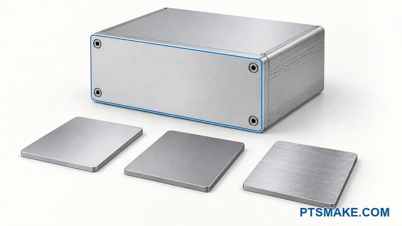

Are your AI server racks running hotter than your cooling system can handle? Air cooling has hit its ceiling, and TIM gaps from poor surface flatness are quietly costing you 10-15% in thermal performance.
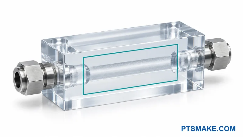
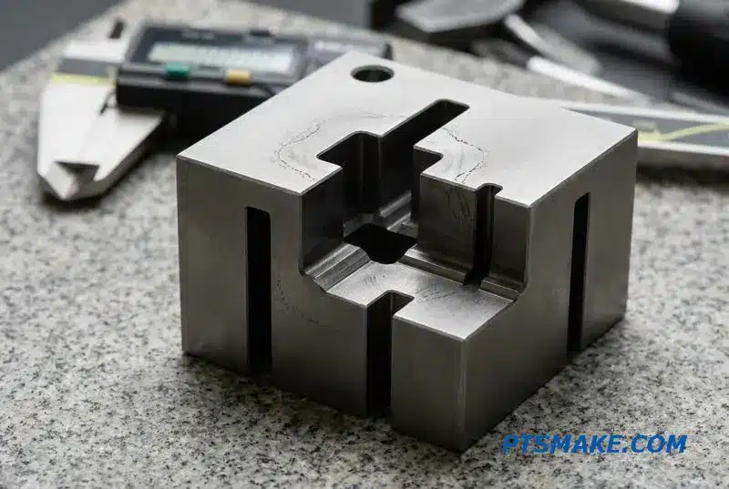
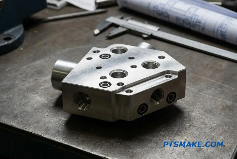
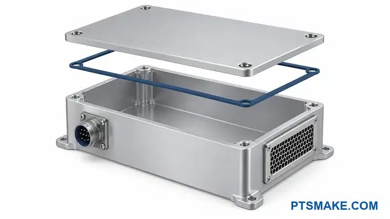
Custom CNC machined liquid cooling cold plates are precision-milled copper or aluminum heat exchangers with internal flow channels, designed for direct-to-chip cooling in AI data centers, HPC systems, and high-power electronics requiring sub-0.01mm flatness and complex channel geometries.
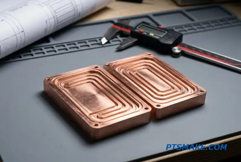
In this guide, I’ll walk you through everything I’ve learned about cold plate manufacturing at PTSMAKE—from material choice and channel design to brazing, flatness control, and real production case studies. Let’s get into it.
Why AI Data Centers Are Hitting a Thermal Wall — and Cold Plates Are the Escape Route
The era of air cooling for high-density computing is ending. With AI workloads pushing rack densities past 80kW, traditional methods are failing. This isn’t just a future problem; it’s happening now. The data center thermal wall for AI cooling is a significant barrier to performance.
The Inevitable Shift
We’re seeing a clear trend. A recent S&P Global report indicates that 21% of data center operators are planning a transition to liquid cooling within this year. This highlights the urgency and the industry’s response to the direct-to-chip cold plate adoption trend.
Market Momentum
The market for liquid cooling solutions reflects this urgency. Projections show significant growth, driven by the demand for more efficient thermal management in AI and HPC environments.
| Market Metric | Projected Value |
|---|---|
| 2025 Market Size | $4.68 Billion |
| CAGR | 18.6% |
This growth underscores that liquid cooling, particularly using cold plates, is becoming the new standard.
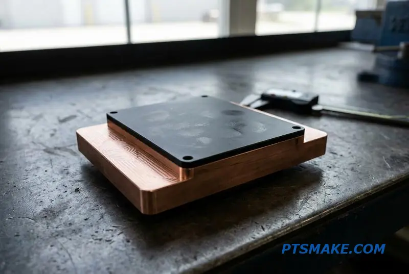
The core issue isn’t just about removing more heat; it’s about removing it directly from the source. Traditional air cooling struggles with the concentrated heat generated by modern GPUs and processors. It’s an issue of thermal density, not just total thermal load. This is where direct-to-chip solutions excel.
Why Direct-to-Chip is Essential
Liquid cooling cold plates offer a direct path for heat to escape. By attaching a liquid-filled plate to the processor, heat is transferred far more efficiently than through air. This allows chips to run at their optimal performance levels without throttling due to excessive temperatures.
However, implementation requires precision. The interface between the chip and the cold plate is critical. A poor connection, misaligned components, or materials with mismatched Coefficient of Thermal Expansion1 can compromise the entire system. Our work with clients shows that manufacturing tolerances for these plates are extremely tight.
Air vs. Liquid Cooling Effectiveness
This table illustrates the fundamental difference in heat transfer capabilities, based on our internal testing.
| Cooling Method | Heat Transfer Efficiency | Power Density Suitability |
|---|---|---|
| Air Cooling | Low | Below 30kW/rack |
| Liquid Cooling | High | Above 80kW/rack |
The transition to liquid cooling isn’t just an upgrade; it’s a necessary evolution to unlock the full potential of AI infrastructure.
As AI demands push rack densities higher, air cooling is no longer viable. Direct-to-chip liquid cooling, led by precisely engineered cold plates, provides the necessary thermal management, making it an essential technology for the future of high-performance computing data centers.
Copper vs. Aluminum Cold Plates — Thermal conductivity Is Only Half the Story
When choosing a material for liquid cooling cold plates, everyone points to copper’s superior thermal conductivity. While true, focusing only on that number can lead to an over-engineered and costly solution. The best choice balances thermal performance, weight, and manufacturing cost for your specific application.
Material Properties at a Glance
Aluminum is often a practical starting point due to its lower cost and weight. Copper is the premium choice for extreme heat loads where performance is the only priority. The decision isn’t always straightforward.
| Property | Copper (C110) | Aluminum (6061) |
|---|---|---|
| Thermal Conductivity | ~400 W/mK | ~200 W/mK |
| Density | 8.9 g/cm³ | 2.7 g/cm³ |
| Relative Cost | High | Low |
| Machinability | Fair | Excellent |
When to Choose Each Material
For most commercial electronics and industrial systems, aluminum offers sufficient cooling at a much lower price point. However, for applications like high-power data center GPUs or specialized medical lasers, the superior copper cold plate thermal performance is non-negotiable.
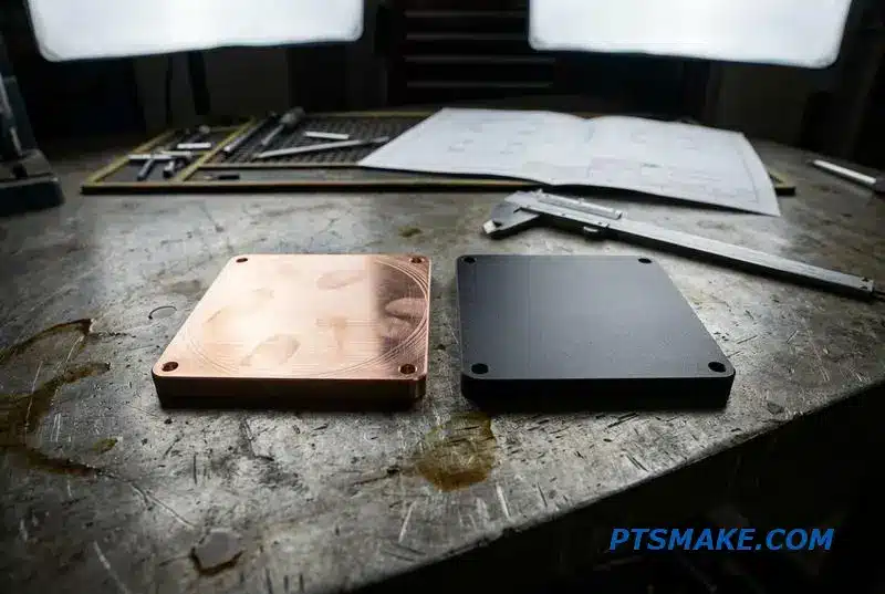
The debate of aluminum vs copper liquid cooling extends beyond raw numbers. At PTSMAKE, we often guide clients through a more nuanced cold plate material selection guide. Machinability, for instance, directly impacts final cost. Aluminum is easier to machine, allowing for more complex internal fin structures without a dramatic price increase.
Beyond a Single Material: Hybrid Designs
We’ve found that hybrid designs often provide the best of both worlds. A copper base can be embedded or brazed into an aluminum body. This approach targets the high Heat Flux2 area directly under the heat source with copper while keeping the overall structure light and cost-effective.
This strategy is particularly effective for large-format liquid cooling cold plates where a full copper build would be prohibitively heavy and expensive. It allows for targeted performance without overspending.
Application-Based Recommendations
Here’s a simple breakdown based on projects we’ve handled. This table helps clarify which material typically fits certain thermal demands.
| Application | Recommended Material | Rationale |
|---|---|---|
| Consumer Electronics | Aluminum | Cost and weight are primary drivers. |
| Industrial Power Inverters | Aluminum | Good balance of performance and cost. |
| High-End PC Gaming | Copper or Hybrid | Maximum performance is desired. |
| AI/HPC GPUs (>700W) | Copper | Highest thermal conductivity is required. |
Ultimately, selecting the right material for liquid cooling cold plates requires balancing thermal load, budget, and weight. Copper offers peak performance, but aluminum is often the smarter, more cost-effective choice for a wide range of applications. Hybrid designs provide an excellent compromise.
Microchannels, Pin Fins, and Serpentine Paths — Cold Plate Flow Channel Design Explained
Choosing the right internal flow channel for liquid cooling cold plates is critical. This decision directly balances thermal performance against hydraulic demands. Each design offers unique advantages, and understanding them helps in creating an efficient cooling solution for specific applications.
Key Design Tradeoffs
The primary challenge is managing the thermal-hydraulic tradeoff. Increased surface area or fluid turbulence improves heat transfer but also raises the pressure drop. This requires more powerful and costly pumps to maintain flow, impacting overall system efficiency.
Common Flow Geometries
Different applications call for different strategies. A high, uniform heat load benefits from one design, while concentrated hotspots require another. Here’s a quick comparison of the most common internal geometries I work with.
| Channel Type | Primary Advantage | Ideal Application |
|---|---|---|
| Microchannels | High surface area | Uniform, high heat flux |
| Pin Fins | Induces turbulence | Targeting hotspots |
| Serpentine Paths | Long fluid dwell time | Overall temperature uniformity |
| Drilled Channels | Simple manufacturing | Low-performance needs |
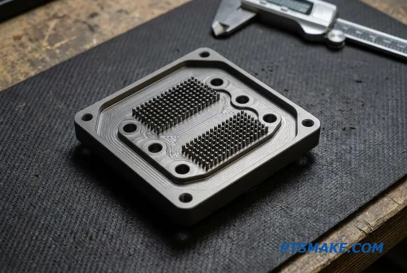
Diving deeper into each geometry reveals its specific strengths and weaknesses. The goal is always to maximize heat removal while minimizing the required pump power. It’s a delicate balance that defines effective cold plate engineering.
Straight Microchannels
For high, evenly distributed heat loads, a microchannel cold plate design is often my recommendation. These parallel channels create a massive surface area for heat exchange. However, this dense configuration leads to a significant pressure drop, which must be factored into the system design.
Pin Fin Arrays
When dealing with localized hotspots, like under a specific processor, pin fin cold plate geometry is superior. The pins disrupt the coolant flow, creating turbulence that breaks up the thermal Nusselt number3 and boosts local heat transfer exactly where it’s needed most.
Serpentine and Drilled Channels
Serpentine channels force the coolant along a winding path, increasing its contact time for better temperature uniformity across the plate. Drilled cross channels are a simpler, lower-cost option but offer limited performance and are less common in demanding applications today.
The Role of Manufacturing
Modern CNC machined flow channels enable these complex geometries with precision. At PTSMAKE, we can create intricate pin fins or microchannels that are impossible with older methods like casting. This manufacturing flexibility is key to achieving optimal cold plate pressure drop optimization.
Selecting a cold plate channel geometry involves a critical trade-off. Microchannels maximize surface area, pin fins create turbulence for hotspots, and serpentine paths improve uniformity. The optimal choice balances thermal performance against the hydraulic penalty, a feat made possible by precision CNC machining.
Hybrid Cold Plate Manufacturing — When CNC Machining Plus Brazing Beats All-CNC
When designing high-performance liquid cooling cold plates, a single block of metal isn’t always the answer. While fully CNC-machined cold plates are excellent for many applications, they have physical limitations. The hybrid approach of combining CNC machining with brazing unlocks superior thermal performance.
Overcoming Tool Limitations
The primary constraint of a monolithic (single-piece) design is the reach and diameter of the end mill. Deep, narrow, or complex internal channels are often impossible to machine from a solid block. This is where a two-piece, hybrid design excels.
A Tale of Two Methods
The hybrid method creates complex internal geometries by machining two separate plates and then joining them. This allows for features that would otherwise be impossible, optimizing the flow path for heat dissipation in a vacuum brazed cold plate.
| Feature | All-CNC (Monolithic) | CNC + Brazing (Hybrid) |
|---|---|---|
| Channel Complexity | Low to Moderate | High to Very High |
| Channel Depth | Limited by Tool Reach | Virtually Unlimited |
| Wall Thickness | Thicker (Structural) | Thinner (Optimized) |
| Design Freedom | Restricted | Greatly Expanded |
This method is a core part of our manufacturing strategy at PTSMAKE, allowing us to deliver solutions tailored to specific thermal challenges.
The process for a CNC machined and brazed cold plate begins with two separate plates. We machine the intricate channel network into the base plate and then machine a flat cover plate. This pre-machining ensures a perfect, gap-free fit-up, which is critical for a successful bond.
The Joining Process
These two components are then joined using a specialized process. Vacuum brazing is the most common method, creating a strong, leak-proof seal in a controlled environment. This prevents oxidation and ensures the integrity of the final assembly, which is vital for all liquid cooling cold plates.
Advanced Alternatives
For even more demanding applications, we also utilize other joining techniques. A friction stir welding cold plate offers a solid-state weld with excellent strength. We also use Diffusion Bonding4, a process that joins materials at a molecular level under high pressure and temperature without melting.
Our investment in these advanced assembly pathways, alongside our extensive CNC capabilities, allows us to provide the optimal manufacturing solution. This cold plate manufacturing method comparison ensures we match the process to your performance, budget, and material requirements every time.
For high-performance liquid cooling cold plates, a hybrid CNC-plus-brazing approach often surpasses all-CNC methods. It unlocks complex internal geometries for superior thermal management, demonstrating that the smartest manufacturing solution combines the best of different technologies for optimal results.
Why CNC Machining Delivers Better Cold Plate Flatness Than Any Other Process
In high-performance electronics, the flatness of a liquid cooling cold plate is not just a specification; it’s a critical performance factor. An uneven mounting surface creates microscopic gaps between the cold plate and the heat source. These gaps, filled by thermal interface material (TIM), act as insulators.
The Problem with Imperfect Flatness
Even a small gap significantly increases thermal resistance, hindering heat transfer. This is why the cold plate flatness tolerance is so important. CNC machining consistently achieves superior flatness, directly improving thermal efficiency and ensuring your components stay cool under load.
Comparing Manufacturing Processes
Different methods yield vastly different results for flatness.
| Manufacturing Process | Typical Flatness Tolerance | Impact on Performance |
|---|---|---|
| CNC Machining | 0.01 mm or better | Minimal TIM gap, optimal thermal transfer |
| Casting / Skiving | 0.05 mm – 0.1 mm | Larger TIM gap, increased thermal resistance |
| Extrusion | > 0.1 mm | Significant performance loss, unsuitable for direct mount |
As you can see, CNC machining provides a clear advantage for liquid cooling cold plates.
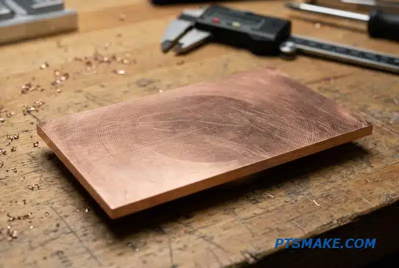
The Critical Role of TIM and Surface Finish
The core issue with a thermal interface material gap in a cold plate is its low thermal conductivity compared to metal. A flatness of 0.05mm requires a thicker TIM layer to fill the void, which traps heat. A CNC machined surface flatness of 0.01mm minimizes this gap.
Quantifying the Performance Gain
Our tests with clients show this difference isn’t trivial. Reducing the gap translates to a 10-15% improvement in thermal transfer at the interface. For high-power density chips, this can be the difference between stable operation and thermal throttling, directly impacting the reliability of the final product.
Beyond Flatness: The Importance of Ra
Surface finish is equally crucial. A smooth surface, like the Ra 0.4μm we target at PTSMAKE, allows the TIM to spread into a thin, uniform layer without air pockets. This optimal contact is a key part of the equation. This is where the science of Surface Metrology5 becomes vital in manufacturing.
CNC machining is the only process that reliably delivers both the tight flatness tolerance and fine surface finish required for modern liquid cooling cold plates. It’s a precise, controllable method that eliminates performance guesswork.
At PTSMAKE, we use advanced CNC techniques to ensure every liquid cooling cold plate meets stringent flatness and finish specifications. This precision is essential for maximizing thermal performance and ensuring the reliability of our clients’ high-value electronic systems.
Skived vs. CNC-Machined Cold Plates — What’s the Real Difference?
When manufacturing liquid cooling cold plates, the fin creation method is critical. Two common processes are skiving and CNC machining. The choice between them directly impacts performance, cost, and design freedom. Skiving is a fast process ideal for simple, parallel fin arrays.
Key Manufacturing Differences
Skiving shaves thin fins from a solid block of metal. In contrast, CNC milling precisely cuts material away to form channels. This fundamental difference dictates the geometric possibilities for your design.
Process Suitability
| Feature | Skiving (Broaching) | CNC Machining |
|---|---|---|
| Geometry | Simple, parallel fins | Complex, non-linear channels |
| Speed | Fast for simple designs | Slower, detail-oriented |
| Features | Limited to through-channels | Integrated manifolds, ports |
| Best For | High-volume, simple plates | Custom, high-performance designs |
This distinction is key when deciding between a skived vs CNC cold plate.
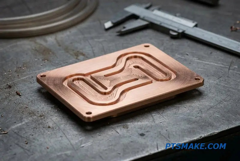
Skiving, which is a form of broaching6, creates fins by pushing a special cutting tool across a metal block. This method is incredibly efficient for producing straight, uniform fins. However, its main limitation is its one-directional nature. You can only create parallel fins with this process.
When CNC Machining is Essential
CNC machining provides far greater design flexibility. At PTSMAKE, we often recommend CNC for liquid cooling cold plates that require complex features. For example, if your design includes non-linear channels to target specific hot spots, integrated manifold features, or threaded ports, CNC is the only viable option. A CNC milled cold plate vs skived fin design allows for multi-depth zones, which can optimize coolant flow and thermal transfer.
Performance Considerations
While a broached heat sink is cost-effective, its performance is limited by its simple geometry. For advanced applications where every degree matters, the precision of a CNC-machined cold plate ensures the design intent is fully realized, maximizing thermal efficiency. The ability to create intricate internal structures is a significant advantage.
In short, skiving offers speed and cost-efficiency for simple, high-volume designs. However, for complex or high-performance liquid cooling cold plates requiring intricate geometries and integrated features, CNC machining is the superior and often necessary manufacturing method.
Flatness, Roughness, and Parallelism — The Three Surface Quality Metrics That Define Cold Plate Performance
For liquid cooling cold plates, optimal performance hinges on the quality of the mounting surface. Three geometric parameters are absolutely critical: flatness, surface roughness, and parallelism.
The Foundation of Thermal Transfer
These metrics directly influence the Thermal Interface Material (TIM) layer between the cold plate and the heat source. An imperfect surface forces a thicker TIM layer, which dramatically increases thermal resistance and reduces cooling efficiency.
Why Every Micron Matters
Controlling these features is not just about performance but also reliability. Uneven surfaces can create mechanical stress during assembly, potentially damaging sensitive electronic components. Precision machining is the key to achieving the required surface integrity.
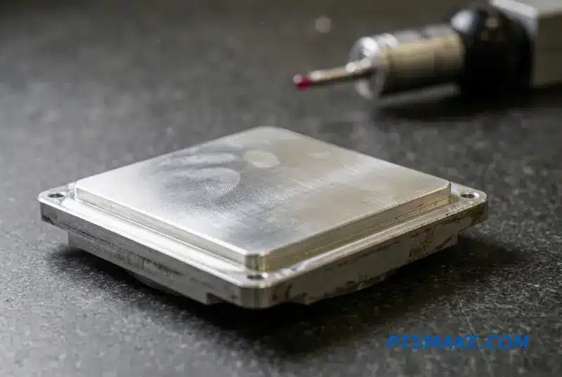
To achieve superior thermal performance, we must precisely control these three interrelated surface characteristics. Each one plays a distinct role in minimizing thermal resistance and ensuring mechanical stability for any liquid cooling cold plate assembly.
Flatness
A cold plate flatness specification defines how much a surface deviates from a perfect mathematical plane. High deviation creates large-scale gaps, requiring a thick TIM layer to fill them. We use a Coordinate Measuring Machine (CMM) for CMM inspection cold plate processes to ensure flatness is typically held within 0.001 inches per inch.
Surface Roughness
This measures the finer peaks and valleys on a surface. A controlled surface roughness cold plate contact face allows the TIM to spread thin and evenly. We often use a profilometer7 to measure this, targeting an Ra value between 0.8 and 1.6 μm for most applications.
Parallelism
A tight parallelism tolerance cold plate ensures the mounting surface is perfectly parallel to the base. This guarantees even clamping pressure across the entire component, preventing localized stress and ensuring a consistent TIM bond line thickness.
| Metric | Primary Impact | Measurement Method |
|---|---|---|
| Flatness | TIM Bond Line Thickness | CMM |
| Roughness | TIM Wetting & Adhesion | Profilometer |
| Parallelism | Clamping Stress & Uniformity | CMM |
Mastering flatness, roughness, and parallelism is fundamental for high-performance liquid cooling cold plates. These qualities directly govern thermal resistance and mechanical stability, ensuring your components operate coolly and reliably under load.
Fluid Port, O-Ring Groove, and Threaded Insert Design — Getting the Connection Right
A cold plate’s performance is ultimately determined by its connections. A leak can compromise an entire system, making robust fluid port design essential. Choosing the right port type is the first critical decision in any liquid cooling cold plates project to ensure a secure, leak-proof seal.
Understanding Port Thread Types
The most common thread types each serve different purposes. Selecting the incorrect one is a frequent cause of failure. We often guide clients on which standard best suits their application’s pressure, vibration, and serviceability needs. Cold plate leak prevention starts here.
Common Thread Standards
| Thread Type | Sealing Method | Common Applications |
|---|---|---|
| NPT | Tapered threads | Industrial fluid power |
| G / BSPP | Gasket or O-ring | Low-pressure systems |
| SAE J1926 | O-ring | High-pressure hydraulics |
Proper cold plate fluid port design ensures long-term reliability. The choice depends entirely on the system’s operational demands. For high-vibration environments, an O-ring sealed port like SAE is often a more reliable choice than an NPT thread cold plate connection.
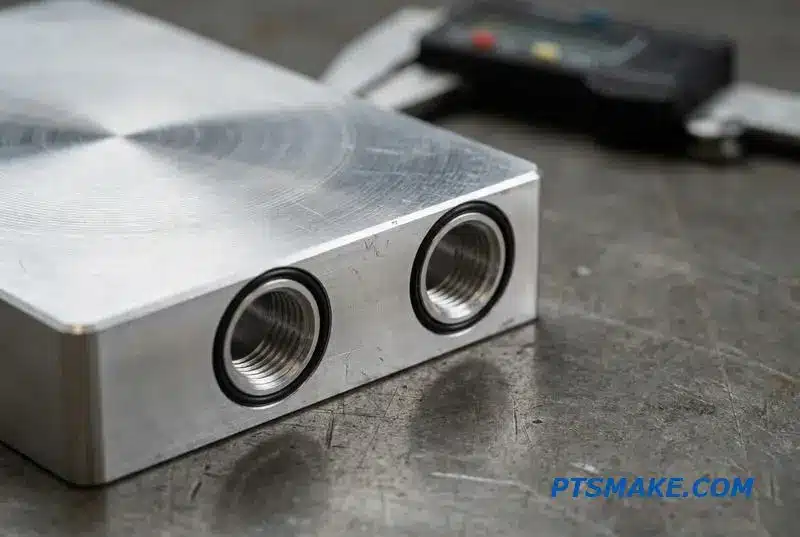
Beyond threads, the O-ring groove itself is critical. Its geometry dictates the seal’s effectiveness and longevity. The two primary designs, dovetail and rectangular, offer different advantages for an O-ring groove cold plate. A dovetail groove helps retain the O-ring during assembly, which is useful.
O-Ring Groove and Insert Considerations
However, machining a dovetail groove is more complex and can increase costs. A standard rectangular groove is often sufficient if assembly procedures are controlled. The material’s Durometer8 is also a key factor in calculating the correct compression for a lasting seal.
Threaded Insert Options
When working with softer materials like aluminum, threaded inserts are necessary to prevent thread stripping. Key-locking inserts provide superior torque resistance compared to wire-style inserts like Heli-Coils, making them ideal for connections that are frequently assembled and disassembled.
At PTSMAKE, our advanced CNC machining capabilities allow us to integrate these precise ports, O-ring grooves, and insert preparations directly into the cold plate body. This single-piece construction eliminates potential leak paths from secondary operations, greatly enhancing the reliability of liquid cooling cold plates.
Getting fluid connections right is fundamental to performance. Careful selection of thread types, precise O-ring groove design, and appropriate threaded inserts are non-negotiable for creating a reliable, leak-proof cold plate that protects sensitive electronic components from damage.
Prototyping Cold Plates on a CNC — Why Zero Tooling Cost Matters for Design Iteration
When developing custom liquid cooling cold plates, the biggest advantage of CNC machining is the elimination of tooling costs. Traditional methods like die casting or stamping require expensive molds and hard fixtures. These tools add significant upfront investment and lead time before you even see a single part.
The CNC Advantage: Speed and Flexibility
With CNC, we can machine a prototype directly from a solid block of aluminum or copper. This no tooling cold plate manufacturing approach means the first article can be ready in as little as 5-7 days. Changes are simple software adjustments, not expensive mold modifications.
Cost Comparison at a Glance
This table illustrates the initial setup differences. The main takeaway is that CNC avoids the high barrier to entry associated with traditional tooling, enabling a much more agile cold plate DFM prototype cycle.
| Feature | CNC Machining | Die Casting |
|---|---|---|
| Tooling Cost | $0 | Can exceed thousands per cavity |
| Initial Lead Time | 5-7 Days | 6-10 Weeks |
| Fixture Type | Basic Workholding | Custom Hard Tooling |
| Design Change Cost | Minimal (Programming) | High (Tool Rework) |
This streamlined process is ideal for getting functional prototypes into the hands of engineers quickly.
Unlocking Rapid Design Iteration
The real power of a CNC cold plate prototype process comes during design validation. A thermal engineer can test multiple internal channel geometries within a single prototyping cycle. This allows for empirical testing to find the optimal balance between coolant flow and thermal performance.
The Iteration Loop
With CNC, iterating is straightforward. An engineer can request a part with a serpentine channel, test it, and then request another with a parallel channel design. Since the cost is only tied to machine time and programming, this rapid cold plate iteration is incredibly cost-effective.
Comparing Iteration Cycles
This approach is nearly impossible with casting. Creating a new die-cast tool for each design variation is financially prohibitive and slow. At PTSMAKE, we help engineers leverage this flexibility to refine their designs based on real-world test data, ensuring the final product’s Heat Transfer Coefficient9 meets specifications.
| Aspect | CNC Prototyping | Die-Cast Prototyping |
|---|---|---|
| Testing Multiple Designs | Feasible in one cycle | Requires multiple expensive tools |
| Time Per Iteration | Days | Weeks or Months |
| Cost Per Iteration | Low (Programming + Material) | Very High (New Tooling) |
| Design Freedom | High | Limited by tooling constraints |
Ultimately, CNC machining de-risks the development process for liquid cooling cold plates.
CNC machining removes the significant barrier of tooling costs and delays. This enables fast, affordable, and flexible prototyping, allowing engineers to test and validate multiple designs for liquid cooling cold plates without the massive investment required by traditional manufacturing methods.
From One-Off Prototype to Production — Cold Plate Scaling Without Retooling
Scaling Liquid Cooling Cold Plates from a single unit to thousands doesn’t have to involve costly tooling. The path from cold plate prototype to production should be seamless. With CNC machining, the process is defined by flexibility, not by initial investment in molds or dies.
Our Scaling Pathway
At PTSMAKE, we have a clear, three-stage process. This structure allows our clients to validate designs with prototypes before committing to larger volumes. It provides a predictable timeline and cost structure as demand grows.
| Stage | Quantity | Typical Lead Time |
|---|---|---|
| Prototype | 5-50 pcs | 3-5 Business Days |
| Low-Volume | 50-1,000 pcs | 1-2 Weeks |
| High-Volume | 1,000+ pcs | 3-4 Weeks |
This model supports on-demand manufacturing perfectly.
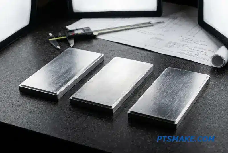
The primary advantage of CNC cold plate scalability is the absence of tooling costs. Unlike injection molding or die casting, you are not locked into a design by a multi-thousand-dollar mold. This allows for design iterations even after initial production runs without financial penalty.
The Power of Capacity, Not Molds
How do we scale? It’s simple: we allocate more machine time. For a prototype, one or two CNC machines might be used. For high volume CNC cold plate orders, we can dedicate a cell of machines to run parts concurrently. The manufacturing process itself remains identical.
This ensures that the tenth part is identical to the ten-thousandth. Maintaining this consistency is crucial. The high Repeatability10 of CNC machining means that thermal performance and mechanical fit are consistent across the entire production volume. This is a level of quality assurance that tooling-based methods can struggle with as molds wear over time.
For businesses, this de-risks the entire product launch. You can enter the market with low volume cold plate manufacturing and ramp up production only when sales data supports it. This aligns your manufacturing spend directly with revenue.
CNC machining offers a flexible, tool-less path for scaling cold plate production. This method allows you to move from prototype to high-volume orders by simply adding machine capacity, ensuring consistency and avoiding large upfront investments.
Material Certifications and Traceability — What Data Center OEMs Require From Cold Plate Suppliers
For data center OEMs, material certifications for liquid cooling cold plates are not just paperwork. They are essential for ensuring performance, reliability, and regulatory compliance. Full traceability is a baseline expectation, especially when components must meet strict thermal and mechanical specifications.
Key Traceability Documents
OEMs often require a complete documentation package. This confirms the material’s origin, composition, and properties. It eliminates guesswork and ensures every part meets the design intent. A failure in material quality can compromise an entire cooling system.
Mill Test Reports (MTRs)
The MTR is the foundational document. It provides a summary of the material’s physical and chemical properties directly from the mill that produced it.
| Document Type | Provided By | Purpose |
|---|---|---|
| Mill Test Report (MTR) | Material Mill | Certifies chemical/mechanical properties |
| Certificate of Conformance | CNC Supplier | Confirms part meets specifications |
| Compliance Docs (RoHS/REACH) | Material Mill/Supplier | Verifies environmental compliance |
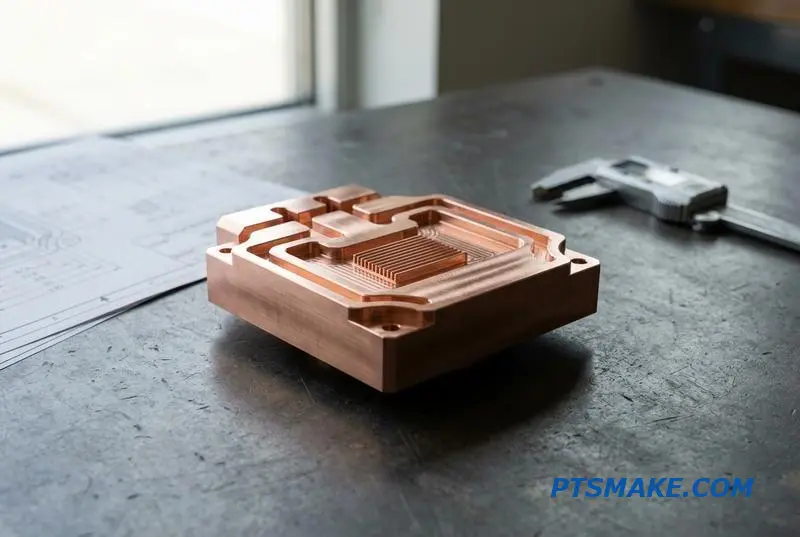
Understanding EN 10204 Certifications
For projects with stringent requirements, especially in European markets, EN 10204 certificates are critical. These provide different levels of validation. A Type 3.1 certificate is validated by the manufacturer’s authorized representative, independent of the manufacturing department. A Type 3.2 certificate adds another layer, requiring validation by a third-party inspection agency.
Chemical and Mechanical Verification
We often perform independent verification to ensure full compliance. This includes using methods like Spectrometry11 to confirm the chemical composition of materials like C11000 copper. This ensures complete C11000 copper traceability. Similarly, mechanical properties are tested to guarantee the material can withstand operational stresses.
| Certificate Type | Validation | Common Use Case |
|---|---|---|
| EN 10204 3.1 | Manufacturer’s Inspector | Standard industrial applications |
| EN 10204 3.2 | Third-Party Inspector | Critical components (aerospace, defense) |
RoHS and REACH Compliance
Beyond performance, environmental regulations are non-negotiable. Both RoHS and REACH compliance are mandatory for market access in many regions. As your CNC supplier, we ensure that all aluminum and copper alloys used in liquid cooling cold plates are fully compliant, providing the necessary documentation with every batch.
Full material traceability is fundamental for high-performance liquid cooling cold plates. From Mill Test Reports to EN 10204 certificates and RoHS compliance, this documentation provides the quality assurance that data center OEMs demand to ensure system reliability and regulatory adherence.
Cold Plate Design for Manufacturability — How to Save Cost Without Sacrificing Thermal Performance
When designing liquid cooling cold plates, small choices can lead to big cost increases. Focusing on Design for Manufacturability (DFM) is crucial. It ensures your design is efficient to produce without hurting its thermal capabilities. Simple oversights often inflate the final price unnecessarily.
At PTSMAKE, we guide our clients through these decisions. A few key adjustments in the design phase can significantly lower production costs. This approach focuses on practicality and avoids over-engineering where it provides no real benefit. Let’s look at some practical cold plate DFM guidelines.
Simplify Channel Geometry
Deep, narrow channels are a common cost driver in CNC machining. Machining channels deeper than 50mm often requires special tooling and slower cutting speeds, which increases machine time. Sticking to standard end mill lengths simplifies the process and reduces cost.
Specify Realistic Tolerances
One of the easiest ways to save on cost is by specifying achievable tolerances. While a tolerance of ±0.005mm might look good on paper, it’s often unnecessary. If a looser tolerance of ±0.02mm functions perfectly, choose that. Tighter tolerances require more careful setups and inspection.
| Design Choice | Low-Cost Approach | High-Cost Approach |
|---|---|---|
| Tolerance | Specify functional tolerances (e.g., ±0.02mm) | Unnecessarily tight (e.g., ±0.005mm) |
| Channel Depth | < 50mm (Standard tooling) | > 50mm (Special tooling) |
| Material Size | Design for standard bar stock dimensions | Requires custom-cut raw material blocks |
| Features | Integrate mounting holes into the body | Add secondary operations for features |
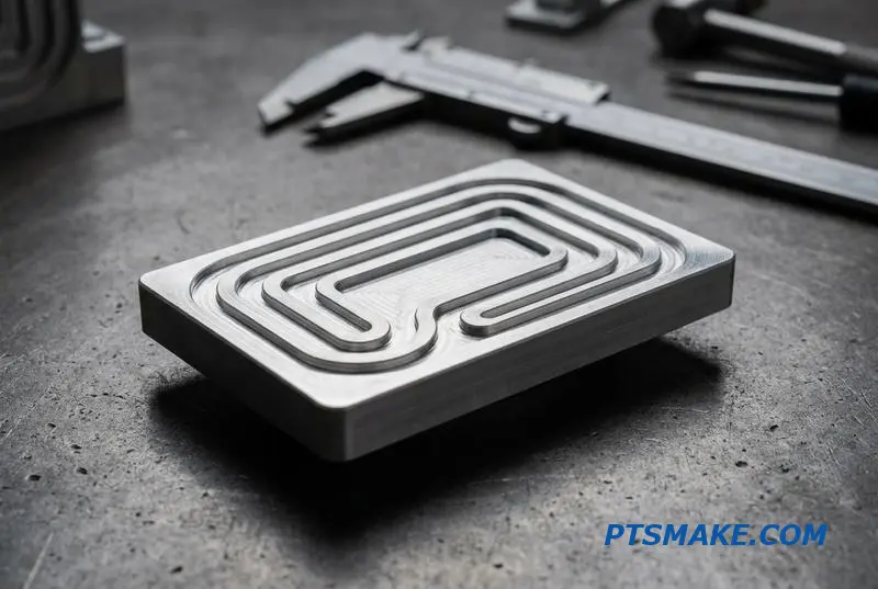
Optimizing your design is about balancing performance and manufacturability. For instance, designing parts to fit standard bar stock sizes minimizes material waste and the need for extra roughing operations. This simple step is a core principle for any cost optimization on liquid cooling plates. Each poor design choice incrementally adds to the unit price.
Consider Alternative Manufacturing Methods
For designs with very complex or deep internal channels, direct CNC machining might not be the most economical route. This is where alternative methods come into play. A multi-part construction using Brazing12 can be more cost-effective. This involves machining simpler components and then joining them.
Integrating Features
Another key aspect of a manufacturable cold plate design is feature integration. Whenever possible, integrate mounting holes and other features directly into the main body of the cold plate. This reduces the number of secondary operations, simplifies the manufacturing flow, and lowers the overall part cost. It’s a straightforward win for efficiency.
Smart DFM choices for liquid cooling cold plates, like optimizing channel depth, using realistic tolerances, and designing for standard materials, directly lower costs. These adjustments ensure manufacturability without sacrificing the thermal performance essential for your application.
Plate Thickness, Bow, and Residual Stress — The CNC Machining Challenges Nobody Talks About
Machining large, thin components like liquid cooling cold plates presents a unique challenge. When you remove material from one side of a 300mm x 200mm x 8mm plate, for instance, you’re not just cutting metal; you are releasing trapped residual stress. This causes the plate to bow or warp.
The Unseen Enemy
Residual stress is locked into raw material from its manufacturing process, like rolling or extrusion. Simply clamping it down and machining it to final dimensions often results in a part that warps as soon as it’s released from the fixture. This is a common failure point.
A Problem of Balance
Achieving the required flatness post-machining isn’t about force; it’s about control. The key is to manage stress release systematically throughout the entire manufacturing sequence, not just during the final cut.
| Challenge | Common Misconception |
|---|---|
| Plate Warpage | The material is "bad." |
| Lost Flatness | Clamping harder will fix it. |
| Inconsistent Results | The machine is not accurate enough. |
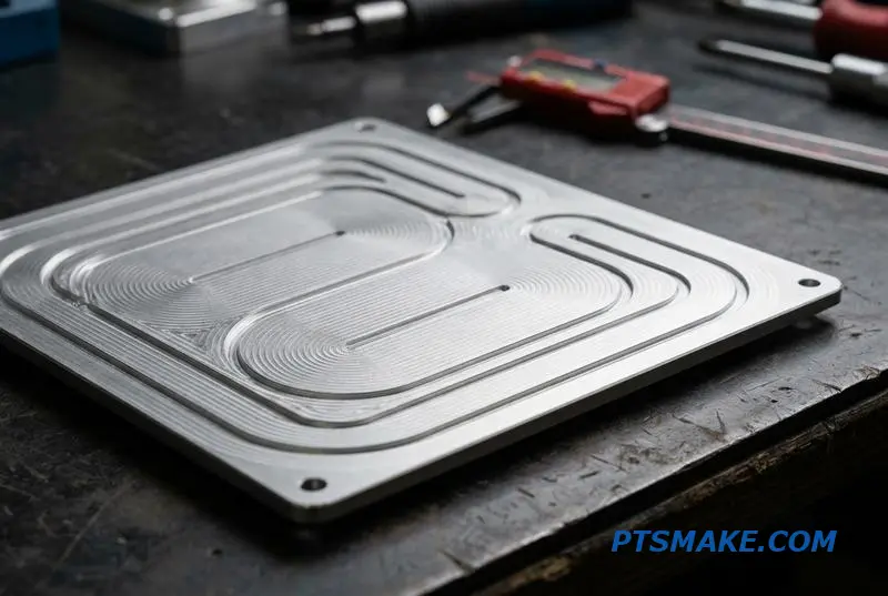
At PTSMAKE, we tackle thin cold plate machining warpage with a proven, multi-stage strategy. It’s a methodical approach that respects the material’s properties instead of fighting against them. Ignoring this process leads to scrapped parts and delayed timelines, something our clients can’t afford.
Our Three-Step Machining Strategy
First, we perform a roughing operation. We machine the plate close to its final shape but leave sufficient stock on all critical surfaces. This initial step removes the bulk of the material and releases the majority of the internal stress. The plate will likely warp at this stage, which is expected.
Next comes stress-relief annealing. The roughed part is heated to a specific temperature and then slowly cooled. This thermal cycle rearrates the material’s internal structure, relaxing nearly all remaining residual stress without altering its mechanical properties. It’s a critical reset for the material.
Finally, we execute the finishing passes. With the material now stable, we can machine the part to its final dimensions and achieve tight flatness tolerances. The internal stresses caused by the material’s Anisotropy13 have been neutralized.
Advanced Workholding for Precision
How you hold the part is just as important. For thin plates, traditional clamping can introduce new stress and distortion.
| Method | Best Use Case | Key Advantage |
|---|---|---|
| Vacuum Chuck | Final finishing operations | Uniform, low-pressure clamping |
| Double-Sided Tape | On a ground surface for initial ops | No side clamps to interfere |
| Low-Profile Clamps | Roughing stages on thicker stock | Secure hold for heavy cutting |
Achieving flatness on thin components like liquid cooling cold plates requires more than just precise cutting. It demands a systematic process that manages material stress through roughing, thermal annealing, and careful finishing, paired with appropriate workholding strategies to prevent distortion.
Custom Cold Plate Case Studies — Real Configurations and How They Were Machined
Theory provides a foundation, but real-world examples show how custom cold plates solve specific thermal challenges. I’ve selected a few anonymized projects to illustrate different approaches to design and manufacturing. These cases cover a range of complexities and production volumes.
Each project started with a unique problem. The solutions required different materials, machining strategies, and quality control processes to meet performance goals.
| Case Study Overview | Application | Key Feature | Primary Process |
|---|---|---|---|
| Case 1 | Networking Switch | Simple Single Channel | 3-Axis Milling |
| Case 2 | AI GPU | Copper Microchannels | 5-Axis Milling |
| Case 3 | High-Power IGBT | Serpentine Channels | CNC + Vacuum Brazing |
| Case 4 | Server Rack CDU | Integrated Manifold | 5-Axis + Drilling |
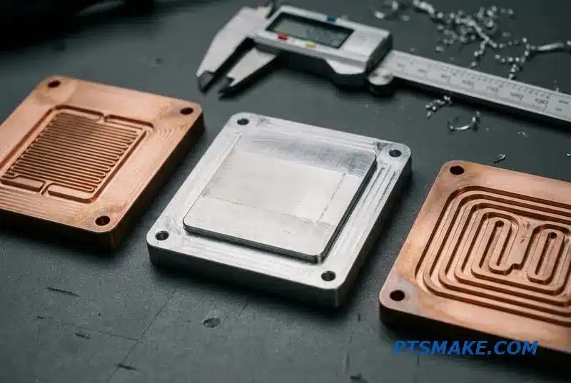
Let’s dive into the details of these custom cold plate examples. The simplest case was an aluminum single-channel plate for a networking switch prototype. It involved straightforward 3-axis milling. The focus was on rapid turnaround for functional testing, with basic leak and pressure checks confirming integrity.
In contrast, the copper microchannel cold plate for an AI server GPU was far more complex. This AI server cold plate machining project required 5-axis milling to create a dense Pin-fin14 array. Machining copper to such tight tolerances without deforming the fins is a significant challenge. We used specialized tooling and carefully controlled cutting parameters.
Two-Piece Brazed Construction
For a high-power IGBT module, we manufactured a two-piece brazed assembly. One plate was CNC machined with serpentine channels, and a flat cover was sealed over it using vacuum brazing. This process creates a leak-proof, robust bond, essential for high-pressure liquid cooling cold plates.
Hybrid with Integrated Manifold
A hybrid cold plate for a server rack required an integrated manifold. This design was machined from a single block using 5-axis milling combined with precision-drilled cross-channels. This eliminated potential leak points from fittings, creating a highly reliable component for a dense system.
These case studies show how manufacturing processes are tailored to application-specific thermal and mechanical requirements, from simple prototypes to complex, high-volume production parts.

This property is key to ensuring thermal interface reliability under temperature changes. ↩
Understanding this concept helps in specifying precise thermal management requirements for high-power electronics. ↩
This ratio helps quantify convective heat transfer performance across different liquid cooling cold plate designs. ↩
Explore how this solid-state process creates molecular-level bonds, essential for high-integrity thermal and structural applications. ↩
Understand how measuring micro-scale surface features directly influences thermal and mechanical component performance. ↩
Understanding this cutting method clarifies the geometric limits of skived fins versus multi-axis CNC milling. ↩
Learn how this instrument quantifies surface texture, ensuring parts meet critical thermal performance specifications. ↩
Understanding this helps select the right O-ring material for optimal sealing pressure and longevity. ↩
Understanding this coefficient is key to optimizing thermal performance in your liquid cooling cold plate designs. ↩
Understand how repeatability ensures consistent quality from the first part to the last, a critical factor in production scaling. ↩
Learn how this analysis technique verifies material purity and composition, ensuring quality control in precision manufacturing. ↩
Understand how this joining process enables complex geometries for high-performance thermal management solutions. ↩
Understanding this property helps predict and control material behavior during machining. ↩
Understanding pin-fin design helps optimize thermal performance in compact, high-heat applications. ↩