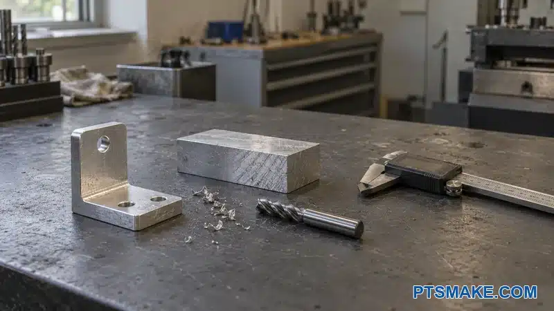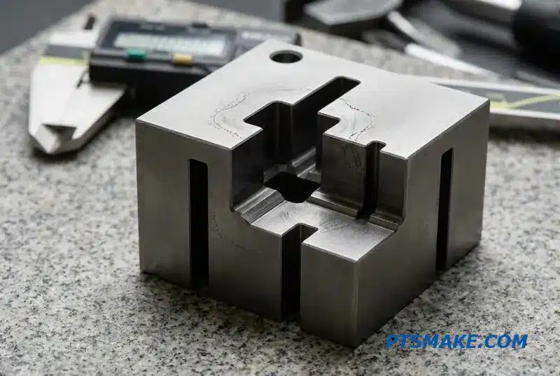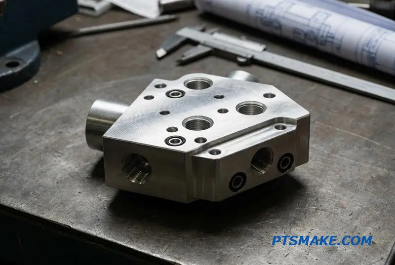

Sourcing humanoid robot arm links that meet tight tolerances feels like a constant battle. One misaligned bore, one warped link, and your entire arm assembly suffers from joint friction, vibration, and reduced payload.
CNC machined robot arm links are precision structural components connecting rotary joints, requiring bored bearing seats, weight-reduction pockets, and rib stiffeners. Materials like 6061, 7075, 2024 aluminum, and Ti-6Al-4V are selected based on stiffness, weight, and fatigue requirements.
I’ve worked on humanoid arm projects where a single 0.02mm bore misalignment caused early bearing failure. Below, I’ll share what truly matters when designing and machining robot arm links — from material picks to inspection.
The Anatomy of a Humanoid Robot Arm Link — Features That Require CNC Precision
Robot arm links and structural frames are more than simple connectors. They are the bones of the system, connecting two rotary joints. Each end features a precisely bored interface, often a bearing seat or bolt circle, that demands high accuracy for smooth operation.
Core Internal Features
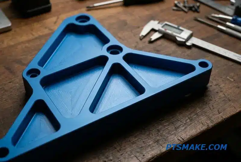
Inside, these links contain channels for cables and mounting points for sensors. We often machine weight-reduction pockets to lower inertia. Alignment dowel holes are also critical for assembly. Each feature contributes to the arm’s overall performance and reliability.
Required CNC Operations
Every feature requires a specific CNC process. Boring ensures the joint interfaces are perfectly aligned. Pocketing removes material for mass reduction without sacrificing strength. Drilling and tapping create precise threads for fasteners, a fundamental step for secure assembly.
| Feature | CNC Operation | Purpose |
|---|---|---|
| Joint Interface | Boring / Milling | Ensures concentricity and alignment |
| Weight Pockets | Pocketing | Mass reduction for lower inertia |
| Mounting Points | Drilling / Tapping | Secures sensors and components |
| Cable Channels | Milling | Protects and routes internal wiring |
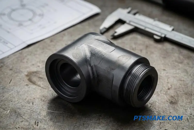
The difference between a standard industrial robot link and one for a humanoid robot is significant. Industrial links are often simple, box-section extrusions designed for rigidity and high payloads. Their primary function is strength over aesthetics or complex motion.
The Humanoid Arm Structural Component Design
Humanoid arms require a more sophisticated approach. They use thin-walled, sculpted links to mimic organic shapes and reduce weight. This complexity places extreme demands on CNC machining. The design must balance strength with a lightweight structure for dynamic movement.
Concentricity and Tolerances
For any robot arm, the link bore concentricity requirement is non-negotiable. Misalignment between the two joint interfaces can cause binding and premature wear. In a humanoid arm’s kinematic chain1, these small errors accumulate, leading to significant inaccuracies at the hand. We must hold tolerances tightly.
| Link Type | Primary Design Driver | Common Material | Machining Complexity |
|---|---|---|---|
| Industrial | Strength & Rigidity | Steel / Thick Aluminum | Low to Medium |
| Humanoid | Weight & Dynamics | High-Grade Aluminum / Titanium | High |
CNC precision is essential for robot arm links. From bearing seat concentricity to the exact placement of mounting bosses, every feature machined into the structural frame directly impacts the robot’s final performance, accuracy, and long-term reliability.
Material Selection for Arm Links — 6061, 7075, 2024, and Titanium Grade 5 Compared
Choosing the right material for robot arm links is a critical engineering decision. The choice impacts everything from performance and durability to manufacturing cost. Each material offers a distinct trade-off between strength, weight, and machinability. Making the wrong selection can lead to premature failure or unnecessary expense.
Common Material Candidates
We often work with four primary materials for these applications. Below is a quick overview of their key characteristics to guide your initial selection process for Robot Arm Links and Structural Frames.
| Material | Primary Advantage | Best For |
|---|---|---|
| 6061-T6 Aluminum | Cost-Effective & Machinable | General-purpose, non-critical links |
| 7075-T6 Aluminum | High Strength | High-performance, load-bearing arms |
| 2024-T351 Aluminum | Excellent Fatigue Resistance | Aerospace and high-cycle robotics |
| Titanium Grade 5 | Strength-to-Weight Ratio | Mission-critical, space-constrained parts |
This comparison sets the stage for a deeper analysis of each material’s specific strengths and weaknesses in robotic applications.
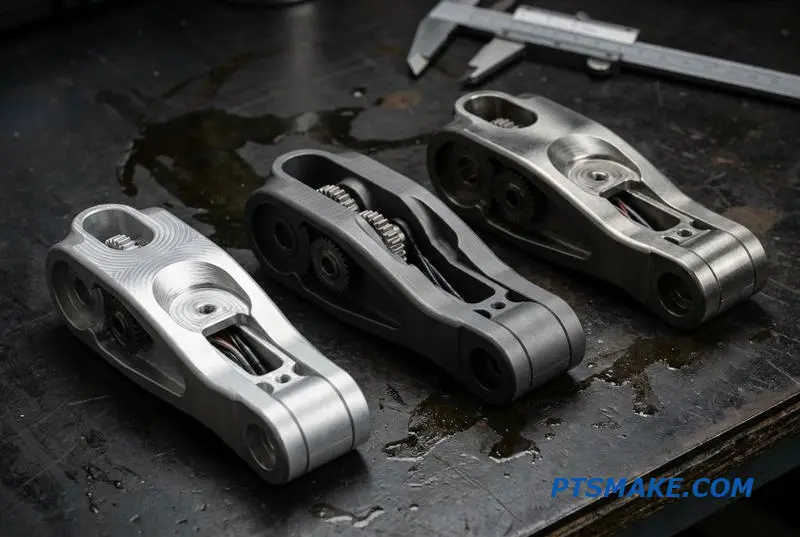
At PTSMAKE, we frequently machine Robot Arm Links and Structural Frames from these four materials. Each has a distinct personality on the CNC machine and a different performance profile in the final assembly.
6061-T6 vs. 7075-T6
For most structural components, 6061-T6 is the reliable workhorse. It machines cleanly, is widely available, and provides good strength for its cost. However, when a client requires higher performance, we often recommend 7075-T6. Its yield strength is nearly double that of 6061-T6, making it a clear choice for high-stress applications. The trade-off is its tendency to warp during machining, which requires careful planning and stress-relieving steps.
High-Performance Alternatives: 2024-T351 and Titanium
For high-end robotics, 2024-T351 aluminum offers an interesting middle ground. Its excellent Fatigue resistance2 makes it superior to 7075 for components under cyclic loading. When absolute performance is non-negotiable, Titanium Grade 5 (Ti-6Al-4V) is the premium option. It offers a strength-to-weight ratio that aluminum can’t match, but its material and machining costs are significantly higher.
| Property | 6061-T6 | 7075-T6 | 2024-T351 | Titanium Gr 5 |
|---|---|---|---|---|
| Density (g/cm³) | 2.70 | 2.81 | 2.78 | 4.43 |
| Yield Strength (MPa) | 276 | 503 | 324 | 830 |
| Elastic Modulus (GPa) | 68.9 | 71.7 | 73.1 | 113.8 |
This data, based on our material testing, shows the clear performance jumps between each option.
The selection of a material for robot arm links is a balancing act. It requires a clear understanding of the application’s demands against the constraints of budget and manufacturing complexity. No single material is universally best; the optimal choice is always application-specific.
Structural Dynamics — How Link Stiffness Affects Robot Path Accuracy and Payload
The Unseen Factor in Precision
In robotics, we often focus on motor torque and control algorithms. However, the structural stiffness of the robot’s links is just as critical. A seemingly rigid arm can flex under load, introducing errors that software alone cannot easily correct. This is especially true for Robot Arm Links and Structural Frames.
How Bending Compromises Performance
Even a millimeter of deflection in a robot arm link can translate to significant deviation at the end-effector. This affects path accuracy during motion and positioning repeatability. It also directly limits the effective payload, as the arm struggles to maintain its programmed path under weight.
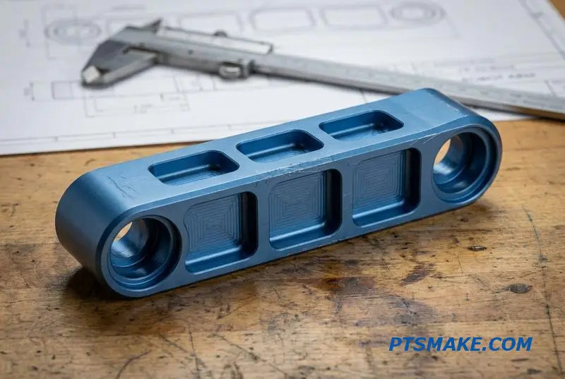
The Physics of Link Stiffness
A link’s first natural frequency, a measure of its tendency to vibrate, is directly related to its stiffness. Low stiffness results in a lower natural frequency, making the arm prone to oscillation during acceleration or deceleration. This vibration degrades performance and can reduce the component’s lifespan.
Static Deflection and Compounded Error
Furthermore, static deflection under load directly adds to the robot’s kinematic error. The control system must compensate by adjusting joint angles, which consumes available motor torque. This effectively reduces the robot’s usable payload, especially at full extension where leverage is greatest.
Material and Design Solutions
Material choice is a primary factor. As our tests with clients show, switching from 6061 to 7075 aluminum for a link of the same mass can increase stiffness by nearly 50%. This improves the natural frequency and reduces deflection significantly.
| Material | Relative Stiffness (E) | Density (g/cm³) | Application Note |
|---|---|---|---|
| 6061-T6 Aluminum | 1.0x | 2.70 | Good general-purpose choice. |
| 7075-T6 Aluminum | 1.04x | 2.81 | Higher strength and stiffness. |
| Carbon Fiber | ~1.5x – 2.5x | ~1.60 | Excellent stiffness-to-weight ratio. |
Beyond materials, advanced CNC machining allows us to add internal ribs and gussets. These features increase the component’s section modulus3 without significantly increasing mass, providing a far stiffer structure for critical Robot Arm Links and Structural Frames.
Robot arm link stiffness is fundamental to dynamic performance. It directly governs vibration, path accuracy, and payload capacity. Optimizing it requires a careful balance of material selection and intelligent design, often realized through precision CNC machining techniques like integrated stiffening ribs.
Joint Interface Machining — Bearing Bores, Dowel Holes, and Bolt Circles at Both Ends
The performance of robot arm links and structural frames hinges on one critical factor: the precise alignment of joint interfaces at each end. Misalignment introduces friction, accelerates wear, and degrades the robot’s accuracy. Getting this right is non-negotiable in high-performance applications.
The Challenge of Parallelism
For a forearm link, if the two bearing bores at opposite ends are misaligned by more than 0.02mm in parallelism, problems arise quickly. This small deviation leads to increased joint friction and premature bearing failure. It directly impacts the operational life and reliability of the entire system.
Critical Machining Features
The key features requiring perfect alignment are the bearing bores, dowel pin holes, and the threaded bolt circle. Each plays a distinct role in securing the joint and ensuring smooth motion.
| Feature | Primary Function | Machining Priority |
|---|---|---|
| Bearing Bores | Provide seats for bearings, defining the axis of rotation. | Highest |
| Dowel Holes | Ensure precise, repeatable location of mating components. | High |
| Bolt Circles | Securely clamp the joint assembly together. | High |
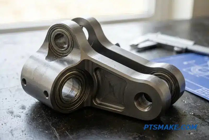
Achieving such tight tolerances across the long span of a robot arm link is a significant challenge. The solution lies in minimizing the number of setups. Every time a part is re-clamped, the risk of introducing datum shift error increases. This is where strategic machining choices become paramount.
Single-Setup Machining Strategy
At PTSMAKE, we prioritize single-setup machining for these components. By using a horizontal machining center (HMC), we can access and machine both ends of the link without re-fixturing. This method uses a common set of datums for all critical features, effectively locking in their geometric relationship. A tombstone fixture on an HMC further enhances this process for robotics parts.
The Power of GD&T
This is where Geometric Dimensioning and Tolerancing (GD&T)4 becomes the language of precision. Callouts for parallelism and true position on the engineering drawing remove ambiguity. They tell us exactly how the bearing bores, dowel holes, and bolt patterns must relate to each other and to the primary datums.
| Machining Method | Alignment Accuracy | Efficiency |
|---|---|---|
| Single Setup (HMC) | Excellent | High |
| Multiple Setups | Good to Poor | Moderate |
| Manual Transfer | Poor | Low |
This approach ensures that what the designer intended is what we manufacture. For joint interface machining on a robot link, controlling parallelism and position is not just a goal; it is a fundamental requirement for function.
Achieving sub-0.02mm parallelism in robot arm links is essential for performance. This precision is best realized through single-setup strategies on a horizontal machining center, guided by clear GD&T specifications, which ensures longevity and operational accuracy for the final assembly.
Fixturing Challenges for Long, Thin Robot Arm Links — Deflection, Chatter, and Stress Relief
Machining long, thin Robot Arm Links and Structural Frames is not straightforward. The part’s geometry makes it susceptible to several issues that can compromise precision. These slender components tend to deflect under cutting forces, vibrate uncontrollably, and warp as internal stresses are released during machining.
Key Machining Hurdles
Managing these factors is crucial for success. Without the right strategy, you risk scrapping expensive material and missing deadlines. It demands a deep understanding of material behavior and advanced fixturing techniques. At PTSMAKE, we’ve refined our approach to handle these delicate parts.
Common Problems and Fixturing Goals
| Problem | Fixturing Goal |
|---|---|
| Deflection | Distribute clamping force evenly without distortion |
| Chatter | Dampen vibrations at the source |
| Stress Release | Allow material to stabilize before final cuts |
Each challenge requires a specific solution. A one-size-fits-all approach to long part fixturing simply doesn’t work. The key is to anticipate these issues before the first cut is even made.
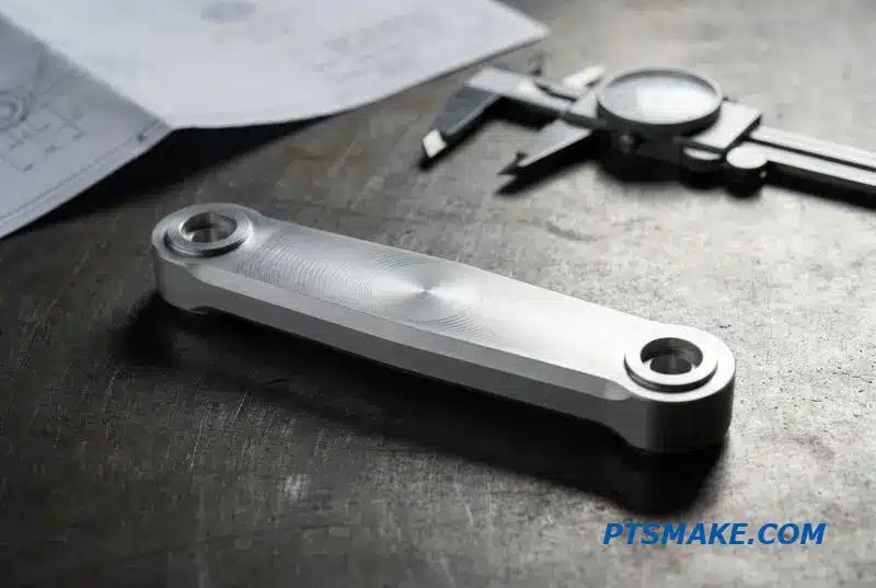
To overcome these challenges, we have to look beyond standard workholding. For long robot arm links, minimizing clamping-induced distortion is our first priority. We often use custom soft jaws or vacuum fixturing to provide broad, even support without crushing or bending the workpiece.
Managing Internal Stress
Residual stress is a major factor. For materials like 6061-T6 aluminum, we machine a rough profile, then allow the part to rest and stabilize. A better approach is using T651 temper aluminum, which is stress-relieved at the mill. For high-strength 7075 aluminum, machining from a pre-stretched billet is often the most reliable solution.
A Practical Example
I recall a 500mm forearm link that warped 0.15mm after roughing. The issue was internal stress release. We solved it by implementing a stress-relief heat treatment before the final machining passes, which kept the part stable and within its tight tolerance requirements.
Suppressing Chatter
Thin walls on these links are prone to vibration, or chatter, which ruins the surface finish. This happens when the cutting tool excites the part’s resonant frequency5. Based on our internal testing, using variable-pitch end mills is highly effective at suppressing this chatter, ensuring a smooth, accurate final surface.
Successfully machining long robot arm links requires careful fixture design, strategic stress relief, and advanced chatter suppression techniques. Overlooking these critical steps often leads to scrapped parts, project delays, and increased costs, which we always aim to avoid for our clients.
Rib Design for Stiffness — Optimizing Pocket Geometry in CNC Machined Links
Ribs are the most efficient way to boost link stiffness without a significant mass penalty. For components like robot arm links and structural frames, selecting the right rib pattern is critical. The geometry directly influences how the part responds to operational loads.
Rib Patterns for Targeted Stiffness
Longitudinal ribs are ideal for resisting bending forces along the main axis. Cross ribs, on the other hand, significantly improve torsional rigidity. For complex load paths, especially in thin-wall ribbing strategies, a lattice or diamond pattern distributes stress more evenly across the structure.
Stiffness Comparison: Ribbed vs. Unribbed
Our tests show how effective even simple ribbing can be. A link with three longitudinal ribs can achieve more than double the bending stiffness of an unribbed shell of the same mass, a key factor in pocket geometry optimization for lightweight parts.
| Link Configuration | Mass (kg) | Relative Bending Stiffness |
|---|---|---|
| Unribbed Shell (3mm wall) | 1.25 | 1.0x |
| 3 Longitudinal Ribs | 1.25 | 2.3x |
| Ribbed with Cross-Bracing | 1.35 | 2.9x |
This data highlights the power of rib design in CNC machining for robot links.
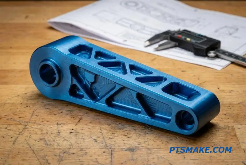
Key Design Guidelines for Machinability
Successful rib design balances structural needs with manufacturing reality. A common rule is a rib height-to-thickness ratio between 5:1 and 10:1. This range provides substantial stiffening without making the ribs too thin and prone to vibration during machining or failure in use.
Fillets and Pocket Ratios
A minimum fillet radius at the rib’s base is crucial for stress distribution. We typically recommend R2-R4mm to prevent stress concentrations and allow for proper tool access. For pockets, we advise a maximum depth-to-width ratio of 4:1 to avoid significant tool deflection and maintain tolerance.
Machining Feasibility: 3-Axis vs. 5-Axis
The complexity of your ribbing strategy often determines the machining approach. Standard 3-axis machines are perfect for parts with parallel longitudinal or cross ribs. The tool approaches from one direction, making it efficient for simple pocket geometry optimization.
However, for lattice patterns, angled ribs, or deep pockets with tapered walls, 5-axis machining is necessary. It allows the tool to approach the workpiece from different angles, reducing tool chatter, improving surface finish, and enabling more complex, lightweight designs that would be impossible otherwise. This is especially true when dealing with high Torsional stiffness6 requirements.
Strategic rib patterns are fundamental for enhancing the stiffness-to-weight ratio in CNC machined parts. Following key design guidelines and selecting the right machining process—3-axis for simplicity or 5-axis for complexity—is essential for achieving optimal performance in robot arm links and structural frames.
Internal Threads in Thin-Wall Links — Boss Design and Thread Engagement Depth
In designing robot arm links and structural frames, we often use thin walls of 2-4mm to save weight. However, this creates a challenge for threaded interfaces needed for sensors or covers. A simple tapped hole in a thin wall provides insufficient thread engagement, leading to potential failure.
The Role of a Boss
The solution is to add a machined boss. A boss is a raised cylindrical feature that provides the necessary material thickness for a strong, reliable threaded connection. It effectively localizes material where strength is needed without adding excessive weight to the entire component.
Essential Design Rules
For aluminum parts, I follow two key rules for threaded boss design in thin wall applications. These guidelines ensure the connection can withstand specified torque without stripping.
| Guideline | Specification | Rationale |
|---|---|---|
| Engagement Depth | Min. 1.5x nominal thread diameter | Ensures sufficient thread surface area to handle load. |
| Boss Outer Diameter | Min. 2x nominal thread diameter | Prevents thread stripping by providing adequate support material. |
For example, an M4 thread requires a minimum of 6mm of engagement. On a 3mm wall, the boss must stand at least 3mm proud.
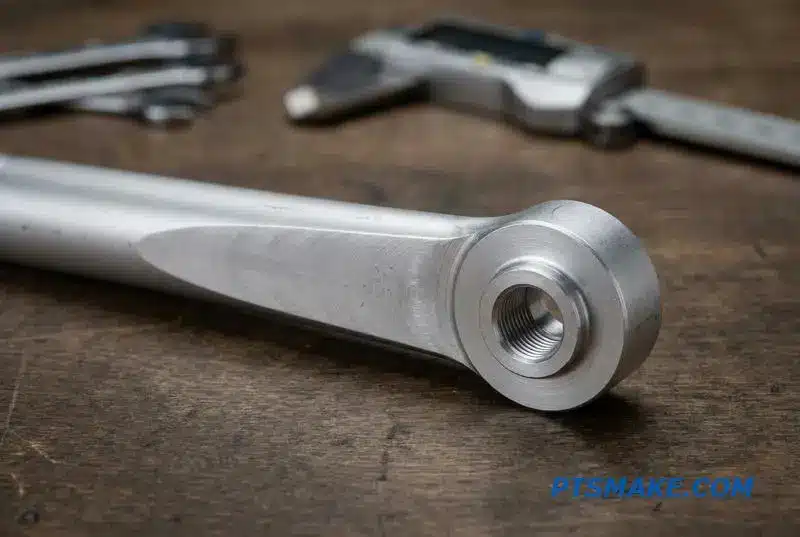
Beyond the basic design rules, successful implementation depends on smart machining practices and considering the component’s lifecycle. We must account for both manufacturing realities and long-term durability, especially for parts that are frequently assembled and disassembled during research and development.
Machining and Durability Considerations
When machining bosses on curved or angled surfaces of robot arm links, a spot drill is essential. It creates a small, precise starting point that prevents the main drill from "walking" or wandering off-center. This small step ensures the final tapped hole is perfectly concentric and perpendicular.
Rigid Tapping vs. Thread Milling
For creating the threads, we choose between rigid tapping and thread milling. Rigid tapping is faster and cost-effective for standard threads. However, in thin-wall aluminum with long engagement threads, thread milling offers better control, reduces tool pressure, and minimizes the risk of material distortion.
Enhancing Thread Life with Inserts
For aluminum links that will be disassembled repeatedly, the native threads will wear out. To prevent this, we install steel inserts like Helicoils or Keenserts. These inserts provide a durable, wear-resistant steel thread surface, protecting the softer aluminum from damage and avoiding stress concentration7.
Proper boss design is crucial for reliable threaded connections in thin-wall components. Adhering to engagement depth and outer diameter rules, using correct machining techniques, and reinforcing threads with inserts for aluminum parts ensures robust performance for robot arm links and structural frames.
Surface Finish Requirements for Robot Arm Links — Why Cosmetic Specs Drive Cost
When a drawing for a robot arm link doesn’t specify a surface finish, shops often default to an as-machined surface. This means tool marks may be visible (typically Ra 1.6-3.2μm). While functional, it often doesn’t meet the aesthetic standards for visible external parts.
Understanding the Finish Progression
Cosmetic choices directly impact the final cost. Each step adds labor, materials, and processing time. Simply moving from an as-machined finish to a bead blast for a matte texture introduces a new operation. The cost increases further with protective coatings.
Common Finishes and Their Cost Impact
Here is a quick breakdown of how different finishes for a surface finish robot arm link affect the budget. The cost escalates with each added layer of aesthetic appeal or functional protection.
| Finish Type | Primary Purpose | Relative Cost Adder |
|---|---|---|
| As-Machined | Baseline | None |
| Bead Blast | Matte Aesthetic | Low |
| Chemical Conversion | Corrosion Resistance | Low to Medium |
| Type II/III Anodizing | Wear & Corrosion | Medium to High |
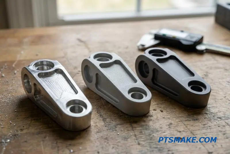
Choosing the right surface finish for Robot Arm Links and Structural Frames requires balancing function, aesthetics, and cost. Over-specifying cosmetic details is a common mistake that inflates manufacturing expenses without adding real value to the final product.
Strategic Specification for Cost Control
Engineers can significantly reduce CNC surface finish spec cost with careful planning. One key area is masking. Before any coating process, all threaded holes and precision bearing bores must be masked. This prevents the coating from altering critical dimensions, but it is a manual, time-consuming step.
Another important strategy is selective finishing. Specify cosmetic treatments like a bead blast aluminum robotic part only where they are functionally required. This usually means external faces that are visible on the assembled robot. There is no need for a perfect finish on internal pockets that will be covered. Similarly, a hard anodize structural frame should be specified for wear resistance, not just looks.
Best Practices for Specifying Finishes
Applying finishes only where necessary is crucial for optimizing costs. This approach also simplifies the manufacturing process. The chemical process of passivation8 in conversion coatings, for example, is best applied to surfaces that actually require its protective benefits.
| Do | Don’t |
|---|---|
| Specify finish on external faces only. | Apply cosmetic finishes to internal, hidden pockets. |
| Clearly call out masking for threads/bores. | Assume the shop will mask critical features. |
| Use bead blasting for uniform matte texture. | Expect bead blasting to hide deep tool marks. |
Careful specification is critical. Applying cosmetic finishes only to visible external faces and masking critical features like threads and bores prevents unnecessary costs. This ensures the robot arm links meet both aesthetic and functional requirements without budget overruns.
Prototype Iteration Cycle for Robot Arm Links — From Drawing to First Link in Weeks
Hardware startups thrive on fast iteration. For robot arm links, you might need to change a pocket shape, add a mounting boss, or adjust a hole pattern. Getting that new physical part in days, not weeks, is a significant competitive advantage.
The Advantage of Tooling-Free Production
CNC machining is perfectly suited for this rapid development. Unlike injection molding or casting, there is no tooling lead time. The process is direct from a digital model to a physical part, allowing for quick adjustments and fast turnaround CNC robot parts.
A Realistic Prototyping Timeline
Based on our work with robotics clients, a typical iteration cycle follows a clear path. This speed is crucial for meeting aggressive hardware startup robot development lead times.
| Day | Action |
|---|---|
| 1 | Client submits revised drawing |
| 2 | We provide DFM feedback |
| 3-5 | Machine and inspect the new link |
| 6-7 | Ship the finished part |
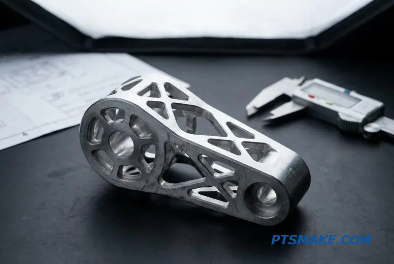
The core of rapid robot link prototype iteration lies in the flexibility of the CNC process. When a design for a robot arm link is updated, the changes are primarily digital. This is fundamentally different from methods requiring physical molds or dies.
The True Cost of Prototyping: Flexibility vs. Tooling
For a minor geometry change, updating the CAM program in software like Fusion 360 or Mastercam is straightforward. We simply adjust the toolpaths. Often, the same fixture can be used, eliminating any setup delays. This process is a core example of subtractive manufacturing9, where material is precisely removed from a solid block.
Prototyping Economics
This agility becomes even more critical for humanoid robot projects that can have 10-20 different link geometries. The CNC prototyping vs. tooling cost is dramatically different. Consider three design iterations for a single part:
| Manufacturing Method | Iteration 1 | Iteration 2 | Iteration 3 | Total Prototype Cost |
|---|---|---|---|---|
| CNC Machining | $150 | $150 | $150 | $450 |
| Die Casting | $8,020 | $8,020 | $8,020 | $24,060 |
This comparison clearly shows how CNC machining empowers startups to refine designs without incurring prohibitive tooling costs and delays on structural frames and links.
For robot link prototype iteration, CNC machining provides unmatched speed and cost-effectiveness. It removes tooling barriers, allowing hardware startups to refine designs quickly and affordably, which is a decisive advantage in fast-paced hardware development projects.
Scaling Link Production — From Prototype to 1,000 Units on the Same CNC Program
One of the greatest strengths of CNC machining for Robot Arm Links and Structural Frames is its natural scalability. The same CAM program that makes your first prototype is the foundation for producing a thousand units. The core geometry and toolpaths remain identical.
From Design Validation to Production Efficiency
The transition isn’t about re-engineering the program; it’s about refining operations. During prototyping, the focus is on validating the design and ensuring accuracy. For production, the focus shifts to optimizing speed and reducing cost per part.
Key Focus Shift
This table illustrates the change in priorities from a single prototype to a full production run. It highlights how the same basic process is adapted for different manufacturing goals.
| Aspect | Prototype Phase Focus | Production Phase Focus |
|---|---|---|
| Primary Goal | Design Validation & Fit | Cost & Speed Efficiency |
| Toolpaths | Conservative Speeds | Optimized Cycle Time |
| Workholding | Single Part Fixture | Multi-Part Fixturing |
| Material | Standard Stock Size | Bulk Quantity Discounts |
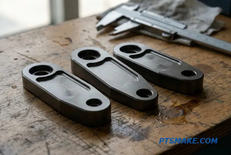
Scaling production is an operational task, not a programming one. We achieve significant efficiency gains by focusing on three key areas. This process allows us to handle orders from 10 units to 500 on the same setup without any mold investment.
Cycle Time Optimization
First, we optimize the toolpaths for speed. This includes increasing feed rates during roughing passes and using high-feed mills to remove material faster. We also meticulously reduce "air cuts," where the tool moves without cutting, saving valuable seconds on every part.
Multi-Part Fixturing and Automation
Next, we implement multi-part fixturing, or "ganging." We can load two to four forearm links onto a single fixture in one machining center. This reduces the time lost to tool changes and operator intervention per part. The machine’s ability to execute these paths precisely relies on a process called Interpolation10.
Real-World Reductions
Based on our tests, a complex forearm link that takes 90 minutes per part during prototyping can be reduced to just 45 minutes in production. This 50% reduction comes purely from toolpath optimization and multi-part fixturing. Additionally, material costs often drop by around 30% from billet quantity discounts.
The same CNC program scales from prototype to production. Efficiency is gained through operational refinements like cycle time optimization and multi-part fixturing, not new programming. This method lowers costs and provides incredible flexibility for any order size.
Quality Inspection of Long Robot Arm Links — CMM Strategies for 500mm+ Parts
Inspecting long robot arm links over 500mm presents unique challenges. Gravity itself can cause the part to sag or deflect, leading to inaccurate measurements. A solid Coordinate Measuring Machine (CMM) strategy is not just recommended; it’s essential for verifying critical features like bearing bore parallelism.
Proper Fixturing and Machine Selection
The first step is always proper setup. You must support the part correctly to get reliable data. We also need to ensure the CMM has enough travel to measure the entire length without re-fixturing, which introduces error.
Key Setup Parameters
A successful CMM inspection for long robot links starts with these fundamentals. They form the foundation for every subsequent measurement and directly impact the final quality report.
| Strategy | Requirement | Purpose |
|---|---|---|
| Fixturing | Support at specific calculated points | Minimize gravity-induced sag/deflection |
| CMM Size | X-axis travel > part length (e.g., 800mm+) | Accommodate the full part dimension |
| Probing | Multi-point checks at various angles | Ensure true bore concentricity and form |
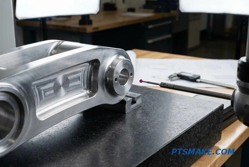
To ensure a reliable bearing bore parallelism measurement, proper support is non-negotiable. We often use Airy points11 for fixturing, which are specific locations that minimize bending deflection. For a uniformly distributed beam, these are located 0.223L from each end.
Understanding Measurement Uncertainty
A typical CMM might have a measurement uncertainty of 2.5μm + L/300. For a 500mm part, this calculates to approximately ±3.2μm. For a common parallelism tolerance of ±25μm, this level of uncertainty is entirely acceptable and provides a high degree of confidence in the results.
Defining the First Article Inspection Report (FAIR)
A detailed FAIR is crucial for parts like these. At PTSMAKE, we ensure our reports capture all critical-to-function dimensions to provide a complete picture of the part’s quality. This leaves no room for ambiguity when confirming that complex robot arm links meet specification.
| Inspection Point | Specification Detail | Rationale |
|---|---|---|
| Bore Diameter | 4 points at 3 depths | Verifies true roundness and cylindricity |
| Bore Parallelism | Axis-to-axis over the full length | Critical for smooth robotic joint alignment |
| Dowel Hole Position | True Position relative to datums | Ensures precise and repeatable assembly |
| Overall Length | End-to-end envelope dimension | Confirms basic dimensional accuracy |
A robust CMM strategy for long robot arm links requires correct fixturing, an understanding of measurement uncertainty, and a comprehensive FAIR. These elements ensure that parts function perfectly within their final robotic assembly, meeting all design specifications for precision and reliability.

Understand how this principle governs robotic motion and structural integrity. ↩
Understanding this concept is key to designing durable, long-lasting robotic components under cyclic loads. ↩
Explore how this geometric property is key to designing stronger, lighter structural parts without changing materials. ↩
Understand how this symbolic language ensures parts function correctly in complex assemblies like robot arms. ↩
Understanding this concept helps predict and prevent machine tool chatter for better surface finishes. ↩
Learn how this property helps prevent twisting in structural components under complex loads. ↩
Understanding this helps prevent premature part failure at geometric discontinuities like threads and corners. ↩
Understand how this chemical process enhances material corrosion resistance, a key concept for durable engineering design. ↩
Explore how this core principle impacts material choice, part strength, and surface finish in prototyping. ↩
Understanding interpolation helps clarify how CNC machines translate digital code into the smooth, precise physical movements required for complex parts. ↩
Understanding these points is crucial for minimizing measurement error in long, flexible parts. ↩