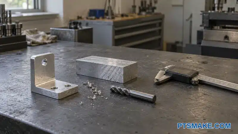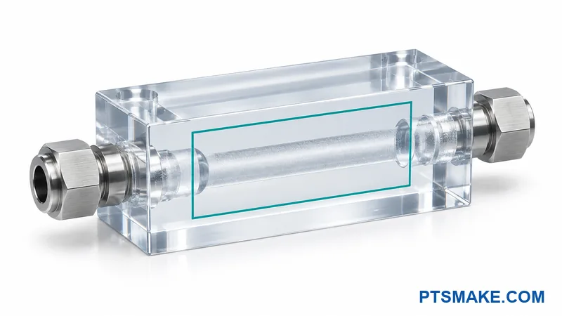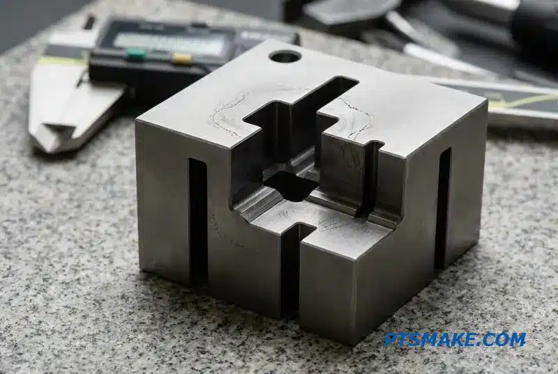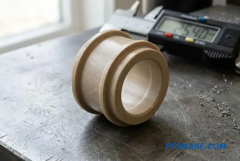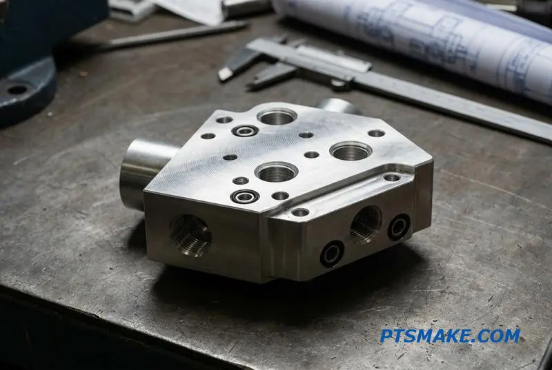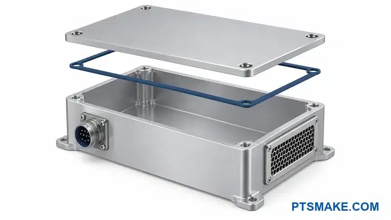

A single leaking valve in your 40-rack AI cluster can shut down an entire row. While cold plates get all the attention, valves are the moving parts that actually control coolant flow, pressure, and shutoff—and they fail first.
CNC machining for liquid cooling valves requires sub-micron clearances on spools, seats, and sleeves to prevent internal leakage. Precision in sealing geometry, surface finish (Ra ≤ 0.2 μm), and concentricity (≤ 0.025mm TIR) directly determines valve reliability and cooling system uptime.
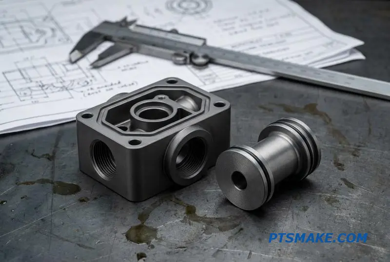
I’ve worked with engineering teams building liquid cooling loops for data centers, and the valve is always where problems start. In this guide, I’ll walk you through how each valve component should be machined—from bodies to spools to seats.
Why Valve Precision Determines Liquid Cooling System Reliability
In the race to cool high-density data centers, components like cold plates get all the attention. However, valves are the system’s active gatekeepers. They control coolant flow, manage pressure, and provide critical shutoff, making them essential for operational stability.
The Overlooked Failure Point
A single leaking valve in a 40-rack AI cluster can trigger a shutdown of the entire row, leading to catastrophic downtime. This highlights a critical truth: the reliability of a multi-million dollar system often hinges on the precision of its smallest mechanical components.
Focus on Machining Precision
The manufacturing precision of a valve, especially its internal sealing geometries, is the highest-risk factor in liquid cooling reliability. Effective liquid cooling valve machining ensures flawless performance over millions of cycles.
| Valve Type | Primary Function |
|---|---|
| Proportional Control | Modulates flow rate |
| Ball / Butterfly | On/Off isolation |
| Check Valve | Prevents backflow |
| Solenoid Valve | Electro-mechanical control |
The Mechanics of Valve Failure
A valve’s reliability isn’t just about preventing leaks. It is about maintaining performance specifications under constant thermal and pressure cycling. Imperfections invisible to the naked eye can lead to premature failure, inconsistent flow control, and operational instability over time.
The Role of Sealing Surfaces
The internal sealing surfaces are where precision matters most. In our testing, we found that even microscopic scratches or deviations on a valve seat can create a path for slow leaks. These minor issues can escalate into major system failures under high pressure.
Flow Rate and Thermal Management
Inconsistent valve performance directly impacts thermal management. A valve that fails to deliver the specified Volumetric flow rate1 can cause processors to overheat and throttle, degrading the performance of the entire system. Precision machining ensures that each valve operates exactly as designed.
| Machining Attribute | Impact on Reliability |
|---|---|
| Surface Finish | Determines seal integrity and wear resistance. |
| Geometric Tolerance | Ensures proper alignment of moving parts. |
| Material Consistency | Prevents warping or degradation under stress. |
| Dimensional Accuracy | Guarantees predictable flow control and shutoff. |
Valve precision is not an abstract goal; it is a fundamental requirement for liquid cooling system reliability. The performance of these critical components, dictated by expert machining, directly determines system uptime, prevents catastrophic failures, and protects high-value hardware assets.
Valve Body Machining — From Raw Billet to Pressure-Containing Enclosure
The transformation of a solid block of metal into a functional valve body is a core process in precision manufacturing. This component must contain pressure and precisely direct fluid flow, leaving no room for error. The entire process hinges on turning a raw billet into a finished enclosure.
From Stock to Component
It starts with raw stock, typically a billet or bar. The final geometry dictates the machining strategy. At PTSMAKE, we meticulously plan every cut to ensure the internal passages and external features meet exact specifications for pressure integrity and performance in systems like liquid cooling valves.
Critical First Steps
The initial roughing operations remove the bulk of the material. Subsequent finishing passes create the smooth surfaces and tight tolerances essential for sealing and proper valve function. Every step is critical to the final outcome.
| Stock Type | Best For | Considerations |
|---|---|---|
| Billet | Complex, large bodies | More material waste |
| Bar Stock | Smaller, symmetrical bodies | Less initial setup |
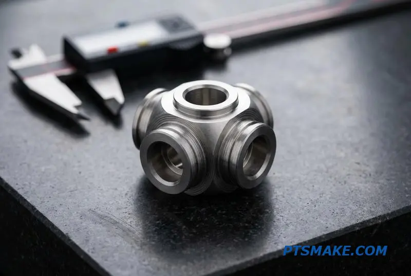
The CNC Valve Body Machining Workflow
A successful outcome starts with material selection. The choice depends entirely on the application’s demands for corrosion resistance, weight, and cost. We guide clients through these decisions to find the optimal balance for their projects.
| Material | Primary Benefit | Common Application |
|---|---|---|
| 316L Stainless Steel | Corrosion Resistance | Medical, Marine |
| 6061-T6 Aluminum | Lightweight | Aerospace |
| Brass | Cost-Effective | General Plumbing |
Multi-Axis Strategies in Action
For a component like a 3-way proportional valve body, we often start with 316L stainless hex bar on a mill-turn center. This allows us to machine the main bore and external features simultaneously, which is highly efficient. Cross-drilling the side ports requires precise multi-axis positioning.
One of the biggest challenges is evacuating chips from deep internal passages. Poor chip removal can damage the surface finish or break a tool. We use through-tool coolant and peck drilling cycles to flush chips out, but this can cause Work Hardening2 in materials like stainless steel.
Creating a pressure-containing valve body is a multi-stage process. It demands careful material selection, efficient multi-axis machining for complex internal geometries, and specific strategies to overcome challenges like internal chip evacuation. Success depends on controlling every variable from start to finish.
Spool and Sleeve Machining — Sub-Micron Clearance Defines Leakage Rate
In high-performance hydraulic systems, precision is everything. The spool and sleeve assembly is the heart of proportional and directional control valves. Its performance hinges on the clearance between these two components, a gap often measured in single-digit microns. This tiny space dictates everything.
The Sub-Micron Challenge
Achieving a clearance of just 3 to 8 microns is no simple task. It requires an advanced understanding of materials, heat treatment, and multi-stage machining processes. Any deviation directly impacts the valve’s efficiency and service life, making it a critical focus for us at PTSMAKE.
Key Performance Metrics
The relationship between spool-to-sleeve clearance and valve performance is direct and unforgiving. Tighter clearance improves control and reduces energy loss, while excessive clearance leads to failure. Below is a breakdown of how clearance affects key metrics.
| Performance Metric | Impact of Sub-Micron Clearance |
|---|---|
| Internal Leakage Rate | Lower clearance minimizes fluid bypass, boosting efficiency. |
| Pressure Gain | Tighter tolerance allows for sharper pressure response. |
| Valve Lifespan | Proper clearance with hard surfaces reduces wear. |
| System Responsiveness | Minimized leakage ensures rapid and predictable actuation. |
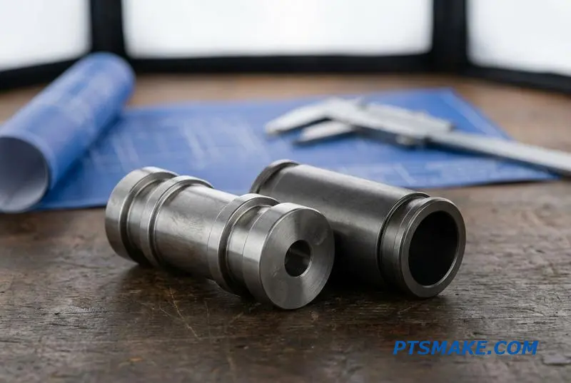
Achieving sub-micron precision in spool valve CNC machining requires a meticulously planned sequence of operations. Each step builds upon the last, where a single error can compromise the entire assembly. This isn’t just about hitting a final dimension; it’s about controlling geometry and surface finish throughout the process.
The Path to Precision
The journey from raw material to a finished component is complex. Based on our work with clients on components for systems including industrial hydraulics and Liquid Cooling Valves, we’ve refined a process that delivers consistent, high-precision results. It involves careful control at every stage.
Critical Machining Steps
First, we perform hard turning after heat treatment to establish the near-net shape. Then, external cylindrical grinding is used on the spool. We aim for a surface finish (Ra) of 0.1 μm or better and a Cylindricity3 within 2 μm to ensure a uniform seal.
The sleeve’s internal bore undergoes honing or precision boring to match. Finally, all metering notch edges are deburred to a specification of less than 0.01mm. This prevents flow disruption and ensures precise control. Surface treatments like nitriding or DLC coatings are applied for wear resistance.
Alternative Machining Processes
While grinding and honing are standard, alternative methods suit specific needs. EDM, for instance, is excellent for creating complex spool profiles or intricate metering notches that are difficult to machine conventionally.
| Process | Application | Advantage |
|---|---|---|
| Grinding/Honing | Standard spool & sleeve production | High precision, excellent surface finish |
| EDM | Complex spool metering notches | Intricate geometries, no tool pressure |
| Gun Drilling | Long, straight valve sleeves | High depth-to-diameter ratio bores |
Mastering spool and sleeve machining requires a holistic approach. The final sub-micron clearance is a direct result of a multi-stage process where every step, from heat treatment to final lapping, is critical for achieving optimal valve performance, efficiency, and lifespan.
Butterfly Valve Disc Machining — Large Diameter Thin-Wall Precision
Machining large butterfly valve discs for liquid cooling presents unique challenges. For pipe diameters from 50mm to over 200mm, the discs must be thin to minimize pressure drop. This thin-wall design makes them highly susceptible to warping from clamping forces and tool pressure during manufacturing.
The Balancing Act of Precision
Maintaining flatness is the primary goal. Even minor distortion can compromise the seal, leading to system failure. The key is precise control over every step, from material selection to the final finishing pass. This ensures the component meets strict operational requirements.
Material Selection Matters
The choice of material directly impacts both performance and manufacturability. Each option offers a different balance of corrosion resistance, weight, and cost.
| Material | Primary Advantage | Common Application |
|---|---|---|
| 316L Stainless Steel | Corrosion Resistance & Durability | Standard Liquid Cooling |
| Hastelloy C276 | Extreme Chemical Resistance | Aggressive Coolant Systems |
| Coated Aluminum | Lightweight | Rack-Level Cooling Valves |
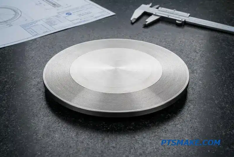
Advanced designs like double-offset and triple-offset discs are common in high-performance liquid cooling valves. These geometries require complex 5-axis CNC positioning to create precise sealing surfaces. At PTSMAKE, our process for butterfly valve disc CNC machining is carefully sequenced to manage these complexities and control part stability.
Our Machining Sequence
We start with face turning to establish a flat reference surface. Next, we use contour milling for the critical sealing edge. This is followed by drilling the stem holes with precise angular orientation, a step crucial for proper valve actuation. Throughout this process, managing Residual Stress4 is critical to prevent deformation. A final, light deburring pass ensures a perfect finish without introducing new stresses.
Sealing Edge Geometry
The sealing edge is not flat; it’s a spherical or conical surface. This geometry must mate perfectly with the valve’s seat liner to create a leak-proof seal. Achieving this requires specialized tooling and programming expertise, especially on materials like Hastelloy C276, which is notoriously difficult to machine. Our experience ensures we produce a flawless sealing surface every time.
Successful machining of large, thin-wall valve discs requires a blend of advanced 5-axis technology, a meticulous process sequence, and deep material knowledge. This ensures the final component is flat, precise, and ready for demanding liquid cooling applications.
Valve Seat and Seat Ring Machining — The Mating Surface That Cannot Leak
The valve seat is the stationary foundation of a reliable seal. In high-stakes applications like liquid cooling systems for electronics or machinery, this component’s performance is non-negotiable. A leak, no matter how small, can lead to system failure.
The Foundation of a Seal
This surface mates directly with the valve’s moving part, like a ball or a poppet, to stop flow. The precision of its machining dictates the effectiveness and longevity of the entire valve assembly. Even a minor imperfection can compromise the seal.
Key Sealing Surface Types
Different applications demand different materials and designs. Understanding the primary types is the first step in specifying the correct valve for your system.
| Seat Type | Material Composition | Common Application |
|---|---|---|
| Elastomeric | Polymer or Rubber Insert | General purpose, excellent sealing |
| Metal | Machined Metal Surface | High-temperature or aggressive fluids |
| Composite | Metal Ring with Bonded Elastomer | Combines durability with sealing |
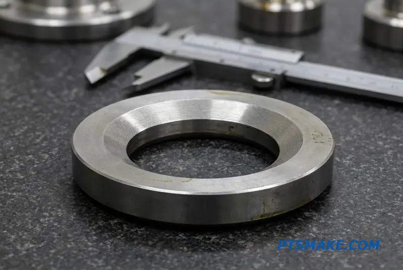
When dealing with metal seats, precision is everything. The valve seat CNC machining process must be controlled with extreme care, as there is no soft material to compensate for geometric errors. This is especially true in systems that cannot tolerate any leakage.
Precision Requirements for Metal Seats
For metal-to-metal seals in liquid cooling valves, we adhere to strict geometric and surface finish tolerances. After years of testing and collaboration with clients, we have found these specifications to be critical for achieving a perfect, repeatable seal under pressure.
| Machining Parameter | Tolerance Requirement | Impact on Performance |
|---|---|---|
| Conical Seat Angle | ±0.1 degree | Ensures full contact with the closing element |
| Surface Finish (Ra) | ≤ 0.2 μm | Minimizes potential leak paths |
| Concentricity5 | ≤ 0.025mm TIR | Prevents uneven sealing pressure |
Machining Strategy
To eliminate tolerance stack-up, we often press the rough-machined seat into the valve body first. Then, we perform the final finish machining of the seat in its assembled position. This ensures the sealing surface is perfectly aligned with the valve’s central axis.
A recent project involved a 316L valve seat for a 1-inch liquid cooling ball valve. We machined its 45-degree conical sealing surface to a total runout of less than 0.05mm, ensuring a flawless seal under high-pressure coolant circulation.
Achieving a leak-proof seal in liquid cooling valves depends entirely on the precision of valve seat CNC machining. Key factors include seat type, tight control over angle and surface finish, and maintaining exceptional concentricity between the seat and the valve bore.
Stem and Shaft Machining — Rotary-to-Linear Precision Transmission
Stems and shafts are the heart of a valve’s actuation system. They translate rotary or linear force from an actuator directly to the closure element. Without precision, this entire transmission fails, leading to leaks, inaccurate control, and premature wear. Their function is multi-faceted and demanding.
Key Functional Demands
The design must account for torque transmission, sealing, and positioning. Any compromise in one area directly impacts the valve’s overall performance and reliability. Proper valve stem CNC machining is essential to meet these requirements.
Sealing and Positioning
A critical function is sealing against the bonnet or stuffing box to prevent fluid leakage. The stem’s surface must be flawless. Simultaneously, it provides crucial positioning feedback to the control system, ensuring precise flow regulation.
| Component | Primary Motion | Key Machining Challenge |
|---|---|---|
| Stem | Linear (Up/Down) | Concentricity between threads and sealing surface |
| Shaft | Rotary (Turning) | Keyway or flat milling for actuator fit |
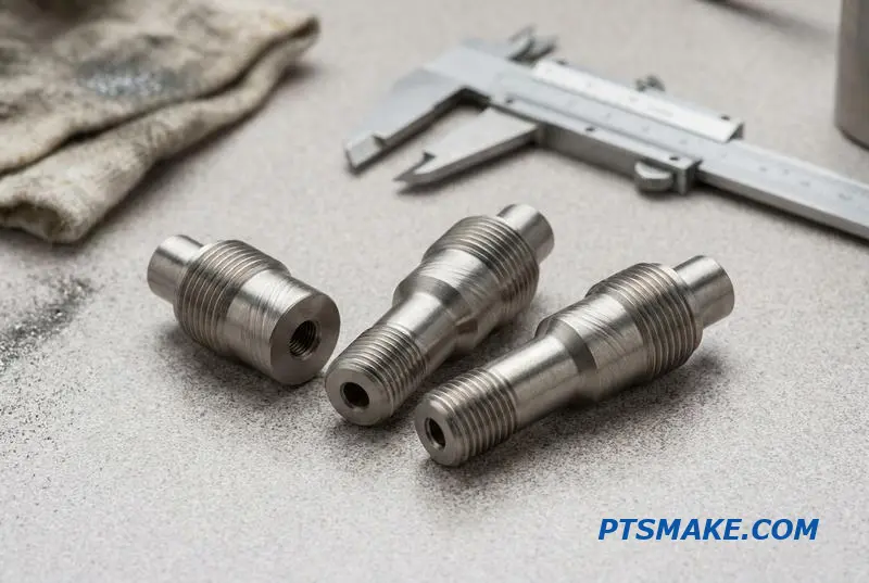
Achieving Precision in Stem and Shaft Machining
To ensure reliable valve operation, several machining requirements are non-negotiable. At PTSMAKE, we focus on these critical details to prevent common failure modes. The interaction between the stem and its housing is a primary focus for long-term performance.
Concentricity and Surface Finish
The concentricity between the threaded section and the sealing section must be exceptionally tight, often within 0.02mm. This prevents uneven pressure on seals. The stem’s surface finish in the packing seal area must be Ra ≤ 0.4 μm to avoid abrasion and ensure a leak-proof seal.
Threading Method Comparison
The method used for creating threads significantly impacts the stem’s durability. Rolled threads are superior to cut threads because the process cold-works the material, improving its grain structure and overall strength.
| Threading Method | Process Description | Key Advantage |
|---|---|---|
| Thread Rolling | Threads are formed by plastic deformation. | Superior fatigue strength6 and smoother finish. |
| Thread Cutting | Material is removed to create threads. | Suitable for small batches and custom profiles. |
Material Choices for Valve Stems
Material selection depends on the application’s demands for strength, corrosion resistance, and temperature tolerance. Choosing the wrong material can lead to catastrophic failure.
| Material | Key Properties | Common Application |
|---|---|---|
| 17-4PH Stainless | High strength, good corrosion resistance | General industrial, high-pressure systems |
| 316L Stainless | Excellent corrosion resistance, standard use | Chemical processing, food and beverage |
| A286 Alloy | High-temperature strength, corrosion resistant | Aerospace, high-temperature valves |
Precise stem and shaft machining is fundamental for valve performance. Key factors include achieving tight concentricity, a fine surface finish for sealing, and selecting the appropriate material. The threading method also significantly impacts the component’s fatigue life and overall reliability in demanding applications.
Solenoid Valve Armature and Core Tube Machining — Magnetic Circuit Precision
The performance of a solenoid valve hinges on two core components: the armature and the core tube. Their precise interaction creates the magnetic circuit that drives the valve. Machining these parts is a game of microns where precision directly impacts response time and reliability.
Material Selection is Critical
Choosing the right material is the first step. The material must balance magnetic properties with corrosion resistance. Our team often works with specific grades to meet diverse application demands.
| Material | Key Advantage | Machining Challenge |
|---|---|---|
| 430F Stainless Steel | Good magnetic properties | Gummy, prone to work-hardening |
| Pure Iron | Highest magnetic permeability | Requires protective plating |
| Soft Magnetic Alloys | Specialized performance | Often abrasive and tough |
The Importance of the Air Gap
The radial gap between the armature and core tube is non-negotiable. Even a slight deviation affects the magnetic force, leading to slow or failed actuation.
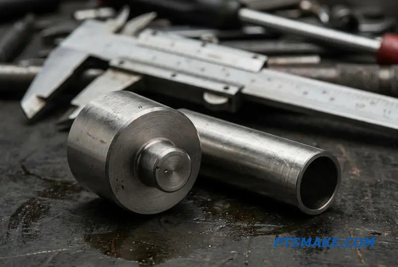
Successful solenoid valve CNC machining goes beyond just hitting dimensions; it’s about mastering the material’s behavior. Magnetic stainless steels like 430F are notoriously difficult. They are "gummy," meaning they can build up on the cutting tool, and they work-harden rapidly under pressure.
Overcoming Machining Hurdles
To counter this, we use sharp tooling with specific chip-breaking geometries. This approach prevents material buildup and ensures a clean cut without introducing stress. It is a process we have refined over many projects. The concentricity between the armature and core tube is paramount, as the air gap, often just 0.05-0.15mm, dictates solenoid force.
The Armature Guide Tube
Another critical part is the thin-walled armature guide tube. This component isolates the fluid from the coil. It requires exceptional concentricity between its inner and outer diameters. Maintaining its roundness during machining is a significant challenge. Precision here is vital for components used in demanding systems, from aerospace actuators to high-reliability liquid cooling valves. The effectiveness of the entire magnetic circuit depends on the magnetic permeability7 of the chosen materials.
Precision in material selection, gap control, and machining techniques is non-negotiable for solenoid valve components. These factors directly determine the valve’s response time, force, and long-term reliability in critical applications.
Pressure Relief Valve Components — Spring Retainer and Nozzle Machining
In liquid cooling systems, pressure relief valves are the final line of defense. Their reliability hinges on the precision of internal components. I focus on two key parts: the nozzle and the spring retainer. Proper machining of these elements is non-negotiable for consistent performance.
The Nozzle’s Critical Edge
The nozzle’s sharp-edged orifice is crucial. Any burr or radius affects the set pressure. We must maintain a precise edge condition to ensure the valve opens exactly when intended. This is a core aspect of manufacturing reliable pressure relief valve components.
Spring Retainer and Sealing Integrity
The spring retainer holds the spring, but its interaction with the poppet or disc is vital. The flatness and concentricity of these parts ensure a perfect seal. Below are the key machining tolerances we manage at PTSMAKE.
| Component | Critical Feature | Tolerance Requirement |
|---|---|---|
| Nozzle | Sealing Land Finish | Ra 0.2 μm or better |
| Nozzle | Cone Angle | ±0.5° |
| Poppet (Metal) | Sealing Face Flatness | ≤ 0.002mm |
| Poppet (Soft) | Sealing Face Flatness | ≤ 0.005mm |
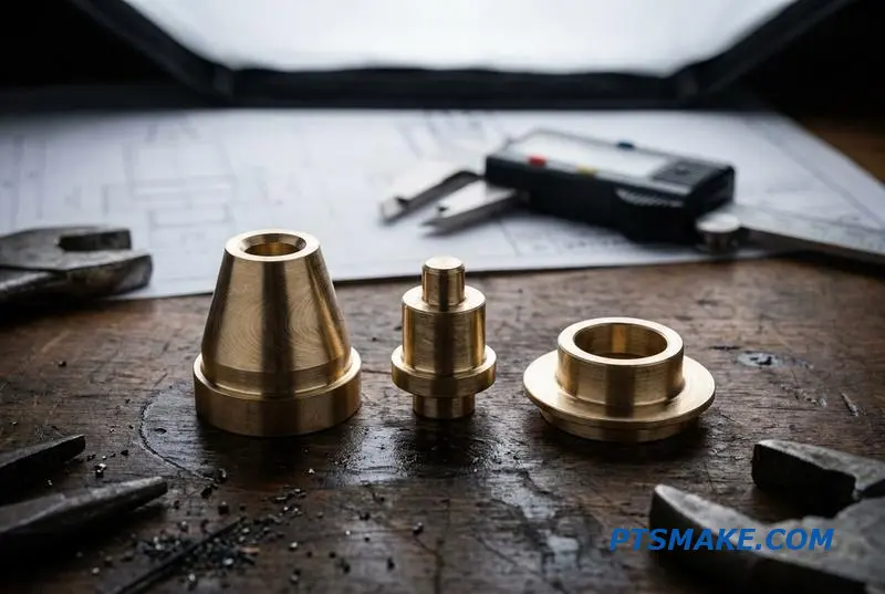
The link between machining and performance is direct. A tiny flaw, like a 0.02mm burr on the nozzle edge, can shift the cracking pressure by as much as 10%. This deviation is unacceptable in high-stakes applications where overpressure can cause catastrophic failures.
Machining for Repeatability
Achieving such precision in pressure relief valve components CNC machining requires tight process control. For the poppet, the guide diameter’s concentricity relative to the sealing face ensures it moves smoothly and seats correctly every time, preventing leaks and inconsistent reseating. This directly impacts the valve’s Hysteresis8.
Testing and Verification
After assembly, every valve undergoes bench testing to verify its set pressure. However, I always recommend in-situ pressure verification where possible. This confirms the valve performs as expected within the actual operating environment, accounting for factors like system dynamics and fluid temperature.
| Verification Method | Purpose | Best Application |
|---|---|---|
| Bench Testing | Initial QC, Set Pressure Verification | Post-assembly, batch validation |
| In-situ Verification | Real-world Performance Check | System integration, final commissioning |
This two-stage approach provides the highest level of assurance for critical Liquid Cooling Valves.
The reliability of a pressure relief valve is not determined by its design alone but by the micron-level precision of its core components. The nozzle’s edge condition and the poppet’s flatness are critical factors that directly influence safety and system integrity.
Check Valve Components — Ensuring Crack-Free One-Way Flow
In liquid cooling systems, preventing backflow is non-negotiable. Check valves act as one-way gates, and their reliability hinges on the precision of their components. The choice of valve type directly impacts performance and the complexity of the manufacturing process.
Common Liquid Cooling Valves
The most common types I work with are spring-loaded poppet, swing, and dual-plate check valves. Each has specific applications where it excels. For high-reliability systems, the spring-loaded poppet design often provides the most consistent performance due to its simple, direct mechanical action.
Valve Type Comparison
| Valve Type | Primary Application | Key Machining Challenge |
|---|---|---|
| Spring-Loaded Poppet | High-pressure, fast-response systems | Seat surface finish and concentricity |
| Swing Check | Low-pressure, large-diameter lines | Hinge mechanism precision |
| Dual-Plate | High-flow, space-constrained areas | Plate and spring alignment |
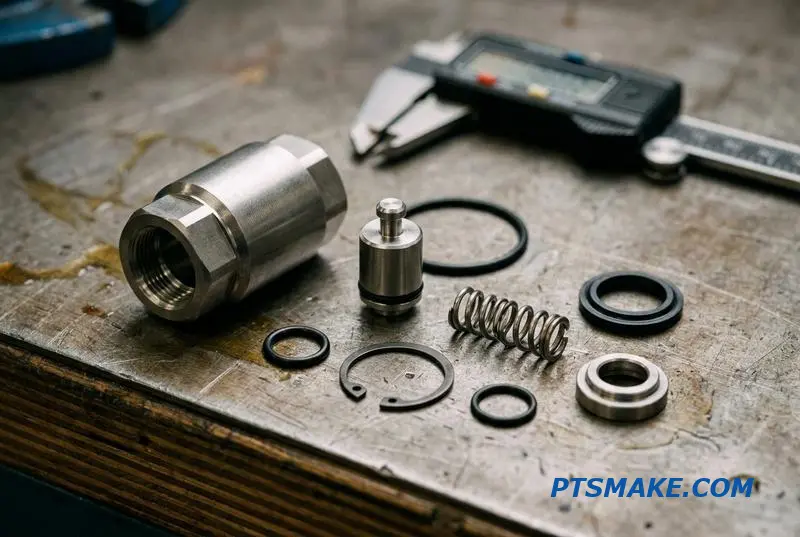
Precise check valve CNC machining is fundamental to achieving consistent performance, especially regarding cracking pressure. This is the minimum upstream pressure required to open the valve. Inconsistent cracking pressure across a batch of valves indicates underlying manufacturing tolerance issues that can compromise an entire system.
Key Machined Components
Four components demand the highest precision.
Body and Seat Insert
The conical sealing surface of the valve body or seat insert is critical. We machine this to a surface roughness of Ra ≤ 0.4 μm to ensure a perfect seal against the poppet or disc.
Poppet or Disc
The poppet must have a perfectly machined surface to match the seat. For soft seals, we create a precise O-ring groove. The depth and width of this groove are vital for correct O-ring compression.
Guide Stem and Spring Pocket
The guide stem ensures the poppet aligns with the body bore, a task requiring concentricity within 0.05mm. The spring pocket must have a smooth, flat bottom to prevent spring buckling under compression. This is where Tolerance stack-up9 analysis is crucial.
Tolerance Interaction Example
After analysis with a client, we determined how three tolerances interact to affect cracking pressure.
| Component Feature | Tolerance | Impact on Cracking Pressure |
|---|---|---|
| Body Seat Angle | ±0.5° | Affects initial sealing point |
| O-Ring Groove Depth | ±0.05 mm | Changes O-ring compression |
| Spring Free Length | ±0.10 mm | Varies initial spring force |
Ultimately, the reliability of a check valve in a liquid cooling system is determined by the precision of its machined parts. Controlling the tolerances of the body, poppet, and spring features ensures a consistent and reliable cracking pressure for every unit produced.
Bonnet and Cap Machining — Pressure Containment With Thread and Gasket Interfaces
In pressure systems, bonnets and caps are not just covers; they are critical pressure-containing components. Their primary job is to create a reliable, leak-proof seal. This seal is achieved through the precise machining of thread and gasket interfaces, which must work together perfectly.
Key Machining Interfaces
For components like Liquid Cooling Valves, the bonnet seals the valve body and guides the stem. The cap often closes an access port. Both rely on flawless machining to prevent leaks under pressure. Proper execution here is what separates a reliable system from a failure point.
Common Bonnet Types
Different applications require different bonnet designs. The choice depends on pressure, size, and the need for maintenance access.
| Bonnet Type | Typical Application | Sealing Method |
|---|---|---|
| Screwed | Low-pressure systems | Threads and sealant |
| Bolted | High-pressure, large valves | Gasket and bolt tension |
| Welded | Hermetically sealed loops | Permanent weld joint |
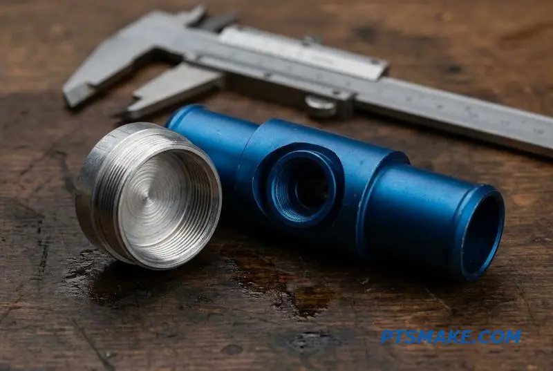
The success of a bonnet relies entirely on the precision of its machined features. For Liquid Cooling Valves, we often use thread turning or milling to create NPT or BSPP threads. A small groove for sealant is frequently machined alongside the threads to ensure a robust seal.
Gasket Face and Sealing Features
The gasket face is equally critical. Its flatness and surface finish determine the seal’s integrity. At PTSMAKE, we machine faces to a Ra ≤ 1.6 μm for spiral-wound gaskets and a finer Ra ≤ 0.8 μm for O-ring face seals. This level of control prevents micro-leaks.
Stem Bore and Anti-Rotation
The stem bore requires tight control over its diameter and depth to house the packing correctly. We also machine anti-rotation features like tabs or hex geometries. These features lock the bonnet to the valve body, preventing it from loosening due to vibration or operational stress.
Material Compatibility
Finally, material selection is key. The bonnet and body must be made from compatible materials to avoid galvanic corrosion10. This electrochemical reaction can quickly degrade mating surfaces, especially in liquid cooling systems, leading to catastrophic failure. Proper valve bonnet CNC machining considers this from the start.
Successful bonnet and cap machining ensures pressure containment by focusing on thread accuracy, gasket face finish, and material compatibility. These precision features work together to create a reliable, leak-proof seal, which is fundamental for system safety and performance.
Thread Standards for Liquid Cooling Valves — NPT, BSPP, BSPT, and SAE Ports
Selecting the right thread standard for liquid cooling valves is not a minor detail; it’s fundamental to system integrity. In high-stakes environments like data centers, a leak can be catastrophic. The choice between NPT, BSPP, BSPT, and SAE ports directly impacts sealing reliability and maintenance.
Key Thread Standards Overview
Each standard has a distinct sealing mechanism and is preferred in different regions or applications. Understanding these differences is the first step in designing a robust liquid cooling loop. The wrong choice can lead to persistent, hard-to-diagnose leaks.
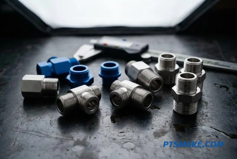
| Thread Standard | Sealing Method | Common Application | Key Characteristic |
|---|---|---|---|
| NPT | Tapered Threads (Interference Fit) | US Data Centers | Requires sealant (tape or paste) |
| BSPP (G) | Parallel Threads with Bonded Seal | Vibration-prone Systems | Relies on a gasket or O-ring |
| BSPT (R/Rp) | Tapered Threads | European Systems | Similar to NPT but different angle |
| SAE J1926 | Straight Thread with O-ring | High-Pressure Coolant Loops | Excellent sealing, reusable |
Precision Machining for Leak-Proof Connections
The thread standard itself is only half the story. How that thread is machined into the valve body is equally critical. At PTSMAKE, we focus on methods that ensure maximum sealing performance for our clients’ liquid cooling valves.
CNC Threading Methods
Thread milling is our preferred method for valve port threads, especially for NPT. It produces a superior thread form and surface finish, which is essential for the metal-to-metal seal. Unlike tapping, it creates perfect threads from the first to the last turn without lead-in marks. This precision is vital for consistent sealing.
Single-point thread turning works well for smaller diameters, but we limit passes to maintain thread integrity. Thread rolling is ideal for valve stems and bonnet threads, as it improves fatigue life by work-hardening the material, but it’s not suitable for internal port threads.
A Practical Example: NPT Sealing
Consider a manifold and valve both specifying NPT threads. A tapped valve port can have slight imperfections that compromise the seal. A thread-milled port, however, offers superior concentricity and surface finish, creating a more reliable interference fit that prevents leaks and resists thread galling11 during assembly.
Choosing the correct thread standard and machining process, like thread milling for NPT ports, is essential for creating leak-proof liquid cooling valves. This decision directly impacts system reliability and long-term performance, preventing costly downtime.
Cleanliness Requirements for CNC-Machined Cooling Valve Components
The performance of a liquid cooling system hinges on more than just dimensional accuracy. Internal cleanliness is a critical factor for CNC-machined cooling valve components. Neglecting this detail can lead to catastrophic system failures, a lesson I’ve seen firsthand in high-stakes applications.
The Hidden Risks of Contamination
Machining debris, burrs, or cutting fluid residue left inside a valve body are not minor issues. These contaminants can jam the valve’s spool or poppet, rendering it inoperable. They can also break free and circulate, contaminating the entire cooling loop and blocking sensitive microchannels.
Impact of Poor Valve Cleanliness Machining
| Contaminant Type | Potential Failure Mode | System-Level Impact |
|---|---|---|
| Metal Fines/Chips | Spool/Poppet Jamming | Complete loss of flow control |
| Burrs | Abrasion of Seals | Coolant leakage, pressure loss |
| Cutting Fluid Residue | Pump Damage | Reduced pump lifespan, system inefficiency |
| Particulates | Blocking Microchannels | Overheating of critical components |
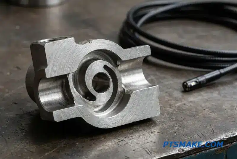
Achieving the required level of cleanliness demands a documented and repeatable process. A simple wash is insufficient for the complex internal passages found in modern liquid cooling valves. At PTSMAKE, we match the cleaning method to the component’s geometry and material for optimal results.
Advanced Cleaning Methodologies
For standard stainless steel or aluminum bodies, aqueous ultrasonic cleaning is highly effective. For parts with intricate internal channels, precision vapor degreasing offers superior penetration. High-pressure fluid flushing through the valve’s ports ensures that even the most stubborn particles are dislodged and removed from deep within the component.
Verification is Non-Negotiable
Cleaning without verification is just guesswork. We validate cleanliness using several methods. Particle counting per ISO 4406 is standard, with a target class of 18/16/13 often required for data center cooling systems. A borescope inspection provides visual confirmation for internal passages. These steps ensure that the part is not just machined correctly but is also fit for a clean system. This prevents issues like pump Cavitation12, a destructive phenomenon caused by vapor bubble collapse.
Internal cleanliness of liquid cooling valves is not optional. It requires specific cleaning processes like ultrasonic or vapor degreasing and must be verified through methods like particle counting and borescope inspection to prevent catastrophic system failures and ensure reliability.
Helium Leak Testing for Liquid Cooling Valves — Standards and Acceptance Criteria
When discussing a liquid cooling valve leak test, we focus on two failure points. The first is seat leakage, an internal issue where fluid bypasses the closed valve mechanism. The second is body or bonnet leakage, which is an external escape of fluid to the atmosphere.
Each leak type demands a specific testing method and has different acceptance criteria. For external leaks in critical data center applications, the tolerance is effectively zero. Understanding these distinctions is crucial for ensuring the long-term reliability and performance of the entire system.
Choosing the Right Test Method
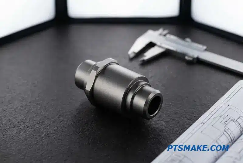
Not all leak tests are created equal. The method you choose depends entirely on the required sensitivity and production cycle time. For high-stakes components like liquid cooling valves, helium mass spectrometer testing is the gold standard for detecting minute external leaks, often down to 1×10⁻⁹ mbar·L/s.
For quick production checks, simpler methods are often sufficient. An air-under-water bubble test is a fast visual check for larger leaks. Pressure decay testing is ideal for automated, in-line verification of assembled valves, fitting within a 5-10 second cycle.
| Test Method | Typical Sensitivity (mbar·L/s) | Best Use Case |
|---|---|---|
| Helium Mass Spectrometer | < 1×10⁻⁶ | Final quality control, R&D validation |
| Air-Under-Water Bubble Test | ~ 1×10⁻³ | Quick, in-process production checks |
| Pressure Decay Test | ~ 1×10⁻⁴ | High-volume, automated assembly testing |
Acceptance Criteria and Machining Quality
Acceptance criteria are tied directly to the valve’s function. We often refer to ANSI/FCI 70-2 standards with our clients. For a critical shutoff valve, a Class VI "bubble-tight" seal is required. Proportional or control valves might only need to meet Class IV or V.
This is where machining quality is non-negotiable. Internal leakage rates are directly proportional to the surface finish and geometric tolerances of the valve spool and seat. The physics of fluid movement through these micro-gaps, often characterized by Laminar Flow13, means that even tiny imperfections can cause a failure.
Effective liquid cooling valve leak testing requires matching the method to the application. While external leakage has zero tolerance, internal seat leakage standards vary. Ultimately, superior machining precision is the foundation for meeting the strictest leakage criteria and ensuring long-term system integrity.
Material Selection for Machined Valve Components in Coolant Service
Choosing the right material for machined valve components in coolant service is not just about cost. It’s about ensuring long-term reliability and preventing catastrophic system failures. The interaction between the material and the coolant chemistry dictates the part’s lifespan.
Key Coolant Compatibility
Different coolants pose unique challenges. Deionized (DI) water is highly corrosive and demands robust alloys. Glycol mixtures are less aggressive but still require careful consideration, especially with metals like aluminum. Dielectric fluids, meanwhile, prioritize chemical compatibility with elastomers and seals.
Matching Material to Function
Each component inside a valve has a specific job. The body needs structural integrity, the spool demands wear resistance, and the seals require chemical and thermal stability. A mismatched material in any of these areas can compromise the entire liquid cooling system.
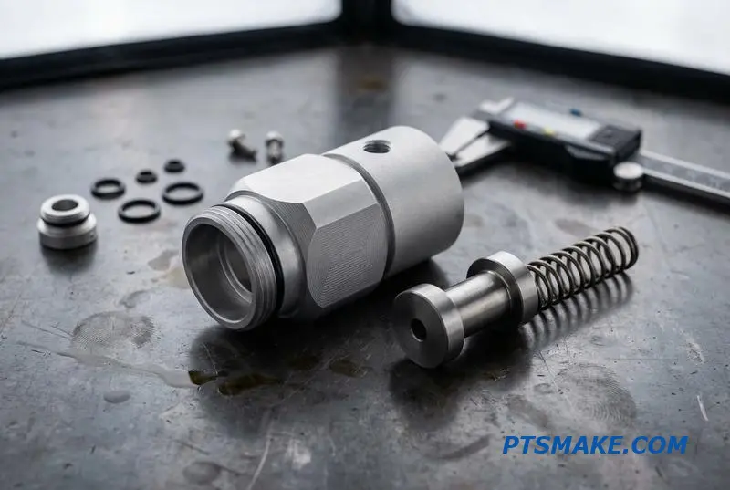
Proper valve material selection for coolant systems is a balancing act. You must consider the specific fluid, operating temperatures, and the mechanical stress on each individual part. A single oversight can lead to premature failure.
Component-Specific Material Breakdown
The valve body, for instance, is often machined from 316L stainless steel for broad compatibility or 6061-T6 aluminum for less corrosive environments. For spools requiring high wear resistance, I often turn to 17-4PH H900 stainless steel. In high-purity DI water systems, improper material choice can lead to issues like Pitting corrosion14, which can cause leaks.
Below is a quick guide we use at PTSMAKE for initial selections.
| Component | Recommended Material | Key Consideration |
|---|---|---|
| Body | 316L Stainless / 6061-T6 | Corrosion resistance vs. weight |
| Spool | 17-4PH H900 / 440C | Wear resistance and hardness |
| Seals | FKM / EPDM / PEEK | Chemical and temperature stability |
| Spring | Inconel X-750 / 302 SS | Fatigue and corrosion resistance |
| Fasteners | 316L Stainless / A286 | Strength and coolant compatibility |
Impact of Operating Temperature
We also account for temperature ranges. While return coolant is often 45-60°C, temperatures near the heat source can reach 70°C. Furthermore, steam-cleaning cycles can expose components to 120°C, which places extreme demand on elastomers like FKM.
Effective material selection requires balancing coolant chemistry, temperature, and component function. This holistic approach ensures the reliability and longevity of liquid cooling valves, preventing costly system downtime and maintenance. A material that excels in one area may fail in another.
Surface Treatments for Liquid Cooling Valve Components — Coating and Plating Guide
The performance of CNC-machined components in liquid cooling valves often hinges on their surface properties. Simply machining a part to tight tolerances is not enough. The right surface treatment is crucial for reliability and extending the component’s service life, especially under demanding conditions.
Why Surface Finishes Matter
Selecting the appropriate valve surface treatment for CNC parts prevents common failure modes. Key objectives include reducing friction between moving parts like a spool and sleeve, preventing galling in stainless-to-stainless contact, and improving resistance against both wear and aggressive coolants.
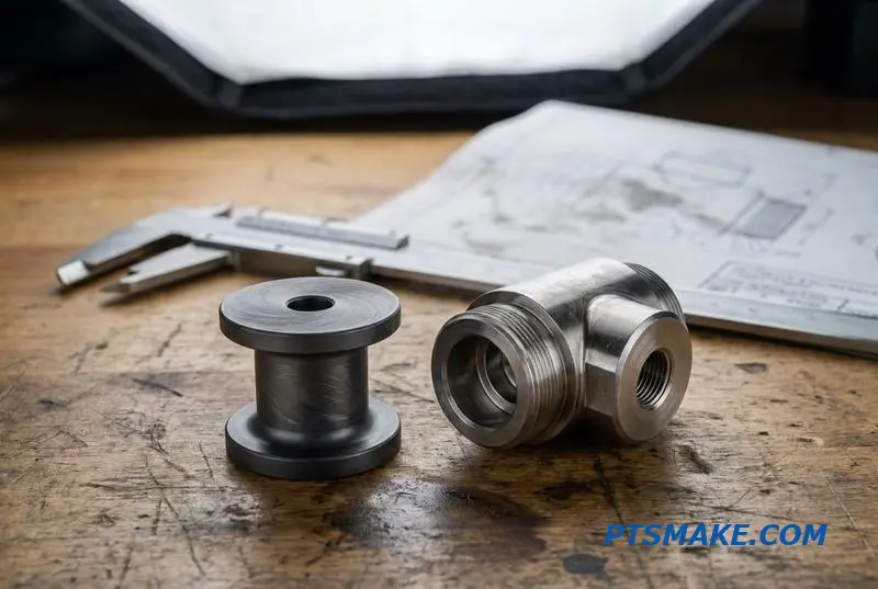
Choosing the right treatment requires balancing performance, cost, and manufacturability. At PTSMAKE, we guide clients through these trade-offs to ensure the final component meets system-level requirements. Let’s break down the most common options we work with for liquid cooling valves.
Common Coating and Plating Options
Electroless Nickel (EN) Plating: This is a go-to for valve internals. Its key benefit is providing a completely uniform coating, even on complex internal passages. It typically achieves a hardness of 48-55 HRC, offering excellent wear and corrosion resistance.
Diamond-Like Carbon (DLC) Coating: For applications requiring the lowest possible friction, DLC is unmatched. With a coefficient of friction around 0.1, it’s ideal for dynamic components like spools. However, its application is often limited to smaller parts due to process constraints.
Other Specialized Treatments: For 316L stainless steel valve bodies, we apply Passivation15 to remove free iron from the surface. This simple step significantly enhances the material’s natural corrosion resistance without altering its dimensions. PVD coatings like TiN are reserved for high-temperature applications.
Comparison of Valve Surface Treatments
| Coating Type | Hardness (HRC) | Friction Coefficient | Max Temp (°C) | Relative Cost | Recommended Application |
|---|---|---|---|---|---|
| Electroless Nickel | 48-55 | ~0.45 | ~400 | Medium | Valve internals, complex geometries |
| Hard Chrome | 68-72 | ~0.20 | ~500 | Medium-High | High-wear surfaces, piston rods |
| DLC | >80 | ~0.10 | ~350 | High | Spools, low-friction moving parts |
| PVD (TiN) | ~85 | ~0.40 | ~600 | High | Metal-seated valves, high-temp use |
| Passivation | N/A | N/A | N/A | Low | Stainless steel bodies (316L) |
Selecting the correct valve surface treatment for CNC components is a critical design decision. It directly impacts the reliability, efficiency, and lifespan of liquid cooling systems by addressing friction, wear, and corrosion.
Valve Prototyping for Liquid Cooling Systems — From CNC First Article to Production Ramp
Developing custom liquid cooling valves requires a structured path from concept to production. The goal is to validate your design quickly and cost-effectively. At PTSMAKE, we guide clients through a clear prototyping process that minimizes risk and accelerates time-to-market for critical thermal management components.
Step 1: CNC Billet Machining
The first step is creating initial physical parts. We machine 1-5 units directly from a solid billet of your chosen material. This typically takes 2-3 weeks and includes a full material certificate and First Article Inspection (FAI) report to verify every dimension.
Step 2: Design Validation
With parts in hand, you can begin testing. This phase is crucial for performance verification.
| Test Type | Purpose |
|---|---|
| Flow Testing | Verifies flow rate and pressure drop against specifications on a test bench. |
| Pressure Cycle Testing | Assesses long-term durability under operational pressure fluctuations. |
| Leak Testing | Confirms seal integrity using methods like helium or pressure decay. |
Step 3: Iteration
Testing reveals areas for improvement. Based on data, we can quickly revise the design. This may involve modifying metering notches for better flow control, adjusting port sizes, or changing seal materials to improve compatibility or prevent leaks. The agility of CNC machining is key here.
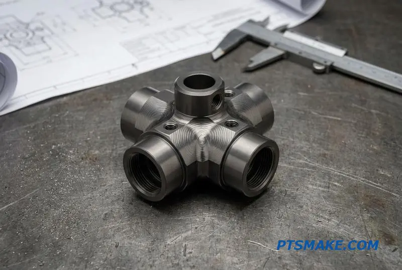
The prototyping path for liquid cooling valves often raises questions about cost, especially when comparing CNC machining to casting. For many applications, particularly in AI server or specialized electronics cooling, the volumes make fully CNC-machined valves the more economical choice over the product’s life.
The CNC vs. Casting Breakeven Analysis
CNC machining has zero tooling cost, unlike casting, which requires patterns that can cost thousands. We’ve seen clients save significantly on initial investment. A complex 3-way valve body on a 5-axis mill-turn might take 8-12 hours per part, resulting in a higher per-unit cost initially.
However, the breakeven point where casting becomes cheaper is often between 500 to 2,000 units. Many custom liquid cooling systems have annual volumes of 500 to 5,000 units. In this range, CNC machining remains highly competitive, avoiding large upfront tooling costs and allowing for design changes without penalty. Understanding the principles of Fluid Dynamics16 is essential for optimizing these designs from the start.
| Method | Tooling Cost | Per-Unit Cost (Low Volume) | Ideal Volume |
|---|---|---|---|
| CNC Machining | None | Higher | 1 – 5,000+ |
| Casting | High ($3k – $8k+) | Lower | 2,000+ |
This makes CNC valve prototyping and subsequent production a direct and financially sound strategy.
This structured CNC valve prototyping process validates design performance and provides a clear financial advantage for low-to-mid-volume production. It eliminates tooling costs and offers flexibility for design iterations, making it ideal for specialized liquid cooling valve applications.

Understanding this concept helps specify valve performance for optimal thermal management in complex systems. ↩
Understanding this effect is crucial for optimizing tool life and surface finish in stainless steel machining. ↩
Discover how this geometric tolerance impacts fluid dynamics and component lifespan. ↩
Understanding this concept is key to preventing deformation in high-precision, thin-walled components. ↩
Understanding this tolerance is key to designing parts for high-performance sealing applications. ↩
Learn how this property determines component endurance under cyclic loading. ↩
Explore how this property directly influences solenoid force and efficiency in electromagnetic designs. ↩
Understanding this helps in designing more reliable and predictable pressure regulation systems. ↩
This analysis helps predict assembly fit and function, which is critical for designing reliable mechanical systems. ↩
Understanding this electrochemical process helps in selecting compatible metals to prevent premature component failure. ↩
Understand this failure mode to improve the assembly and reliability of your high-performance threaded connections. ↩
Understanding this concept is key to preventing premature pump failure and maintaining system efficiency. ↩
Understanding this flow principle helps clarify how leak rate standards are established and why helium is an effective medium. ↩
Understanding this localized corrosion helps prevent unexpected failures in high-purity fluid systems. ↩
Learn how this process enhances the natural anti-corrosion properties inherent in stainless steel alloys. ↩
Explore the core principles of how fluids behave, which is critical for optimizing valve performance and efficiency. ↩