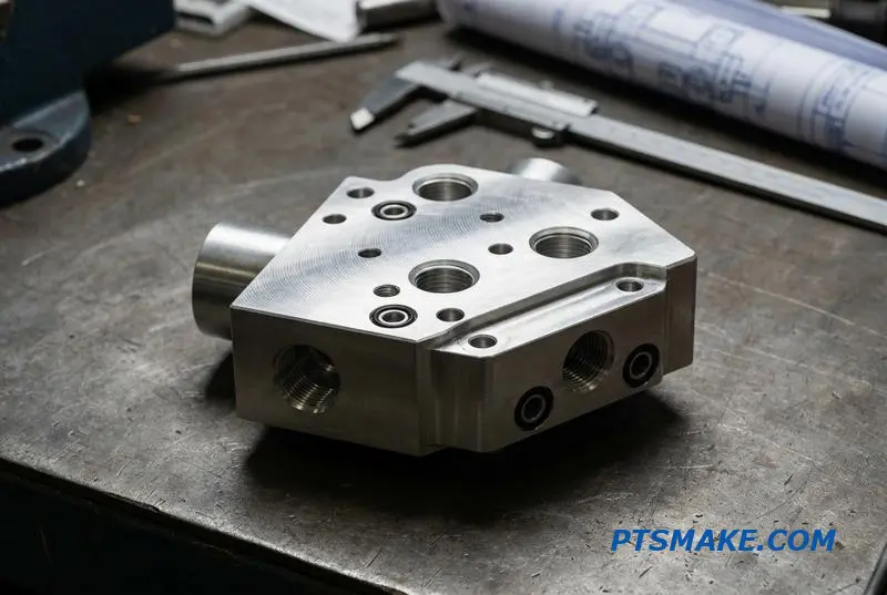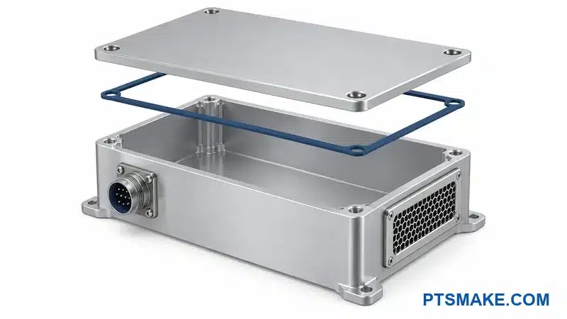

Buying an off-the-shelf harmonic actuator forces you to bend your arm geometry around a fixed housing. Embedded sensors won’t fit, sealing options are limited, and your joint design loses the precision edge that defines a competitive humanoid robot.
A CNC machined harmonic drive housing gives you full control over bore tolerances (H6/H7), bearing seats, seal interfaces, and mounting geometry. This is essential when you need custom arm integration, embedded torque sensing, IP54 sealing, or tight 0.025mm pilot fits for circular splines.
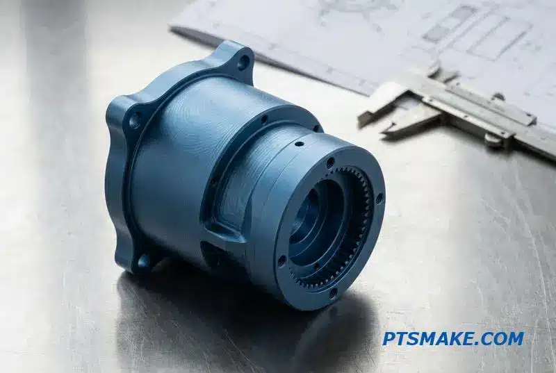
I’ve worked with robotics teams who lost months chasing torque ripple, only to find the root cause was a loose circular spline pilot fit. Below, I’ll walk you through every decision that shapes a reliable harmonic housing build.
When Should You CNC a Custom Harmonic Drive Housing Instead of Buying an Off-the-Shelf Actuator
When you have a harmonic drive component set, the primary decision is whether to buy a complete actuator or machine a custom housing. This choice directly impacts your project’s integration, performance, and timeline. It’s a common crossroads for teams developing advanced robotics.
Off-the-Shelf Actuators
An off-the-shelf unit offers a quick, validated solution. However, you are limited by its fixed dimensions, predefined sensor options, and standard mounting interfaces. This can create design compromises if your robotic arm link has a unique geometry or specific integration requirements.
Custom CNC Machined Housings
Opting for a custom CNC machined housing gives you complete design freedom. You control every interface, from motor mounts to output flanges. This path is ideal when standard units just don’t fit.
| Feature | Off-the-Shelf Actuator | Custom CNC Housing |
|---|---|---|
| Integration | Standardized, fixed interfaces | Fully customized to your design |
| Sensors | Limited, pre-integrated options | Unlimited placement and type |
| Geometry | Constrained by manufacturer | Matches your exact requirements |
| Lead Time | Shorter (if in stock) | Longer (design + manufacturing) |
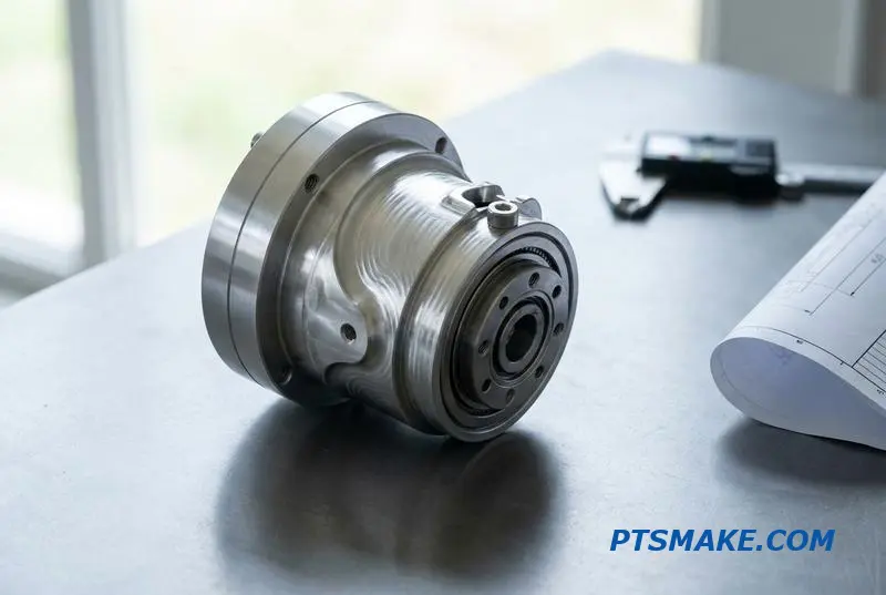
The decision to machine custom Harmonic Drive Housings becomes clearer when specific needs arise. If your design requires non-standard arm integration, an off-the-shelf actuator can force unwanted compromises on your entire mechanical structure. We often see this in compact humanoid or quadruped robot joints.
The Case for Customization
A custom housing allows you to integrate components like torque sensors directly into the structure for better accuracy and a cleaner assembly. Special sealing for harsh environments—like IP67 for outdoor robotics—is also far easier to achieve with a purpose-built housing. The design process adds overhead, but it eliminates integration headaches later.
Evaluating the Trade-offs
The core trade-off is between upfront development effort and long-term performance. While a standard actuator gets you moving faster, a custom solution ensures the final product meets exact specifications without compromise. This is critical for applications where weight, size, and Hysteresis1 are tightly controlled. We’ve found, working with our clients, that this initial investment in design pays off in performance.
| Decision Driver | Recommended Path | Rationale |
|---|---|---|
| Standard Footprint | Off-the-Shelf | Fast and proven for general use. |
| Unique Geometry | Custom CNC | Ensures perfect fit and optimal integration. |
| Embedded Sensors | Custom CNC | Allows for specific sensor placement and type. |
| Harsh Environment | Custom CNC | Enables tailored sealing and material choices. |
Choosing between off-the-shelf and custom is a strategic decision. Standard actuators prioritize speed for common applications, while custom CNC Harmonic Drive Housings offer complete control for projects with unique integration, sensor, or sealing requirements, ensuring optimal performance without compromise.
Circular Spline Pilot Fit — Why the 0.025mm Tolerance on This Bore Makes or Breaks Your Harmonic Drive
The performance of a precision harmonic drive hinges on the housing it sits in. Specifically, the pilot bore for the circular spline must be perfect. A deviation as small as 0.025mm can ruin the entire assembly. This single feature determines whether your expensive component operates smoothly or fails prematurely.
The Problem with Incorrect Fits
An incorrect bore tolerance creates two distinct failure modes. If the fit is too tight, it deforms the circular spline. If it’s too loose, the spline shifts under load. Both outcomes degrade performance significantly, turning a high-precision system into an unreliable one.
Fit Comparison
| Fit Condition | Consequence | Resulting Issue |
|---|---|---|
| Too Tight (Interference) | Deforms circular spline | Uneven tooth engagement, binding |
| Too Loose (Clearance) | Spline shifts off-center | Eccentricity, vibration, fatigue |
This isn’t a minor detail. A poorly machined housing can make a $400 harmonic drive perform worse than a standard $40 gearbox.
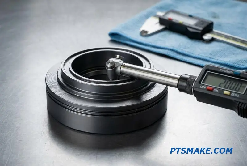
The pilot fit is where theory meets reality. The circular spline must be located centrally and securely. The standard ISO fits used here are typically H6 or H7. These are clearance fits, but with extremely tight control, ensuring the component is constrained without being deformed.
H6 vs. H7 Tolerance
For a 70mm circular spline, an H7 bore tolerance is +0.030mm / +0.000mm. An H6 fit is even tighter at +0.019mm / +0.000mm. A looser fit can introduce eccentricity, causing a once-per-revolution vibration known as torque ripple2. This vibration not only reduces positional accuracy but also accelerates flexspline fatigue, leading to early failure. The precision of Harmonic Drive Housings is not optional.
Verifying the Bore
You can’t just assume the bore is correct. At PTSMAKE, we verify every critical bore to prevent spline bore eccentricity failure. This simple quality check is crucial.
| Step | Action | Purpose |
|---|---|---|
| 1. Tool | Use a calibrated three-point bore gauge. | Ensures accurate and repeatable measurements. |
| 2. Depths | Measure at the top, middle, and bottom of the bore. | Checks for taper or barreling. |
| 3. Positions | Measure at four points (0, 90, 180, 270 degrees). | Detects out-of-roundness (ovality). |
| 4. Report | Document the average diameter and out-of-roundness. | Provides a complete record for quality assurance. |
This CNC housing bore verification ensures the housing meets the strict requirements for optimal harmonic drive performance.
The housing bore isn’t just a mounting feature; it’s a critical functional surface. Achieving the required H6 or H7 tolerance is essential for the harmonic drive’s accuracy, smoothness, and lifespan. Proper machining and verification are non-negotiable for these high-performance applications.
Cross-Roller Bearing Selection and Seat Machining — What Output Bearing Your Housing Must Fit
The performance of harmonic drive housings hinges on the output bearing. Cross-roller bearings are the standard choice because they manage combined loads within a compact space. The most critical step is selecting this bearing before you finalize the housing design. Its dimensions dictate your machining parameters.
Why Bearing Selection Comes First
The bearing’s outer diameter (OD) and width define the housing’s bore size and depth. If you design the housing first, you risk being unable to find a standard bearing that fits, forcing costly redesigns or custom bearing orders. This is a common and expensive mistake.
Common Bearing and Drive Pairings
A clear relationship exists between harmonic drive sizes and standard cross-roller bearing models. This makes initial selection straightforward if you know your drive requirements.
| Harmonic Drive Size | Typical Cross-Roller Bearing |
|---|---|
| 17 | RB6013 |
| 20 | RB7013 |
| 25 | RB8016 |
| 32 | RB10016 |
This table provides a starting point for matching components before any machining begins.
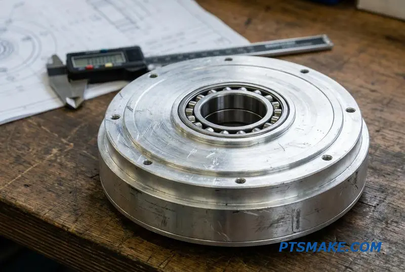
For harmonic drive housings, cross-roller bearings from brands like THK, IKO, or NSK are common. A typical choice for a size 20 drive is the RB7013 model, which has a 70mm bore and 13mm width. This directly informs the machining for the output bearing seat design.
Machining the Housing Bore
Achieving the correct fit is non-negotiable for performance. The housing bore that receives the bearing’s outer ring typically requires an H6 or H7 tolerance. This tight fit ensures the bearing is securely seated and prevents rotation. At PTSMAKE, we consistently hold these precise tolerances.
Shoulder and Shaft Tolerances
The shoulder depth tolerance is equally critical, usually held to ±0.01mm. This dimension sets the bearing’s axial position and controls preload. The inner ring, which fits onto the output flange or shaft, requires a g6 or h6 fit to match the bearing’s inner diameter (ID). The complex interplay of forces within the bearing, especially under load, creates significant Hertzian contact stress3 between the rollers and raceways. Incorrect fits will cause uneven stress distribution, leading to premature failure. My advice is simple: order the harmonic drive component set and the bearing together. Then, design the housing around these physical parts.
To ensure performance in harmonic drive housings, you must select the bearing and component set first. Then, design and machine the housing to the precise dimensions and tolerances required by those components. This proactive approach prevents costly errors and ensures optimal functionality.
The Biggest Cost Driver in a Harmonic Housing — Machine Time on the Critical Bore Set
When designing Harmonic Drive Housings, many engineers focus on material selection. They assume exotic alloys drive up the price. However, the raw material, often 7075 aluminum, is a minor part of the total cost. The real cost driver is machine time.
The True Cost Breakdown
The bulk of the expense comes from the hours a part spends on a high-precision CNC machine. For a typical housing, the machining can take several hours. The most time-consuming and expensive operation is creating the critical bore set.
Cost Distribution Example
Here is a simplified CNC harmonic housing cost breakdown we often see at PTSMAKE. This shows where the money really goes.
| Cost Component | Percentage of Total Cost |
|---|---|
| Raw Material (7075 Billet) | ~5% |
| CNC Machine Time | ~75% |
| Setup, Tooling & QA | ~20% |
As you can see, machine time dominates the cost structure. Understanding what happens during this time is key to effective cost management.
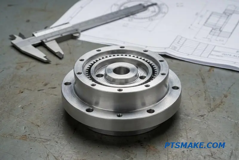
Inside the Machining Process
Why does the critical bore set consume so much time? It’s all about precision. The set includes the circular spline bore, the main bearing bore, and the motor mounting bore. These features must be perfectly concentric to ensure the harmonic drive functions correctly.
The Multi-Step Boring Sequence
Achieving H6 tolerance and tight concentricity (often 0.01mm) is a delicate process. It’s not just one quick cut. The sequence involves multiple careful steps to manage heat, tool deflection, and surface finish, preventing any distortion in the final part.
This multi-pass strategy is essential for achieving dimensional stability. The thermal equilibrium4 pause is especially critical. It allows the part to cool and stabilize before the final, high-precision cuts are made. This prevents inaccuracies caused by heat expansion during machining.
How to Reduce CNC Harmonic Housing Cost
Based on projects we’ve handled, there are several ways to reduce costs without sacrificing performance where it matters most.
| Cost Reduction Strategy | Potential Time Saving | Impact on Performance |
|---|---|---|
| Relax concentricity to 0.02mm | 15-20% of bore cycle time | Acceptable for many applications |
| Use H7 instead of H6 tolerance | 10-15% of bore cycle time | Looser fit on circular spline |
| As-machined non-critical faces | 5-10% of total machine time | Purely cosmetic, no functional change |
These small adjustments in your design can lead to significant savings. It’s a conversation worth having with your manufacturing partner.
The biggest cost in a harmonic housing isn’t the material, but the machine time for the critical bore set. By understanding this precision boring cost driver, you can make informed design choices that significantly reduce costs while maintaining the required performance for your application.
Aluminum 7075 vs 6061 for Harmonic Housings — When the Extra Cost of 7075 Actually Pays Off
Choosing the right aluminum for harmonic drive housings often comes down to 7075 versus 6061. While 6061 is a reliable workhorse, the higher cost of 7075 can be a tough sell. However, in specific applications, that premium is not just an expense; it’s a strategic investment in performance.
The Strength-to-Weight Advantage
For robotic joints, especially in humanoid designs, performance is paramount. The debate isn’t just about material cost but about what that cost buys you. Higher strength allows for thinner walls and lighter parts without sacrificing stiffness, directly impacting the robot’s dynamic capabilities and efficiency. This is where 7075 aluminum truly shines.
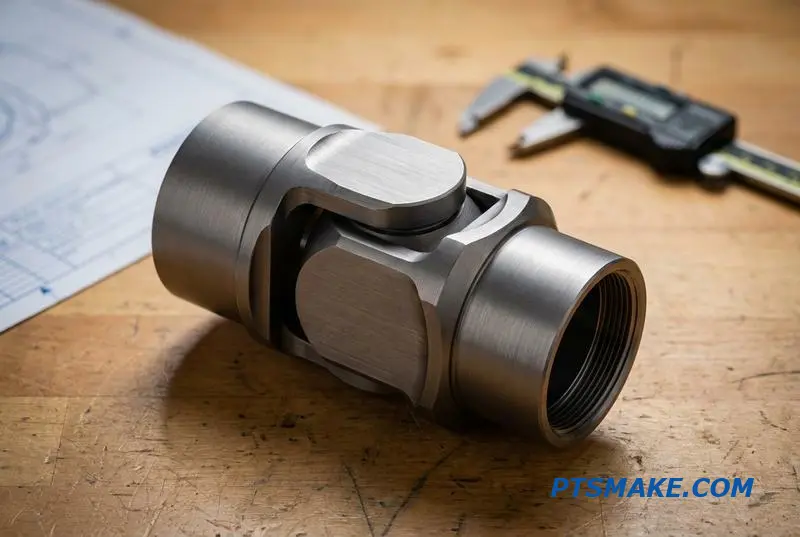
The decision between these two alloys hinges on a clear-eyed assessment of application requirements versus budget. The material cost for 7075 is roughly two to three times that of 6061. At PTSMAKE, our machining data confirms it’s also harder on tooling, increasing wear by about 30%. So, when does this investment pay off?
Key Performance Metrics Compared
Let’s look at the numbers. While both materials have nearly identical density and stiffness, the difference in strength is significant. This is the primary reason for selecting 7075 for demanding harmonic drive housings. The Young’s Modulus5 is the same, meaning a part of the same geometry will deflect identically under load.
| Property | Aluminum 7075-T6 | Aluminum 6061-T6 |
|---|---|---|
| Yield Strength | 503 MPa | 276 MPa |
| Stiffness (Young’s Modulus) | ~72 GPa | ~69 GPa |
| Density | 2.81 g/cm³ | 2.70 g/cm³ |
| Machinability | Fair | Good |
| Relative Material Cost | 2.5x – 3x | 1x |
When to Specify 7075
- Distal Joints: For wrists and end-effectors, every gram counts. The higher strength of 7075 allows for thinner walls, potentially cutting weight by 15-25% over a 6061 design. This reduces inertia, allowing for faster and more precise movements.
- High-Load Joints: Joints like hips or knees that handle high dynamic loads benefit from 7075’s superior strength, ensuring reliability under stress.
- Space-Constrained Designs: When packaging is tight and housing walls must be thin, 7075 provides the necessary strength that 6061 cannot.
When 6061 is Sufficient
- Prototyping: For early-stage iterations where validating geometry is more critical than final performance, 6061 is the cost-effective choice.
- Less Critical Joints: Shoulder joints, which often have more packaging space, may not require the premium strength of 7075.
- Reinforced Housings: If the design includes external brackets or supports that share the load, the inherent strength of the housing material becomes less critical.
Ultimately, the choice for your harmonic drive housings depends on the specific application’s demands. While 7075 commands a premium in both material and machining costs, its superior strength-to-weight ratio is indispensable for high-performance, weight-sensitive robotic joints.
Why Some CNC Shops Get Harmonic Housings Wrong — Six Common Failures and How to Catch Them
Harmonic Drive Housings are among the most demanding parts we machine. Their precision is non-negotiable, as even a tiny flaw can cause vibration, backlash, or complete failure in a robotic arm. Yet, many CNC shops miss the subtle details that define a perfect housing.
The Precision Trap
The challenge lies in maintaining tight tolerances across multiple features. Shops often focus on the main bore diameter but overlook how features interact. This leads to common harmonic housing failure modes that are difficult to detect without the right inspection methods.
A Buyer’s Inspection Guide
As a buyer, you need a simple but effective checklist. Understanding these six common failures and how to catch them will save you from costly line-down situations and field failures.
| Failure Mode | Primary Impact | Inspection Method |
|---|---|---|
| Bore Taper | Uneven spline contact | Bore Gauge |
| Out-of-Roundness | Poor bearing seating | CMM |
| Hole Position Walk | Flange misalignment | CMM |
| Thread Burrs | Incomplete bolt seating | Thread Gauge |
| Rough Seal Bore | Premature seal leak | Profilometer |
| Face Parallelism | Uneven load on bolts | Dial Indicator |
Successfully machining Harmonic Drive Housings requires a deep understanding of potential geometric and surface flaws. As a buyer, you must know what to look for during incoming inspection. Here are the most critical failure modes I’ve seen and how to identify them.
Geometric and Positional Errors
These errors relate to the shape and location of key features. They often result from improper setup, tool wear, or fixture instability. A common issue is a threaded hole position walk, where bolt holes deviate from their true position, preventing proper assembly.
Bore Taper
A tapered bore, often caused by tool deflection, prevents the circular spline from seating correctly. I recommend using a bore gauge to check the diameter at the top, middle, and bottom. If the taper exceeds 0.01mm, the part should be rejected.
Bearing Groove Out-of-Roundness
The groove for the cross-roller bearing must be perfectly round. Any deviation prevents the bearing from seating fully, leading to premature wear. A CMM is essential for this check; a roundness measurement exceeding 0.005mm is a clear sign of a bearing bore roundness failure.
Surface and Feature Flaws
These defects affect sealing, fastening, and overall component life. They are often process-related and can be avoided with careful programming and in-process checks. A thorough inspection can prevent major issues down the line.
| Failure | Inspection Tool | Acceptance Criteria |
|---|---|---|
| Threaded Hole Position | CMM | Check true position report |
| Burrs at Thread Entrance | Thread Gauge | Smooth entry, no snags |
| Seal Bore Roughness | Profilometer6 | Ra < 0.8μm |
| Housing Face Parallelism | Surface Plate & Dial Indicator | Check for flatness |
A classic seal surface roughness failure occurs when the bore is too rough, causing the lip seal to leak after only a few hundred cycles. This is a critical check for long-term reliability.
Inspecting Harmonic Drive Housings requires a systematic approach. By verifying bore geometry, feature positions, and surface finishes, you can effectively catch common manufacturing defects. This ensures the parts you receive will perform reliably and prevent costly system failures down the line.
Surface Finish on the Housing — Where You Need It Tight and Where You Can Save Money
Specifying surface finish is one of the most significant cost drivers in CNC machining. For components like Harmonic Drive Housings, getting this wrong can inflate your budget without adding any real performance benefit. The key is knowing exactly where a tight finish is critical and where you can relax requirements.
Critical vs. Non-Critical Surfaces
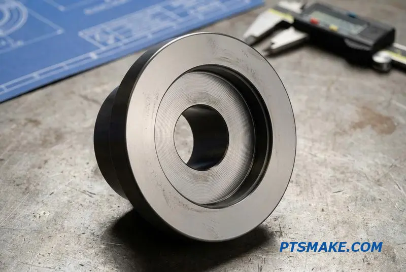
Not all surfaces are created equal. Mating faces, bearing bores, and seal contact areas need precise control. In contrast, internal pockets or external non-cosmetic faces don’t require the same level of finishing, and treating them as such is a common and costly mistake.
Surface Finish Application Guide
A smart approach to CNC surface finish cost savings involves a clear specification map for the part. Here is a typical breakdown for a robot housing.
| Feature Area | Typical Ra Requirement | Rationale |
|---|---|---|
| Rotary Seal Contact | 0.2 – 0.4μm (N5) | Prevents leaks and premature seal wear |
| Bearing Bores | < 0.8μm (N6) | Ensures proper fit and prevents stress points |
| Mating Faces | 0.8 – 1.6μm (N6-N7) | Guarantees flat, stable contact |
| External Cosmetic Walls | < 1.6μm (N7) | Aesthetic appeal and feel |
| Internal Pockets | 3.2μm+ (As-machined) | No functional impact, major cost savings |
The Engineering and Cost Rationale
Over-specifying a surface finish doesn’t make a part better; it only makes it more expensive. Each step down in Ra (Roughness Average) value often requires an additional, slower machining pass or a separate finishing process like grinding or polishing. This adds significant cycle time and cost.
Impact on Sealing Surfaces
For a rotary lip seal, the surface finish spec is non-negotiable. A surface rougher than Ra 0.4μm will act like a file, abrading the seal lip and causing early failure. Microscopic asperities7 can also create tiny leak paths, compromising the entire assembly’s integrity.
Bearing Bore Requirements
The bearing bore Ra requirement is just as important. A rough bore can create high-pressure points, affecting the bearing’s clearance and lifespan. It can lead to improper seating, which introduces vibration and reduces the precision of the entire harmonic drive system.
Quantifying the Cost Difference
The cost penalty for over-specification is substantial. Based on our work with clients on robot housing surface finish guidelines, moving from a standard cosmetic finish to a precision seal finish on just one feature can increase the cost of that feature by 200-300%.
| Finish Specification (Ra) | Relative Machining Cost | Typical Process |
|---|---|---|
| 3.2μm (or higher) | 1x (Baseline) | Standard Milling/Turning |
| 1.6μm | 1.5x | Fine Milling/Turning Pass |
| 0.8μm | 2x | Very Fine Pass or Grinding |
| 0.4μm | 3x+ | Grinding, Honing, or Lapping |
Applying that tight Ra 0.4μm finish across an entire part, where it isn’t needed, could increase the total part cost by 20-30%. A practical rule is to only specify a tight surface finish where a surface directly contacts a seal, a bearing, or another precision-machined mating face.
Strategic surface finish calls on Harmonic Drive Housings are essential. Apply tight Ra values only on critical functional interfaces like seals and bearings to ensure performance. Relaxing specifications on non-critical areas is the most effective way to optimize manufacturability and control costs without compromise.
Deburring Internal Features — The Hidden Quality Check That Finds Bad CNC Shops
Skipped internal deburring is a leading cause of assembly failure, especially for components like harmonic drive housings. Tiny burrs left on internal thread entries can break off during assembly. These metal fragments then lodge between gear teeth, causing noise, friction, and eventual system failure.
A shop’s approach to internal features is a clear indicator of its quality standards. A meticulous shop views deburring as a critical finishing step, while a low-cost shop often skips it to save time, passing the risk on to you.
Deburring Approach Comparison
| Quality Factor | High-Quality Shop (e.g., PTSMAKE) | Low-Quality Shop |
|---|---|---|
| Process | Integrated, often automated deburring cycle | Manual, inconsistent, or skipped |
| Verification | Borescope inspection of all internal features | Visual check of external surfaces only |
| PO Adherence | Follows specific edge break callouts | Ignores or overlooks internal specs |
| Outcome | Reliable, long-lasting assembly | High risk of premature field failure |
This small detail has a massive impact on the final product’s reliability and lifespan. It’s a non-negotiable quality gate for us at PTSMAKE.
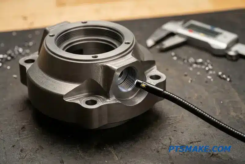
To avoid these issues, your purchase order must be explicit. We recommend specifying: ‘all edges broken 0.1-0.3mm max, internal thread entries machine-deburred, and all intersecting bore edges radiused R0.2 max.’ This language leaves no room for ambiguity. It forces the supplier to address these critical areas.
For complex parts like a harmonic drive housing, several methods are effective. The choice depends on the feature’s geometry and accessibility. Understanding these options helps you have more productive conversations with your manufacturing partner. The interaction of surfaces is a core principle in tribology8 and critical for component life.
Internal Deburring Methods
| Method | Best Application | Description |
|---|---|---|
| Cutter Path Deburring | Through-holes, thread entries | An automated toolpath adds a small chamfer at the end of a drilling or threading cycle. Highly consistent. |
| Manual / Thermal | Complex internal geometries | Manual deburring uses specialized tools. Thermal deburring vaporizes burrs in a controlled environment. |
| Brush Deburring | Blind intersections, cross-bores | A nylon abrasive brush on a CNC machine reaches difficult areas, creating a smooth, radiused edge. |
After machining, verification is essential. You cannot confirm internal deburring with the naked eye. We use a borescope for inspection on all CNC parts with critical internal features, checking every thread entry and cross-bore intersection to ensure perfect compliance.
In summary, effective internal deburring is not a bonus; it’s a necessity for reliable mechanical assemblies. Specifying requirements on your PO and insisting on borescope inspection are simple steps that separate great suppliers from those who will cause you problems later on.
Housing Sealing Strategy — IP Ratings for Humanoid Robot Joints and How Machining Enables Them
Humanoid robot joints, especially those using Harmonic Drive Housings, require sealing strategies tailored to their environment. The Ingress Protection (IP) rating is the key metric here. A robot in a clean lab has very different needs from one working outdoors or in a dusty warehouse.
Environmental Demands on Sealing
The operational environment directly dictates the required IP rating. A simple dust cover might suffice for a lab setting, but warehouse applications demand protection against dust and water jets. This choice impacts the complexity and cost of the sealing solution and its machining.
Matching IP Ratings to Sealing Schemes
We must match the sealing design to the target IP rating. For IP20, a simple labyrinth gap may be enough. For higher ratings like IP54, multi-stage seals and O-rings are necessary. Each level introduces specific machining challenges that must be addressed for reliable performance.
| IP Rating | Typical Environment | Sealing Strategy |
|---|---|---|
| IP20 | Clean Research Lab | Labyrinth gap, no shaft seal, thermal venting. |
| IP40 | Light Industrial Workshop | Single lip seal on the output shaft. |
| IP54+ | Outdoor / Warehouse | Double lip seal or lip seal + V-ring; O-rings on faces. |
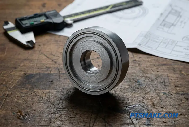
Achieving a reliable seal isn’t just about choosing the right seal; it’s about the precision of the housing itself. For robot joint sealing IP54 in Harmonic Drive Housings, machining is critical. The seal bore diameter, for instance, requires an H8 tolerance to ensure proper compression without damaging the seal.
Critical Machining Features
The depth of the seal bore is equally important for correct seating. We also machine a lead-in chamfer of at least 15 degrees with a specified radius. This subtle feature prevents the seal lip from being sliced or damaged during installation, a common cause of early failure.
Shaft and Bore Requirements
The output shaft’s surface finish where the seal contacts must be exceptionally smooth, typically between Ra 0.2-0.4μm, with no axial tool marks. A frequent mistake I see is a seal bore that isn’t perfectly aligned with the shaft’s axis. This lack of Concentricity9 causes uneven wear on the seal lip, leading to premature leaks. At PTSMAKE, we always verify this alignment between the seal bore and the shaft bearing bore. This is a non-negotiable quality check for us.
A robot’s reliability is directly linked to its IP rating, which in turn depends on the precision machining of its joint housings. Features like bore tolerance, surface finish, and concentricity are not minor details; they are fundamental to achieving long-term sealing performance.
Assembly Tolerance Stack — Why the Housing Is Not the Final Arbiter of Joint Accuracy
Many engineers focus solely on the housing’s precision, assuming it guarantees joint accuracy. However, even a perfectly machined housing can lead to a mediocre joint if the internal components are not carefully selected. The final accuracy is determined by a "tolerance stack"—the accumulation of small clearances and misalignments from every part in the assembly.
The Chain of Tolerances
Each component introduces a small amount of play. These individual tolerances, though minor on their own, add up to create a significant total error at the output.
Key Contributors to the Stack
| Component Fit | Typical Clearance/Play |
|---|---|
| Circular Spline to Housing Bore | up to 0.030mm |
| Cross-Roller Bearing Internal | 0.002 – 0.007mm |
| Output Shaft to Flexspline Alignment | 0.010 – 0.030mm |
| Motor Shaft to Wave Generator Bore | 0.020 – 0.050mm |
These values are not fixed but represent common specifications we encounter at PTSMAKE.
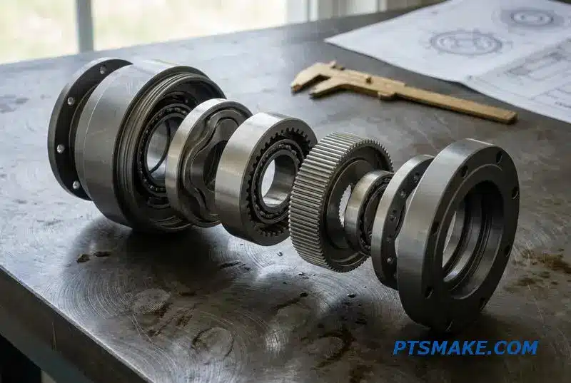
The real challenge in achieving high precision for Harmonic Drive housings isn’t just one dimension; it’s managing the interaction of multiple tolerances. Let’s break down how these seemingly tiny numbers combine to impact performance. A seemingly small clearance at each interface contributes to a larger, cumulative error.
Calculating the Total Stack-Up
A typical assembly might have a stack-up like this: 0.030mm (spline) + 0.005mm (bearing) + 0.020mm (output) + 0.030mm (motor) = 0.085mm total stack. This sum directly becomes Radial runout10 at the output flange, which is a critical measure of rotational inaccuracy.
From Stack-Up to Real-World Error
How does this 0.085mm affect a robot arm? For a link with a 100mm lever arm, this translates to a Total Indicated Reading (TIR) of 0.17mm (0.085mm x 2) at the end of the flange. This might seem acceptable, but it’s just for one joint.
In a multi-axis system, like a humanoid robot arm, this error multiplies. The inaccuracy from the first joint becomes the baseline error for the second, and so on. This cascade effect is why component selection for harmonic accuracy is as vital as the housing itself.
This demonstrates why a holistic view of the assembly tolerance is essential. Focusing only on the housing overlooks the compounded effect of bearing clearance, shaft fits, and fastener specifications. Each choice matters in the final robot arm accuracy tolerance chain.
Ultimately, the housing provides the foundation, but the final joint accuracy is a result of the entire tolerance stack. Careful component selection is just as critical as the precision machining of the housing itself to minimize output runout and ensure performance.
The Housing Design Review — Three Questions Every CNC Shop Should Ask Before Machining
When sourcing a supplier for Harmonic Drive Housings, the questions they ask are more revealing than the quote they provide. A shop that only looks at the 2D drawing without inquiring about the assembly is a major red flag. A truly competent partner understands that the housing is part of a complex system.
The Right Questions Signal Expertise
A proactive CNC shop will focus on fit and function. They should ask about mating components to ensure perfect integration. This approach moves beyond simply machining a part to delivering a component that functions flawlessly within the final robotic joint assembly.
Initial Supplier Litmus Test
Before you even get to pricing, listen for these critical inquiries. They separate a mere parts producer from a genuine manufacturing partner.
| Question Topic | Why It’s Important |
|---|---|
| Mating Parts | Verifies critical fits for bearings and splines. |
| Machining Setup | Ensures concentricity between critical bores. |
| Datum Sequence | Clarifies alignment for the entire gear assembly. |
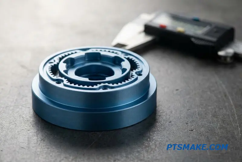
A silent supplier is a risk. We’ve seen projects fail because the machine shop didn’t ask about the functional assembly. They delivered a part that met the print, but it was useless because it didn’t integrate with the cross-roller bearing and circular spline. The right questions prevent these costly mistakes.
Digging Deeper: The Supplier Evaluation Checklist
Beyond the initial three questions, a capable shop will also probe into inspection and testing. They understand that verifying the part’s geometry is crucial. This is where the science of Metrology11 comes into play, ensuring that what is designed is what is delivered. A supplier’s ability to measure complex features is as important as their ability to machine them.
Advanced Capability Questions
You should also expect questions about post-machining verification. Can they measure deep bores accurately? Are they willing to perform functional tests with actual components? At PTSMAKE, we often insist on these steps to guarantee performance before shipping. This is a non-negotiable part of our quality process for critical components like Harmonic Drive Housings.
Here is a simple checklist to evaluate a potential CNC shop’s response:
| Evaluation Point | Ideal Response | Red Flag |
|---|---|---|
| Fit Verification | Asks for mating parts or to make a gauge. | Quotes directly from the print. |
| Datum & Setup | Inquires about assembly alignment. | Ignores functional datums. |
| CMM Capability | Confirms ability to measure deep features. | Vague about inspection methods. |
| Functional Test | Offers to test fit with the actual bearing. | Refuses any assembly-level check. |
The supplier’s questions reveal their depth of experience. A partner who engages in this level of detail is invested in the success of your final product, not just in shipping a piece of metal.
A supplier’s pre-quote questions are a direct indicator of their expertise. An engaged partner who asks about assembly, function, and inspection is focused on delivering a successful component, not just a machined part that technically matches a drawing.
Wire EDM vs Milling for Circular Spline Features — What Your Housing Drawing Should Say
When designing Harmonic Drive Housings with integral gear teeth, your drawing becomes the most critical document. The details you provide dictate the manufacturing method and final performance. Vague specifications lead to delays and costly errors. Precision is non-negotiable for these features.
Drawing Requirements for Integral Splines
For a housing with splines machined directly into the bore, Wire EDM is often the go-to for prototypes. Your drawing must clearly define the gear tooth geometry. Lacking any of this information will stop a project in its tracks.
| Specification | Typical Value / Standard |
|---|---|
| Tooth Profile Standard | ISO, DIN, or Customer-Defined |
| Module | 0.3-0.5mm for most robotics |
| Number of Teeth | Flexspline teeth + 2 (e.g., 122 vs 120) |
| Tooth Tip Diameter | Specified with tight tolerance |
| Root Diameter | Specified with tight tolerance |
| Root Fillet Radius | Often small, critical for strength |
Why This Detail Matters
For production, methods like gear shaping or Broaching12 are more common. However, for prototyping an integral circular spline, wire EDM is the standard. Every detail on the drawing is essential for creating an accurate quote and a functional part at PTSMAKE.
A common mistake I see is underspecifying the tooth profile. Merely stating a number of teeth isn’t enough. Without the module, pressure angle, and diameters, we cannot model the gear correctly. This is especially true for custom, non-standard tooth profiles.
The Non-Integral Alternative
For many projects, especially in prototyping phases for robotics, a non-integral design is a better path. Here, you use a pre-manufactured circular spline ring. The housing simply requires a precision pilot bore (H6/H7 tolerance) and a flat thrust face. This simplifies machining and allows you to use a matched harmonic component set, which is pre-calibrated for optimal performance.
Clear drawings for integral spline features are crucial for successful manufacturing. However, for prototypes, consider using a non-integral design with a matched component set to simplify the process and ensure performance, a strategy we often recommend to new clients in robotics.
How to Protect Your Design — NDA, Drawing Markup, and Serialization for Harmonic Housings
When you send designs for harmonic drive housings to a CNC shop, you’re sharing critical intellectual property. Protecting your joint architecture is essential. A multi-layered defense is the most effective way to secure your design from the initial quote to the final part delivery.
Key Protection Strategies
Your strategy should combine legal, informational, and physical controls. An NDA is the foundation, but it’s not enough on its own. Controlling what information you share and how you track physical parts is just as important for protecting your valuable designs.
A Practical Framework
Implementing a clear framework ensures every aspect of your IP is covered. Below is a breakdown of essential methods that we see effective clients use.
| Protection Layer | Method | Purpose |
|---|---|---|
| Legal | Non-Disclosure Agreement (NDA) | Establishes a legal framework for confidentiality. |
| Informational | Controlled Drawings & Split Mfg. | Limits the scope of information any single supplier receives. |
| Physical | Serialization & Scrap Control | Provides traceability and prevents unauthorized use of parts. |
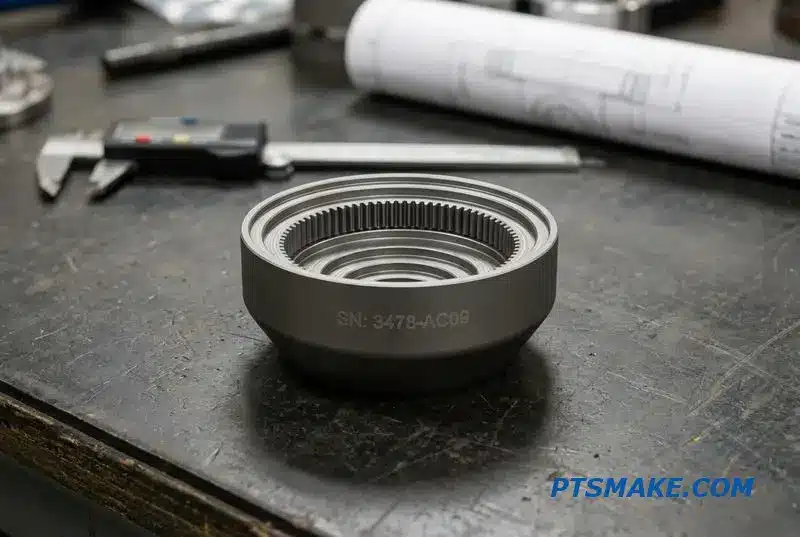
An NDA is the first step before sharing any CAD files or detailed drawings. At PTSMAKE, we consider this standard practice. Any professional CNC machining partner will sign one without hesitation, but true IP protection goes further and happens on the shop floor.
Beyond the NDA: Practical Protections
The most effective strategies limit what a supplier needs to know. For instance, instead of sending a complete 3D model, provide a 2D drawing with Geometric Dimensioning and Tolerancing13 for quoting non-critical features. This communicates all necessary manufacturing data without revealing the entire assembly.
Split Manufacturing
For maximum security, consider a split manufacturing approach for harmonic drive housings. Have one shop machine the main housing body and another produce the output flange. This compartmentalizes design knowledge, ensuring no single supplier has the complete picture. While it adds logistical complexity, it severely limits IP exposure.
Physical Part and Material Control
We also recommend machining a small pocket for a unique serial number on every housing. This provides critical traceability for quality control and batch tracking. Finally, always contractually require your supplier to either return all scrap material and rejected parts or provide a certificate of destruction. This closes a common but overlooked IP leak.
Protecting your harmonic drive housing designs requires more than just an NDA. A robust strategy combines legal agreements, controlled information sharing, and physical asset management. This multi-layered approach ensures your intellectual property remains secure from prototype to final production.

Understanding this effect is crucial for achieving high precision and repeatability in robotic actuators. ↩
Understanding this concept helps diagnose subtle vibration and performance issues in precision robotic systems. ↩
Understanding this contact stress helps in predicting bearing life and preventing premature failure. ↩
Explore how thermal equilibrium impacts high-tolerance machining for precision components. ↩
Understand how this fundamental property dictates material stiffness and its impact on engineering design. ↩
Learn how this tool precisely measures surface texture, a critical factor for seal life and performance. ↩
Understanding these microscopic peaks helps clarify how surfaces interact, affecting friction, wear, and sealing performance. ↩
Understanding tribology helps in designing components for minimal wear and friction, crucial for extending the operational life of robotic joints. ↩
Understanding this geometric tolerance is key to designing durable, high-performance rotating mechanisms. ↩
Understanding this concept helps quantify rotational inaccuracy and its impact on your assembly’s performance. ↩
Explore how the science of measurement ensures your parts meet critical design and functional requirements. ↩
Understand how this high-production machining process creates precise internal shapes and splines. ↩
Understand how this symbolic language ensures your design’s functional intent is perfectly translated into a physical part. ↩