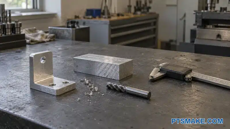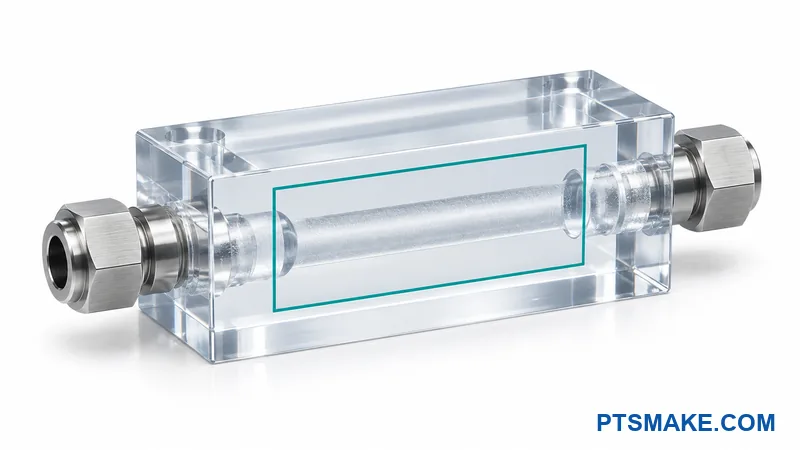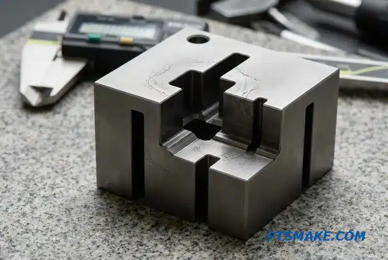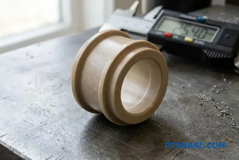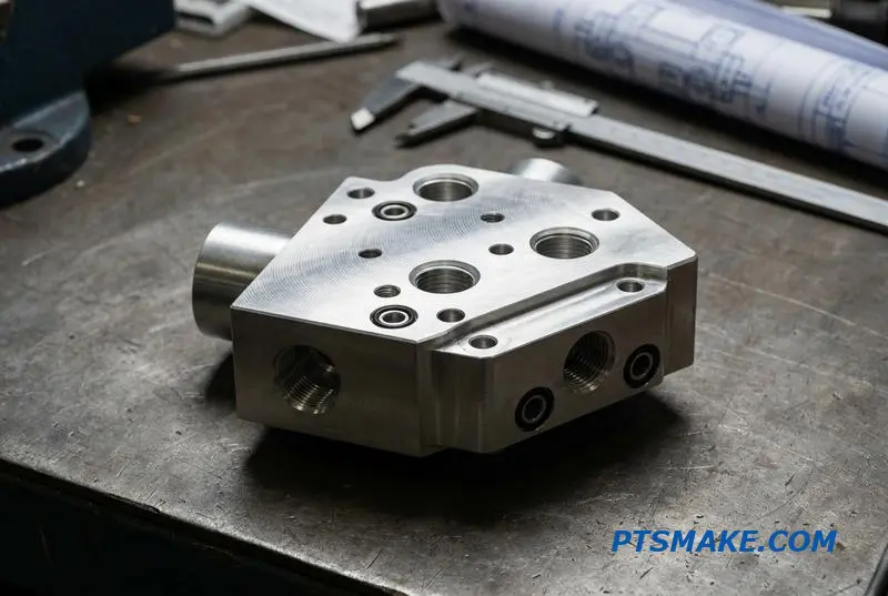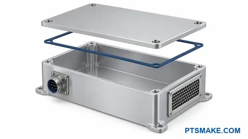

Building humanoid robot joints? A single bearing seat off by 0.05mm causes wrist sag, lost repeatability, and stripped threads in the field. Wrong material picks add weight your motors can’t carry.
Custom CNC machined humanoid robot joint components require 6061-T6 for housings, 7075 for structural flanges, and Ti-6Al-4V for high-stress shafts, with bearing bore tolerances of H6/H7, surface finish Ra 0.4-0.8μm, and GD&T-controlled stack-up under 0.05mm.
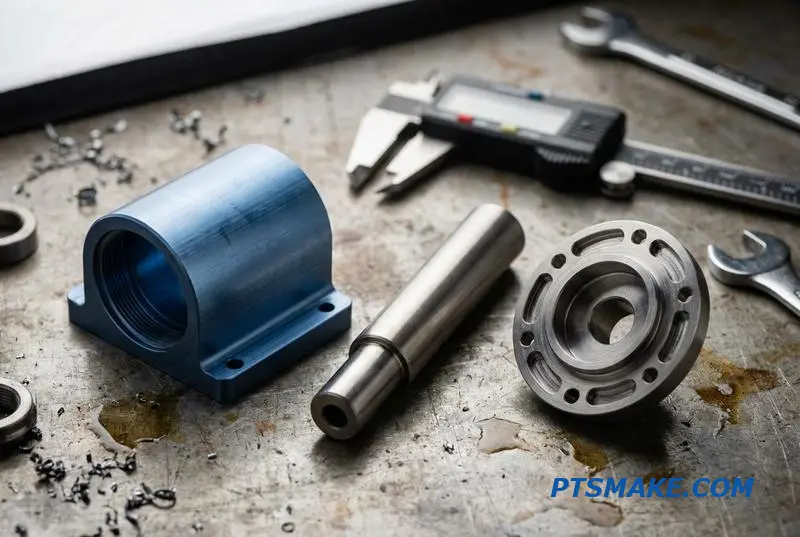
I have worked with robotics teams scaling from prototype to pilot runs, and the same questions come up: which material, which axis count, how to hold tolerance. Below, I break down each step with real numbers from the shop floor.
6061-T6 vs. 7075 Aluminum vs. Ti-6Al-4V — Choosing the Right Material for Each Joint Component
Selecting the right material for Humanoid Robot Joint Components is a critical decision. It directly impacts performance, durability, and cost. Each part of a robotic joint, from the housing to the output shaft, has unique demands. My goal is to clarify which material fits best for each application.
Key Material Candidates
This choice often comes down to three common alloys: 6061-T6 aluminum, 7075 aluminum, and Ti-6Al-4V titanium. Each offers a distinct balance of properties. Understanding these differences is key to optimizing your design for both function and manufacturing feasibility.
Initial Properties Overview
Let’s look at a high-level comparison.
| Material | Primary Use Case | Key Advantage |
|---|---|---|
| 6061-T6 | Housings, non-structural parts | Cost-effective & machinable |
| 7075 | Structural links, flanges | High strength-to-weight |
| Ti-6Al-4V | High-stress shafts, fasteners | Extreme strength & durability |
This table provides a starting point for evaluating the materials.
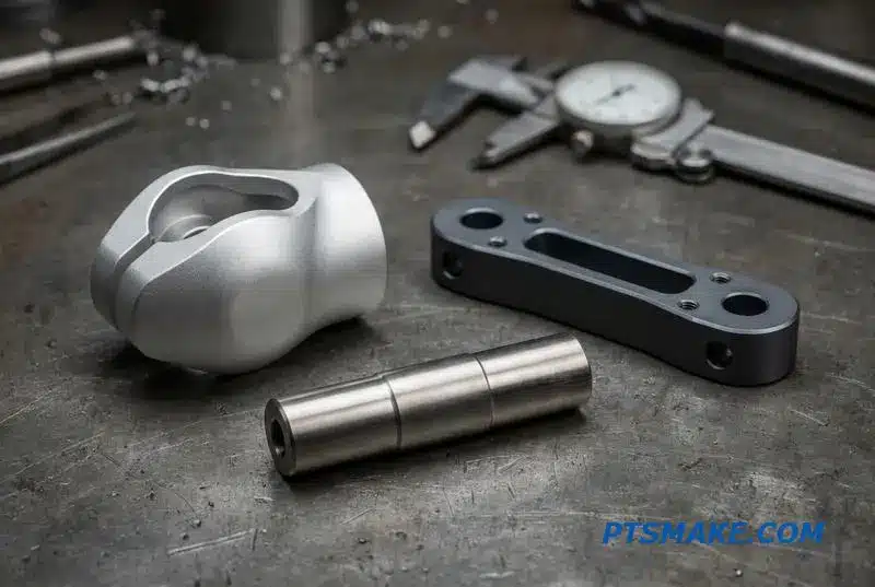
When engineering Humanoid Robot Joint Components, we must move beyond basic strength. Factors like fatigue resistance, machining difficulty, and material cost play a huge role in the final product’s success. It’s not always about picking the strongest material available.
Aluminum Alloys: 6061-T6 vs. 7075
6061-T6 is a workhorse for general-purpose parts like motor housings or mounting brackets. Its excellent machinability keeps production costs down, a significant factor we manage at PTSMAKE. However, its strength is limited. For components under significant bending loads, like output flanges, 7075 aluminum is a much better choice.
Its strength-to-weight ratio is far superior. But this comes with a trade-off. 7075 is more challenging to machine and is susceptible to stress corrosion cracking1 if not handled correctly. This is a critical consideration for parts under constant tension.
The Titanium Option: Ti-6Al-4V
For the most demanding applications, like high-stress shafts or critical fasteners, Ti-6Al-4V is often the only viable option. Its strength and fatigue resistance are exceptional, but it comes at a higher price. Our experience shows titanium CNC machining requires rigid setups and specific tooling, increasing manufacturing complexity.
| Feature | 6061-T6 Aluminum | 7075 Aluminum | Ti-6Al-4V |
|---|---|---|---|
| Weldability | Good | Poor | Fair (requires shielding) |
| Machinability | Excellent | Fair | Poor |
| Relative Cost | Base | ~1.5x Base | ~10x-15x Base |
| Corrosion Resistance | Very Good | Fair | Excellent |
This deeper comparison shows there’s no single "best" material.
Choosing between 6061-T6, 7075, and Ti-6Al-4V requires balancing performance, cost, and manufacturability. The ideal selection depends entirely on the specific application within the robotic joint, from low-stress housings to high-load structural components.
Tolerance Stack-Up in the Joint — Why ±0.05mm on a Housing Bore Can Break Your Robot
When designing Humanoid Robot Joint Components, we often focus on individual part precision. However, a single ±0.05mm tolerance on a housing bore seems insignificant. The real danger lies in how these small deviations accumulate across an entire assembly. This is called tolerance stack-up.
The Cumulative Effect
Imagine multiple components fitting together. Each part has its own tolerance range. The final assembly’s precision is not determined by the tightest tolerance but by the sum of all tolerances. A small error in one part can cascade, creating a much larger problem.
Simple Math, Big Problems
Let’s look at how this adds up.
| Component | Tolerance |
|---|---|
| Part A | ±0.05mm |
| Part B | ±0.05mm |
| Part C | ±0.05mm |
| Total Stack-Up | ±0.15mm |
As you can see, three simple parts can quickly create a significant deviation. This is a simplified view, but it highlights the core issue in a robotic joint.
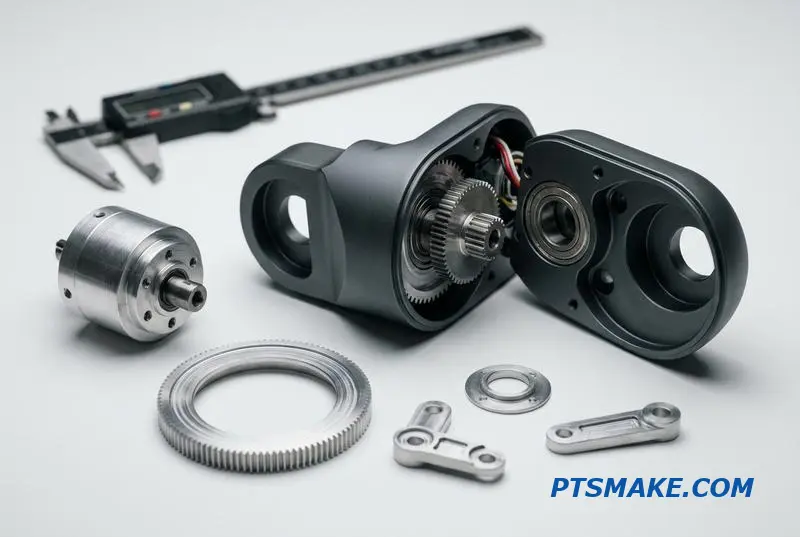
The real issue in humanoid joints is cumulative tolerance. It’s not just one bore. It’s the bearing seat bore tolerance, the shaft’s outer diameter tolerance, and even the parallelism of housing faces. All these individual deviations stack up, directly impacting final joint Backlash2.
A Real-World Numeric Example
Consider a robot joint with four bearing interfaces. If the CNC machining tolerance for each is a seemingly acceptable ±0.05mm, the potential radial play adds up. In a worst-case scenario, this creates a total deviation of 0.2mm before even considering the bearing’s internal clearance.
From Millimeters to Mission Failure
This 0.2mm of play might not sound like much. But extend that over the length of a humanoid arm, and it results in visible wrist sag. The robot’s end effector could be off by several millimeters, destroying its repeatability and ability to perform precise tasks.
| Tolerance Source | Max Deviation |
|---|---|
| Bearing Interface 1 | 0.05 mm |
| Bearing Interface 2 | 0.05 mm |
| Bearing Interface 3 | 0.05 mm |
| Bearing Interface 4 | 0.05 mm |
| Total Radial Play | 0.20 mm |
The GD&T Solution
This is why we rely on a Geometric Dimensioning and Tolerancing (GD&T) approach for robot arm components. Instead of simple +/- tolerances, we specify relationships like concentricity, true position, and parallelism. This controls how parts relate to each other, not just their individual sizes.
Individual tolerances stack up, turning minor deviations into major functional problems like joint play and reduced repeatability. A proper GD&T strategy is essential for controlling these cumulative errors in complex assemblies like Humanoid Robot Joint Components, ensuring performance meets design intent.
5-Axis vs. 3-Axis Machining for Complex Robot Joint Geometries
When manufacturing humanoid robot joint components, the choice between 3-axis and 5-axis machining is critical. These parts often feature complex geometries that are essential for function but challenging to produce. The right machining strategy directly impacts precision, cost, and lead time.
The Core Challenge: Intricate Designs
Humanoid robot joints demand organic shapes for weight reduction and internal channels for cables or cooling. These features are difficult to create with traditional methods. Choosing the wrong process can lead to multiple setups, tolerance stacking, and compromised structural integrity, which is unacceptable for robotic applications.
Choosing the Right Tool
The decision depends on part complexity and budget. While 3-axis machining is a foundational process, 5-axis technology opens up new possibilities for integrated designs. Understanding the trade-offs is key to success.
| Feature | 3-Axis Machining | 5-Axis Machining |
|---|---|---|
| Movement | X, Y, Z axes | X, Y, Z axes + 2 rotational axes |
| Best For | Prismatic parts, simple holes | Complex contours, undercuts |
| Setups | Multiple | Often a single setup |
| Cost | Lower hourly rate | Higher hourly rate, less setup time |
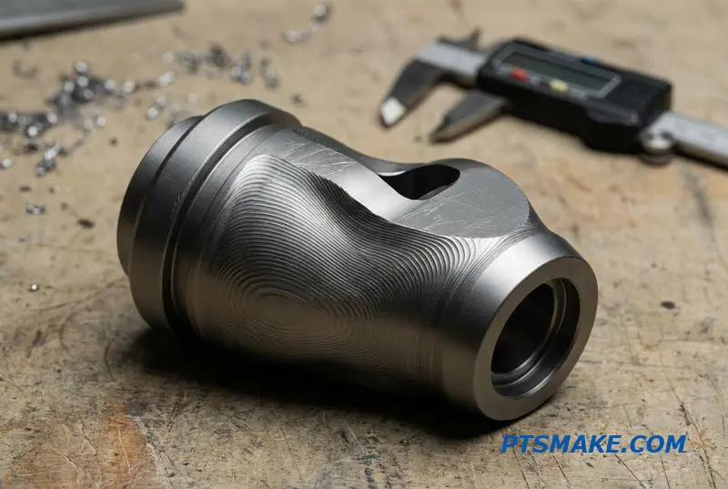
Many humanoid joint components require features like undercuts and angled pass-throughs. Here, 5-axis machining excels. Its ability to move the tool or workpiece on five axes simultaneously allows us to machine complex contours and deep cavities in a single setup, ensuring superior surface finish and accuracy.
Simultaneous vs. Indexed Machining
It’s important to distinguish between full 5-axis and 3+2 (indexed) machining. A 3+2 machine positions the part at a compound angle and then performs a 3-axis operation. This is great for simpler parts like a cylindrical actuator housing with angled threaded holes.
However, for a truly integrated housing with internal curved channels, full 5-axis is necessary. The continuous tool motion, guided by complex Interpolation3, is the only way to achieve a smooth, precise finish on those organic surfaces. At PTSMAKE, we guide clients through this choice to optimize their designs for manufacturability.
| Application Scenario | Recommended Process | Rationale |
|---|---|---|
| Simple actuator housing | 3+2 Axis | Cost-effective for prismatic shapes. |
| Integrated joint with internal channels | Full 5-Axis | Required for complex, organic contours. |
| Parts with multiple angled features | 3+2 Axis or 5-Axis | Depends on tolerance and surface needs. |
Based on our analysis, moving to 5-axis can add 15-30% to the machine time cost. However, it nearly eliminates errors from secondary operations and manual repositioning, providing better overall value for complex parts.
Choosing between 3-axis and 5-axis machining depends on the geometry of your humanoid robot joint components. For complex, integrated designs, 5-axis offers unmatched precision and efficiency, justifying the investment by reducing setups and improving part quality.
From Block to Joint — The CNC Manufacturing Process for a Robot Actuator Housing
Transforming a solid block of 7075 aluminum into a precise humanoid robot joint component is a detailed process. It begins with raw stock and ends with a finished part meeting tight tolerances. Each step requires careful planning and execution for optimal results.
The Transformation Journey
The journey from a simple block to a complex housing involves several key manufacturing stages. We ensure precision at every phase to guarantee the final part’s integrity and performance. This is critical for Humanoid Robot Joint Components that demand reliability.
Key Machining Stages
| Stage | Description | Key Focus |
|---|---|---|
| Preparation | Squaring the block and establishing datums. | Foundational accuracy. |
| Roughing | High-speed removal of bulk material. | Efficiency and stability. |
| Finishing | Achieving final dimensions and surface finish. | Precision and quality. |
| Inspection | Verifying all features against the print. | Quality assurance. |
This structured approach ensures that every actuator housing we produce at PTSMAKE meets the exacting standards required for modern robotics applications.
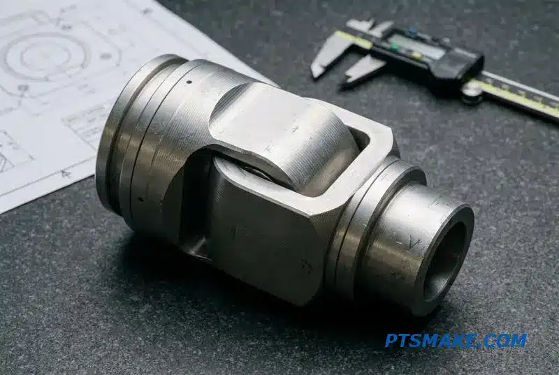
The complete actuator housing machining sequence requires precision from start to finish. For a typical medium-complexity part, the cycle time in our shop is around 45 to 90 minutes. We start by facing and squaring the 7075 aluminum bar stock to create a perfect reference.
Initial Machining and Roughing
Next, we rough out the large internal cavity. We use trochoidal toolpaths4 to manage tool engagement and clear chips effectively. High-pressure coolant is essential here, as it prevents chip welding in deep pockets. This is a critical step in the CNC machining process for a robot actuator housing.
The Step-by-Step Sequence
| Step | Operation | Tooling Used |
|---|---|---|
| 1 | Facing and Squaring | Face Mill |
| 2 | Roughing Internal Cavity | High-Speed End Mill |
| 3 | Semi-Finishing Bore | Boring Head |
| 4 | Drilling and Tapping | Drill and Tap Set |
| 5 | Finishing Flange Face | Finishing End Mill |
| 6 | Machining Cable Slots | Small Diameter End Mill |
| 7 | Final Bore Finishing | CBN Insert |
After roughing, we semi-finish the bearing bore and then drill and tap all threaded holes. We then flip the part to machine features like cable pass-through slots. Finally, a Cubic Boron Nitride (CBN) insert is used for the final bore finishing to achieve a perfect fit and surface.
The entire process converts a solid block into a complex, high-precision robot actuator housing. This transformation relies on a carefully planned sequence of CNC operations, from initial roughing to the final finishing touches, ensuring every component meets strict performance and quality standards.
Bearing Seat Machining — Why Surface Finish and Roundness Determine Joint Life
In components for humanoid robots, the bearing seat is where precision matters most. Poor surface finish or out-of-spec roundness directly causes premature wear, vibration, and eventual joint failure. The tolerances are non-negotiable for achieving a reliable service life and smooth operation.
The Role of Surface Finish
A proper surface finish, typically Ra 0.4-0.8μm, ensures the bearing’s outer race has maximum contact with the seat. A rougher surface reduces the contact area, creating high-stress points that can lead to micro-fretting and material fatigue over millions of cycles.
Why Roundness is Critical
Even with a perfect finish, a non-circular bore prevents uniform load distribution. A roundness tolerance of 0.005mm is standard for these applications. Exceeding this causes uneven pressure on the bearing, leading to accelerated wear on one side and compromising the entire joint’s accuracy.
| Feature | Poor Machining Effect | Consequence |
|---|---|---|
| Surface Finish | High Ra value (>0.8μm) | Reduced contact, stress points |
| Roundness | Oval or lobed bore | Uneven bearing load, vibration |
| Diameter | Incorrect fit (too tight/loose) | Bearing damage, slippage |
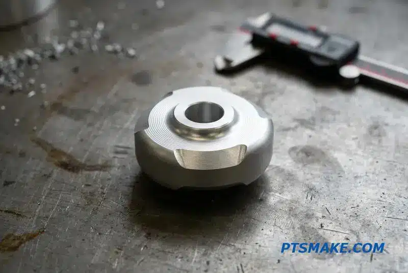
Achieving the required specifications involves selecting the right machining strategy. Not all methods produce the same result, and thermal conditions play a significant role, especially with materials like aluminum used in humanoid robot joint components. Understanding these factors is key to successful manufacturing.
Machining Method Comparison
Boring is often the best method for achieving superior roundness and finish in a bearing bore. Unlike reaming, which can follow the path of a pre-drilled hole, boring uses a single-point tool to generate a truer circle. Fine milling can also be used, but controlling the surface finish to Ra 0.8μm is challenging.
| Method | Typical Roundness | Typical Finish (Ra) | Key Advantage |
|---|---|---|---|
| CNC Boring | < 0.005mm | 0.4 – 0.8μm | Best geometric accuracy |
| Reaming | 0.005 – 0.015mm | 0.8 – 1.6μm | Speed and efficiency |
| Fine Milling | 0.010 – 0.020mm | > 1.6μm | Versatility for features |
Managing Thermal Expansion
Thermal expansion is a critical, often overlooked, variable. For aluminum, the Coefficient of Thermal Expansion (CTE)5 is approximately 23μm/m/°C. A part machined at 20°C that operates at 50°C will expand. For a 50mm bearing seat, this 30°C change means the diameter grows by about 0.0345mm, drastically altering the fit. We always recommend a roughing pass, allowing the part to thermally stabilize, followed by a final finishing pass to hold tight tolerances.
Achieving a reliable bearing fit goes beyond basic diameter control. It demands a holistic approach, considering surface finish, roundness, and thermal expansion. Selecting the right machining process, like CNC boring, is essential for components that require long-term precision and performance.
Threaded Inserts and Helicoils — Why They Matter More in Humanoid Joints Than Any Other Application
Stripped threads in aluminum housings are a recurring headache in robot prototyping. One failed thread can sideline a component during assembly or field service. The solution lies in choosing the right fastener strategy from the start, especially for critical humanoid robot joint components.
Thread-Forming Screws vs. Helical Inserts
Your choice depends on the aluminum alloy and expected service life. Thread-forming screws are excellent for softer materials like 6061, as they cold-form threads without creating chips. For harder 7075 aluminum or joints requiring repeated disassembly, stainless steel helically coiled inserts are necessary.
| Feature | Thread-Forming Screw | Helically Coiled Insert (Helicoil) |
|---|---|---|
| Best For | Softer Aluminum (e.g., 6061) | Harder Aluminum (e.g., 7075) |
| Process | Cold-forms threads, no chips | Provides durable steel threads |
| Use Case | Permanent or limited assembly | Frequent disassembly & reassembly |
| Strength | Moderate pull-out strength | High pull-out and wear resistance |
This decision is fundamental for the longevity and serviceability of the joint.
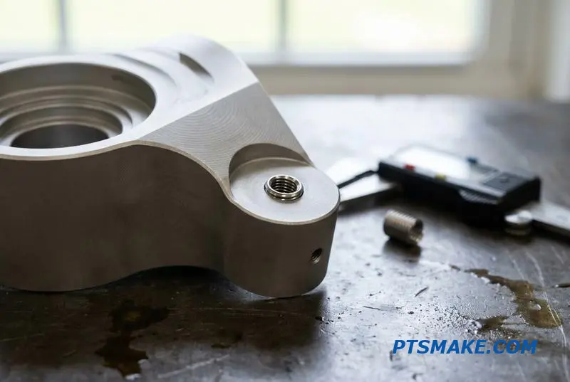
Design and Machining Considerations
Making the right choice early in the design phase prevents costly failures later. Based on our work with robotics clients, we recommend specifying threaded inserts for any bolted interface that will be disassembled more than five times. This is common during R&D. Also, use them when bolt torque exceeds 10 Nm in an aluminum part.
Material Interaction and Machining
Thread-forming screws displace material rather than cutting it. This process works well in ductile 6061 aluminum. However, in harder 7075, it can induce stress and lead to cracking. For these applications, a helicoil provides a robust stainless steel thread, preventing wear and Galling6 against steel bolts.
The Importance of Precision Machining
Machining the hole for an insert is not a standard tap operation. The CNC program must call out the specific hole size and thread for the insert, often using an STI (Screw Thread Insert) tap. At PTSMAKE, we know that precision in the insert bore machining is critical. An incorrect bore compromises the entire joint’s strength.
| Guideline | Condition for Threaded Inserts | Rationale |
|---|---|---|
| Serviceability | Disassembled > 5 times in its life | Prevents thread wear in aluminum housings |
| Torque Specs | Bolt torque exceeds 10 Nm | Aluminum threads can strip under high clamp loads |
| Material | Using 7075-T6 aluminum | Harder alloy requires a stronger thread interface |
Choosing between a simple tapped hole and an insert is a key decision for any high-performance humanoid robot joint.
Selecting the correct threading method from the start is vital for the long-term reliability and serviceability of humanoid robot joints. This decision impacts everything from prototype iteration speed to the final product’s field performance, making it a critical consideration for designers.
Weight Reduction Without Sacrificing Stiffness — Pocketing, Ribs, and Organic Lattice Patterns
In designing Humanoid Robot Joint Components, every gram matters. Weight saved in a robot’s arm reduces the torque required from every motor up the kinematic chain, improving efficiency and performance. The challenge is removing mass without compromising the stiffness needed for precise movements.
Foundational Strategies
Pocketing is the most direct approach. We machine away material from areas that don’t bear significant loads, like the internal walls of an actuator housing. For greater stiffness with less weight, we often machine ribbed structures instead of leaving a full-thickness wall. This creates a strong skeleton.
Comparing Common Techniques
| Technique | Weight Reduction | Machining Complexity |
|---|---|---|
| Pocketing | Moderate | Low to Medium |
| Ribbing | High | Medium |
| Thin-Web | High | High |
| Lattice | Very High | Very High (5-Axis) |
These methods are fundamental for creating lightweight robot joint components. The key is choosing the right strategy based on the specific load case and manufacturing constraints of the part.
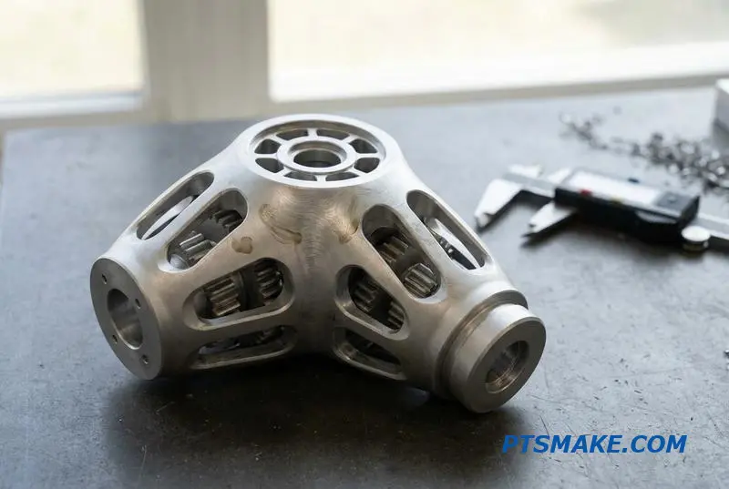
Achieving significant weight reduction requires moving beyond simple pockets. This is where advanced CNC machining techniques become critical, especially for parts like motor mounts or structural limbs where stiffness is non-negotiable. It’s a balance of aggressive material removal and precise control.
Advanced Machining and Tooling
Thin wall aluminum machining, down to 0.5mm, is highly effective but introduces risks like chatter and distortion. At PTSMAKE, we control this using variable helix end mills that disrupt harmonic vibrations. This allows us to create extremely light yet rigid parts.
For the most demanding applications, we use 5-axis machining to create organic lattice or fin patterns. These intricate structures, guided by Finite Element Analysis (FEA)7, mimic bone growth, placing material only where it’s structurally necessary. This not only maximizes the stiffness-to-weight ratio but also increases surface area for better passive cooling.
Specialized Tool Selection
| Application | Recommended Tool | Key Benefit |
|---|---|---|
| Deep Pocket Milling | Necked-Down End Mill | Avoids shank rubbing on deep walls |
| Thin Wall Finishing | Variable Helix End Mill | Suppresses chatter and vibration |
| Organic Lattices | Ball Nose End Mill (5-Axis) | Enables complex, smooth contours |
These tooling choices are essential when executing a pocket milling actuator housing or any other complex component where precision and surface finish are paramount.
Effective weight reduction combines smart design with advanced manufacturing. Techniques like pocketing, ribbed structures, and 5-axis organic lattices allow for lighter, more efficient Humanoid Robot Joint Components without sacrificing the critical stiffness needed for reliable operation in demanding applications.
Surface Finishing for Robot Joint Components — Hard Anodizing, Micro-Arc Oxidation, and Dry Film Lubricants
Aluminum is a top choice for robot joints due to its light weight, but its softness is a liability. For Humanoid Robot Joint Components, surface treatments are not optional; they are essential for durability. The right finish prevents wear and ensures long-term performance.
Key Surface Hardening Options
Hard anodizing and micro-arc oxidation are two primary methods we use. Both create a hard, wear-resistant layer integral to the aluminum substrate. Each serves different performance requirements, especially under high-load conditions found in modern robotics.
Comparing Anodizing and MAO
Here is a quick comparison based on projects we’ve handled at PTSMAKE.
| Feature | Hard Anodizing (Type III) | Micro-Arc Oxidation (MAO) |
|---|---|---|
| Typical Thickness | 25-50 µm | 50-100 µm |
| Surface Hardness | 60-70 HRC | > 70 HRC |
| Best For | Bearing surfaces, general wear | High-torque, high-impact joints |
| Appearance | Dark gray to black | Off-white to gray ceramic |
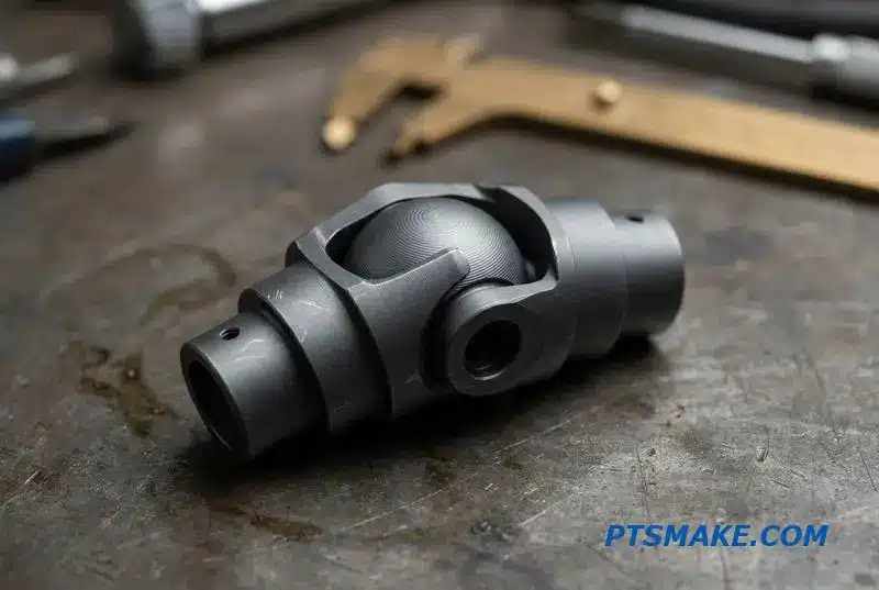
Choosing the right treatment goes beyond hardness. The application dictates the best choice. A hard anodizing robot joint process (MIL-A-8625 Type III) is excellent for bearing surfaces and general sliding wear, providing a reliable protective layer.
Practical Design Considerations
However, coatings add material. This is a critical detail for precision fits. Bearing bores and threaded holes will lose their required tolerance if coated. We always advise clients to design with a 0.05mm allowance or plan for post-coat reaming to restore dimensions. Masking these critical features before treatment is standard practice.
Advanced Solutions for Extreme Conditions
For joints experiencing very high torque, a surface finish actuator housing benefits more from Micro-Arc Oxidation8. This process creates an even harder ceramic layer. For components like shafts where replacing stainless steel is desired, electroless nickel plating offers superior corrosion resistance and hardness.
Internal Friction Management
Internal sliding surfaces present another challenge. Here, we apply dry film lubricants. Molybdenum disulfide or PTFE-impregnated coatings create a low-friction surface without attracting debris. These dry film lubricant CNC parts are essential for smooth, maintenance-free operation inside an enclosed joint.
| Treatment Type | Primary Application | Key Benefit |
|---|---|---|
| Masking | Bearing bores, threads | Maintains critical tolerances |
| Electroless Nickel | Shafts, pins | Corrosion resistance, hardness |
| Dry Film Lubricant | Internal sliding parts | Reduces friction, no grease |
Selecting the right surface treatment is crucial for the durability of Humanoid Robot Joint Components. Hard anodizing, MAO, and dry film lubricants each have specific roles. Careful planning for tolerances and masking is essential for achieving optimal performance and component longevity.
The Role of Swiss Machining in Small Humanoid Joint Parts — Pins, Shafts, and Precision Dowels
Humanoid robot joint components aren’t just about milled housings. The smaller, intricate parts like pins, shafts, and dowels are equally critical. For these, Swiss-type lathes are often the best solution, delivering exceptional precision for small CNC parts in humanoid robots.
Swiss vs. Conventional Turning
Swiss machining excels where conventional turning struggles. It’s designed for small, complex parts that require high accuracy. This method is essential for components with tight tolerances, ensuring flawless interaction within a robotic joint assembly. The main differences are clear when you look at their capabilities.
| Feature | Swiss Machining | Conventional Turning |
|---|---|---|
| Part Support | Guide bushing supports workpiece | Chuck holds one end |
| L:D Ratio | Ideal for >5:1 | Best for <5:1 |
| Tolerance | As tight as ±0.005mm | Typically ±0.025mm |
| Complexity | Handles multi-axis features easily | Limited to simpler geometries |
At PTSMAKE, we leverage Swiss machining for these demanding applications. It guarantees the stability and performance needed for precision turned joint components.
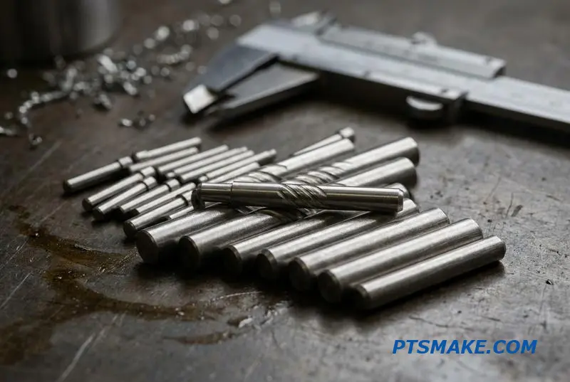
When to Specify Swiss Machining
Deciding between Swiss and conventional turning comes down to a few key factors. If a part’s length is more than five times its diameter, Swiss machining is the clear choice. The guide bushing provides support, preventing deflection and maintaining accuracy along the entire length.
Critical Geometric Tolerances
For parts with multiple diameters, like encoder shafts, maintaining perfect alignment is crucial. Swiss machines excel at holding tight Concentricity9, often better than 0.01mm. This ensures smooth rotation and prevents vibration, which is vital for the performance of humanoid robot joint components. We also use them for parts requiring cross-drilled holes or milled flats.
Material Choices for Joint Components
Material selection directly impacts durability and performance. Based on our work with clients, we have found specific materials work best for different applications. The right material choice is fundamental to the longevity and reliability of Swiss machining robot parts.
| Component | Material | Key Benefit |
|---|---|---|
| Dowel Pins | Ground 303 Stainless | Corrosion resistance and smooth finish |
| High-Strength Shafts | 17-4PH H900 | High tensile strength and hardness |
| Couplings | 4140HT Alloy Steel | Excellent fatigue and impact resistance |
Selecting the correct material from the start avoids costly failures later. This expertise is a core part of how we approach every project.
Swiss machining is indispensable for small, complex humanoid robot joint components. It delivers superior precision for parts with high length-to-diameter ratios, tight concentricity requirements, and complex features. Proper material selection further ensures the durability and reliability of these critical parts.
EDM for Intricate Joint Features — Splines, Internal Hexes, and Tight-Entry Slots
While CNC milling is a versatile process, it has limitations when producing certain intricate features for humanoid robot joint components. Some geometries are either impossible or simply uneconomical to machine conventionally, pushing us toward specialized methods.
When Traditional Machining Falls Short
Features like internal splines, blind hexagonal pockets, and deep, narrow slots present significant challenges. Milling tools require clearance and cannot create sharp internal corners or access tight, enclosed spaces without compromising the part’s integrity or incurring prohibitive costs.
The EDM Solution
Electrical Discharge Machining (EDM) excels where milling cannot. It uses thermal energy to remove material, allowing for the creation of complex internal shapes with high precision, regardless of material hardness. This makes it ideal for specialized joint components.
| Feature Type | Conventional Milling Challenge | EDM Solution |
|---|---|---|
| Internal Splines | Requires special tooling (broaching) | Wire EDM creates precise profiles |
| Blind Hex Sockets | Impossible to mill sharp corners | Sinker EDM forms perfect shapes |
| Deep, Narrow Slots | High tool breakage risk | Wire EDM cuts with no mechanical stress |
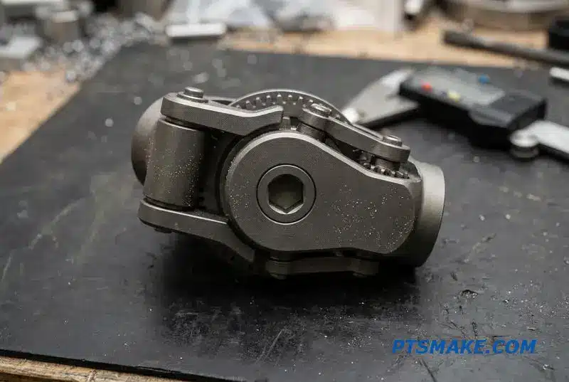
For complex robot joint parts, we must choose between Wire EDM and Sinker EDM. Each serves a distinct purpose in precision manufacturing. Understanding their applications ensures we produce features correctly and cost-effectively from the start.
Wire EDM for Through-Features
Wire EDM is perfect for cutting through an entire component, creating intricate profiles. We often use it for internal splines in hardened steel drive shafts for humanoid robot joints. A thin, electrically charged wire acts as the cutting tool, delivering exceptional accuracy for continuous shapes.
Sinker EDM for Blind Cavities
Sinker EDM, or die-sinking, is the solution for blind, non-through features. For a sinker EDM hex pocket actuator output, we machine a custom electrode in the shape of the hex. The process uses controlled electrical sparks submerged in a Dielectric fluid10 to erode material, forming the pocket without mechanical contact.
Cost and Speed Considerations
EDM is slower than milling; a typical wire EDM feed rate is only 3-10 mm²/min. However, for features that would otherwise require broaching or multiple complex milling setups, EDM becomes the most economical choice. It turns impossible designs into finished EDM robot joint parts.
| Process | Best For | Typical Application | Key Advantage |
|---|---|---|---|
| Wire EDM | Through-cut profiles | Internal splines, keyways | High precision on hardened materials |
| Sinker EDM | Blind cavities, complex shapes | Hexagonal sockets, molds | Creates features inaccessible to cutters |
For intricate internal features where milling is impractical, EDM is the essential method. It delivers precision for geometries like splines and blind pockets, enabling the advanced component designs required for modern humanoid robot joint components and actuators.
From Prototype to Pilot Run — Scaling CNC Joint Components Without Redesigning
Hardware startups often face a major hurdle when scaling production. A CNC machined prototype works perfectly, but moving to a pilot run creates challenges in maintaining tolerances and controlling costs. The key is that the initial work is not wasted.
The Power of Validated Processes
The beauty of CNC machining lies in its digital foundation. Once a CAM program and fixturing setup are validated for a prototype, they are ready for a larger run. This direct path avoids costly and time-consuming redesign phases entirely.
Scaling Without Starting Over
For components like those in humanoid robots, this is a significant advantage. The path from a few units to a few hundred is clear and predictable. The core manufacturing process remains consistent, ensuring quality is maintained.
| Aspect | Prototype (10 units) | Pilot Run (200 units) |
|---|---|---|
| Design File | Finalized CAD | Unchanged |
| CAM Program | Validated | Reused |
| Fixturing | Proven | Reused |
| Tolerances | Achieved | Maintained |
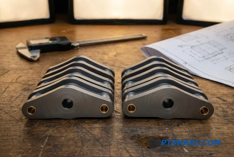
Scaling from prototype to pilot run is not just about repeating the same steps. True efficiency comes from targeted optimization. This is where we shift our strategy from simply making a part to manufacturing it efficiently at a higher volume.
Strategic Material Sourcing
For ten prototypes, we might buy material from a local stockist. For 200 units, we can place a mill-order for raw materials. This shift to bulk purchasing is one of the primary drivers of cost reduction per part.
Optimizing Cycle Time
We also refine the manufacturing process itself. This includes creating multi-part fixturing to machine several components in a single setup. We also optimize feed rates and toolpaths, which shaves valuable seconds or minutes off each part’s cycle time. This is a critical step for low volume robot component manufacturing.
After collaborating with clients on these optimizations, we have seen how a few key adjustments deliver major results. The high initial setup cost is spread across more units. This concept of Setup Amortization11 combined with bulk material pricing, is how we achieve significant savings. This advantage makes CNC machining ideal for scaling humanoid robot manufacturing compared to casting, which requires expensive molds and long lead times.
| Cost Factor | Prototype (10 units) | Pilot Run (200 units) |
|---|---|---|
| Setup Cost/Unit | High | Low |
| Material Cost/Unit | Standard | Reduced (Bulk) |
| Cycle Time/Unit | Baseline | Optimized (Lower) |
| Total Unit Cost | Reference | ~40% Reduction |
CNC machining offers a direct, efficient path from a single prototype to a pilot run. By reusing validated programs and optimizing material sourcing and cycle times, startups can scale production of Humanoid Robot Joint Components without redesign, saving significant time and capital.
CMM Inspection Protocol for Robot Joint Components — What Gets Measured and Why
A detailed CMM inspection protocol is non-negotiable for producing reliable humanoid robot joint components. The process ensures every feature critical to performance meets strict specifications. At PTSMAKE, we focus on a systematic workflow that leaves no room for error, as small deviations can lead to significant performance issues.
Key CMM Inspection Points
Our quality control process for CNC robot parts is built around several critical measurements. Each point directly impacts the final assembly’s function and longevity. Minor errors in these areas can cause binding, vibration, or premature failure.
Geometric and Positional Checks
The following table outlines the essential checks we perform on every joint component. This systematic approach to CNC machining quality assurance for robotics guarantees that parts fit and function as designed, ensuring smooth and precise movement in the final assembly.
| Measurement Point | Critical Feature | Reason for Inspection |
|---|---|---|
| Bearing Bore | Diameter & Roundness | Ensures proper bearing fit and smooth rotation. |
| Flange Face | Parallelism to Bore Axis | Prevents misalignment and uneven load distribution. |
| Threaded Holes | True Position | Guarantees correct alignment with mating components. |
| Encoder Seat | Flatness & Height | Critical for accurate position feedback from the encoder. |
Understanding Measurement Limitations
While a CMM is a powerful tool, it’s important to understand its limitations and the concept of measurement uncertainty. A typical CMM has an accuracy of around 2.5μm + L/300. For a standard tolerance of ±0.01mm, this gives us a Test Uncertainty Ratio (TUR)12 of 4:1, which is widely accepted.
This ratio means the measurement device is four times more precise than the tolerance it is verifying. It provides confidence in the inspection results for most features on humanoid robot joint components. However, for extremely tight tolerances, we need to consider other methods.
When to Use Alternative Gauging
In our experience, a CMM may not be the best tool for every job. Specifically, for bearing bores with tolerances below 6μm, we often turn to a more specialized instrument.
| Method | Best Application | Tolerance Range |
|---|---|---|
| CMM Inspection | General geometric & positional features | > ±0.006mm |
| Air Gauge | High-precision bores | < ±0.006mm |
Using an air gauge for the bearing bore in these cases provides faster, more repeatable measurements for such a critical feature. This dual-pronged approach to quality control ensures every aspect of the CNC part meets the highest standards.
A robust quality control workflow, using both CMM inspection and specialized tools like air gauges when necessary, is fundamental to producing high-performance robot joints. It guarantees that every critical dimension and geometric tolerance is verified, ensuring reliability from prototype to production.

Understanding this phenomenon is crucial for ensuring long-term reliability in high-strength aluminum parts. ↩
Understanding backlash sources is key to designing high-precision, zero-play robotic motion control systems. ↩
Understanding how machines create curves helps evaluate a supplier’s capability for complex geometries. ↩
Explore how this toolpath enhances machining speed and prolongs tool life in demanding materials. ↩
Understanding CTE helps in designing assemblies that maintain precise fits across varying operational temperatures. ↩
Understanding this metal adhesion phenomenon is key to preventing seized fasteners in high-stress robotic applications. ↩
Learn how this simulation predicts stress and strain to optimize part design before machining. ↩
Understand how this electrochemical process transforms aluminum surfaces into a hard, dense ceramic oxide layer for extreme wear resistance. ↩
Understanding this geometric tolerance is crucial for designing high-performance rotating assemblies and preventing premature component wear. ↩
Explore how this non-conductive liquid enables spark erosion, a fundamental concept in high-precision, non-contact machining. ↩
Understanding this helps calculate true cost savings when scaling production volumes. ↩
Understanding this ratio helps ensure your measurement tools are sufficiently accurate for specified tolerances. ↩