
5-Axis CNC Machining Services for Complex Parts
Complex surfaces, angled features and multiple machined faces, made to your drawings. PTSMAKE specializes in simultaneous 5-axis machining, with 3+2 positioning when it suits the part. Dimensional tolerances as tight as ±0.005 mm on suitable features, subject to drawing and material review.
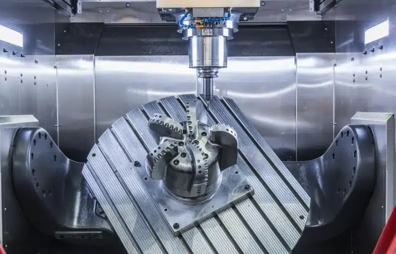
- Simultaneous 5-axis & 3+2
- Complex curves & angled features
- Prototype to production orders
- Drawing-based inspection
Why Choose PTSMAKE for 5-Axis Machining?
Start with the surfaces, fits and feature relationships your part needs. Then choose the machining route that delivers them.
Continuous Control for Complex Surfaces
Use changing tool angles where a fixed direction limits access to curved walls, sculpted faces or deep features.
Review Your GeometryFewer Datum Transfers
Machining several accessible faces in one clamping can reduce repositioning errors. Plan how the final clamped face will be finished.
Discuss Critical FeaturesPractical Feedback Before Cutting
Review holder clearance, thin sections and gripping surfaces. Any proposed design change goes to you for approval.
Solicite uma Revisão de DesignAcceptance Defined Up Front
Agree the drawing revision, critical measurements and finished condition so the quote and inspection target the same requirements.
Plan Your InspectionQuality Control for Complex 5-Axis Parts
Size, position and surface shape are separate requirements. A ±0.005 mm dimensional capability does not define every geometric tolerance on the part.
Inspect the Features That Make the Part Work
A housing may need angled holes to meet a shared datum. A contoured component may need its surface profile checked against the CAD model. Identify these requirements before choosing the measurement plan.
Specify the material condition, datum system, critical dimensions and final finish. Agree methods, sampling and reporting during quotation, including any checks needed after unclamping or coating.
- Desenho e MaterialRevisão, liga, condição e características críticas.
- Configuração e Primeira PeçaHolding surfaces and the datum transfer plan.
- Verificações em ProcessoFeatures affected by wear or later operations.
- Aceitação FinalFinished dimensions, appearance and agreed records.
| Caraterística | O que pode dar errado | What to specify |
|---|---|---|
| Angled bores & cross-face holes | Correct diameters but incorrect location or orientation. | Datum references, position/orientation requirements and a suitable measurement method. |
| Freeform & contoured surfaces | A smooth-looking surface that differs from the intended shape. | CAD revision, surface profile requirements and the regions to measure. |
| Thin walls & slender features | Clamping or material removal changes the released shape. | Wall limits, support during inspection and acceptance in the final condition. |
| Coated fits & mating faces | Finishing changes size, edge condition or contact surfaces. | Final dimensions, masking areas and any post-finish checks. |
Materials for 5-Axis CNC Machining
The right material must suit both the working part and its complex geometry. Include the exact grade and material condition in your enquiry.
Ligas de alumínio
- Typical consideration
- Low weight for contoured housings, brackets and moving components.
- Review for five-axis work
- Thin-wall stability, deep-pocket access and distortion after material removal.
Specify the alloy, temper and any anodized surfaces.
Aço inoxidável
- Typical consideration
- Corrosion resistance for complex parts with exposed or wetted surfaces.
- Review for five-axis work
- Grade, cutting access and the edge condition of intersecting features.
State the service environment and any passivation requirements.
Ligas de titânio
- Typical consideration
- Strength and weight requirements in a demanding service environment.
- Review for five-axis work
- Tool engagement, heat control and support around slender sections.
Confirm the grade, stock specification and critical geometry with us.
Alloy & Tool Steels
- Typical consideration
- Load-bearing, wear or hardness requirements for shaped components.
- Review for five-axis work
- Material condition and how heat treatment affects final machining.
Include the required final hardness and any finish-machining allowance.
Brass & Copper Alloys
- Typical consideration
- Electrical, thermal or fluid-interface requirements.
- Review for five-axis work
- Alloy-specific machinability, burrs and protection of delicate features.
Use an exact grade; conductivity and strength vary by alloy.
Plásticos de engenharia
- Typical consideration
- Low weight, insulation or sliding contact in contoured parts.
- Review for five-axis work
- Clamping deformation, thermal response and dimensional conditioning.
Include operating temperature, loads and required fit limits.
Surface Finishes for Complex Geometry
Define the finish by functional surface. Angled holes, curved faces and recessed areas may need different protection or acceptance criteria.
| Surface requirement | Opções para discutir | Detail to include in your drawing |
|---|---|---|
| Machined contours & mating faces | As-machined finish; local finish machining. | Required roughness, tool-mark direction where functional, and surfaces that must remain untouched. |
| Aluminum protection & appearance | Anodizing; bead blasting before anodizing where appropriate. | Coating specification, color, contact/racking locations and masking of precise fits. |
| Stainless surfaces | Passivation to the agreed specification. | Alloy, cleanliness requirements and access for treating and rinsing recesses. |
| Wear or corrosion protection | Suitable plating or coating after material review. | Thickness limits, accessible internal surfaces and dimensions after finishing. |
| Visible sculpted faces | Local polishing or a defined cosmetic texture. | Approved appearance reference, protected edges and profile tolerances that must be preserved. |
5-Axis CNC Machining Production Lead Times
Plan your order from urgent prototypes through repeat production.
Protótipos Urgentes
1–3 diasFor urgent parts after geometry, material and scheduling review.
Pequenos Lotes
7–15 diasCoordinate setups, finishing and the agreed inspection requirements.
Produção
15–30 diasPlan the confirmed quantity, repeat checks and production schedule.
Final lead time is confirmed with your quote, based on the part, material, quantity, finish and inspection requirements.
Design Choices That Can Reduce 5-Axis Machining Costs
Give the cutter room to reach the part, keep it securely supported, and define the surfaces that matter.
Leave Room for the Tool Holder
Relieve nearby geometry where function allows, giving the tool holder clearance as the cutting angle changes.
Make Shorter Tool Access Possible
Keep an accessible approach to deep features so tilting can reduce tool overhang where the geometry permits it.
Plan a Secure Holding Base
Discuss sacrificial stock or a holding base that keeps working faces accessible, with its removal included in the process plan.
Allow Practical Internal Radii
Increase internal corner radii where mating clearance permits; five-axis motion does not remove the cutter’s radius limit.
Define the Functional Datums
Identify the assembly datums and relationships between angled features so machining and inspection use the same references.
Specify Precision Where It Matters
Apply tight tolerances and surface requirements to functional features, using agreed general requirements elsewhere to avoid unnecessary finishing and inspection.
Você aprova quaisquer alterações no desenho antes da produção.
Complex Part Features to Review
Two geometry examples show where continuous tool motion or access from several directions can help. The machining route is chosen from the complete drawing.
Impellers & Contoured Discs
Curved blades and narrow passages can require the tool angle to change along the surface. Blade clearance, tool engagement and support all affect the machining approach.
Include in your enquiry: the full surface model, hub and bore datums, blade profile requirements and specified surface finish. State any balance requirement separately.
Review Your Contoured Part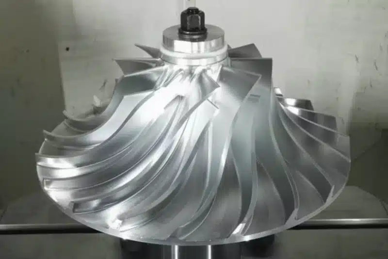
Multi-Port Housings
Flanges, bores and mounting features on different faces need a shared reference system. Fixed-angle 3+2 operations may suit these features; continuous five-axis motion is considered where the surface or access requires it.
Include in your enquiry: port sizes, sealing faces, hole locations, datum references and deburring requirements at intersecting passages.
Review Your Housing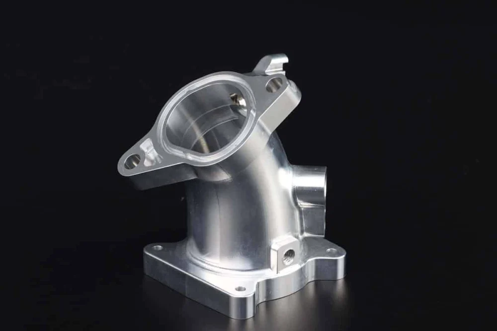
Starting Your 5-Axis Machining Order
What should I send for a quotation?
Send your 3D model and latest 2D drawing, with material and condition, quantities, finishes, critical tolerances and required production date. Include any inspection or documentation requirements and the delivery destination.
Do you offer simultaneous 5-axis machining or 3+2?
Both. PTSMAKE focuses on simultaneous 5-axis machining and also offers 3+2 positioning. We review which operations need continuous tool-axis movement and which can use a fixed cutting orientation.
Can you achieve ±0.005 mm tolerances?
Dimensional tolerances as tight as ±0.005 mm are possible on suitable features, subject to drawing and material review. The feature size, geometry and final processing matter. Position, profile, form and surface roughness need their own requirements.
Can you make a prototype before a larger order?
Yes. Send the prototype quantity and expected follow-on quantities together. We can review the initial part and the requirements that need to carry into repeat production.
How soon can production be completed?
Production ranges are 1–3 days for urgent prototypes, 7–15 days for small batches and 15–30 days for production runs. Final timing is confirmed with your quote after reviewing the part, material, quantity, finish and inspection requirements.
What inspection records can I request?
Tell us which features must be reported and whether you need material documentation, dimensional results or a first-article format. Agree the available records, measurement methods and sampling before ordering.
A Buyer’s Guide to 5-Axis CNC Machining
Understand the decisions behind a complex part: the machining route, tool access, critical tolerances, surface inspection and the cost of moving from a prototype to repeat orders.
1. When Does Your Part Need Simultaneous 5-Axis Machining?
Simultaneous 5-axis machining is useful when the cutting direction needs to change continuously as the tool follows a surface. With 3+2 machining, the rotary axes first orient the part or tool, then stay at that orientation during a three-axis cutting operation. The right choice depends on the features being machined; one part can use both approaches.
Consider a contoured component with mounting holes on angled faces. A continuously changing tool orientation may help finish its curved region or maintain clearance around neighboring features. The mounting holes may be better machined at fixed orientations. Calling the complete part “5-axis” does not mean every hole, roughing pass or finishing operation needs simultaneous motion.
| Feature to evaluate | Rota para discutir |
|---|---|
| Several flat faces and angled holes | 3+2 positioning with controlled access to each face |
| Curves requiring changing tool orientation | Simultaneous 5-axis finishing |
| Simple, readily accessible geometry | Whether a simpler milling route meets the drawing |
PTSMAKE focuses on simultaneous 5-axis machining and also provides 3+2 capability. Send the complete model so the route can be reviewed feature by feature. Useful questions include which surfaces need continuous motion, where fixed orientations are sufficient, and what remains inaccessible. For general milling requirements, see our CNC Milling capabilities.
2. Can Every Feature Be Finished in One Setup?
Five-axis access can reduce the number of times a part is repositioned, but it does not make every surface available in one clamping. The area held by a vise, fixture or mounting feature may still need another operation. Other limits include the space around the part, the rotary travel and the full cutting-tool assembly.
Tool access involves more than placing the cutter tip on the model. The shank and holder must clear surrounding walls and the fixture throughout the move. A position that looks possible in a static CAD view may become obstructed while the part tilts. The stock and holding arrangement also occupy space that is absent from the finished-part model.
For example, a multi-sided housing may allow its angled ports and upper faces to share one setup while the clamped base is finished later. Discuss which relationships matter between that base and the other features, how they will be recovered after reclamping, and where inspection will check them. A second operation can be a sensible part of a controlled route.
Ask what is covered by toolpath and machine-motion verification: the cutter, holder, stock, fixture and rotary travel. Also ask how the posted machine program is verified. A simulation of the cutter alone does not show every possible machine or fixture interference.
- Identify surfaces that must remain free of holding marks.
- Show whether temporary locating or clamping features are acceptable.
- Include nearby walls and all internal features in the model.
- Confirm the proposed route for surfaces hidden by the fixture.
Fully enclosed internal passages need a separate manufacturing assessment. More machine axes do not create a physical path through solid material. Evaluate the whole part and its workholding before committing to a one-setup requirement.
3. What Determines Accuracy Across Angled Faces?
Accuracy depends on the required characteristic and the complete machining and measurement plan. Reducing reclamping can help preserve relationships between features. Rotary-axis alignment, tool condition, cutting forces and workholding still affect the result. The number of axes is not a tolerance specification.
PTSMAKE offers dimensional tolerances as tight as ±0.005 mm on suitable features, subject to drawing and material review. This is a conditional dimensional capability. Surface profile, hole position, angularity and other geometric requirements must be specified and reviewed separately.
| Requisito | What the drawing should establish |
|---|---|
| A precision bore | Size limits and any separate form requirements |
| An angled mounting-hole pattern | Location and orientation relative to the specified datums |
| A functional curved surface | Profile control and the applicable reference requirements |
Imagine a bracket that locates on a bottom face and two mounting features. An angled bore can meet its diameter tolerance while its axis is incorrectly positioned relative to those locating features. Checking diameter alone would miss the assembly problem. Make the intended relationship clear through the drawing’s datum scheme and geometric controls.
Before production, identify the critical characteristics, their final material and finishing state, and the method of verification. If a tight requirement covers only a short bearing seat or selected surface, mark that extent clearly. This lets the machining and inspection effort follow the actual function of the part.
Have curved surfaces, angled bores or tight cross-face requirements?
Get your 5-axis machining quote4. How Should Curved Surfaces and Surface Finish Be Inspected?
Define the shape requirement and the surface-texture requirement separately. Surface profile evaluates deviation from the specified geometry. Roughness describes smaller-scale texture using parameters such as Ra. A smooth-looking curve can be the wrong shape, while a correctly shaped surface can still have unsuitable machining texture.
For a functional curve, provide the controlled model and drawing revision, the surface region to evaluate and the applicable tolerance. Follow the drawing’s datum references where specified. A profile control without datum references may address form alone; adding datum references can also constrain orientation and location. The inspection alignment must match the actual requirement.
Measurement planning should consider coverage across the surface, probe or sensor access, and how the part is supported. Checking a few convenient points may miss a local deviation between them. The appropriate sampling or scanning approach depends on the geometry and acceptance criteria, rather than on the label “CMM inspected.” KEYENCE’s surface-profile measurement guide explains relevant measurement considerations.
For example, a curved mating insert may need profile verification over its contact region and a separate roughness check there. Its non-contact relief surfaces may have different requirements. Mark those zones instead of applying the strictest finish to every visible face.
Agree the report contents before ordering: characteristic identifiers, specified limits, measured results and the condition in which the part is checked. For coated or polished parts, clarify which requirements apply after finishing. A report should make the acceptance decision traceable to the drawing.
5. When Can 5-Axis Machining Reduce Total Part Cost?
Five-axis machining can be economical when improved access and fewer setups remove enough work from the complete production route. Evaluate the total quoted part cost, including preparation, machining, finishing and inspection. A machine’s hourly rate alone cannot show whether it is the better choice.
A part with many angled faces may otherwise need several fixtures and repeated positioning. Five-axis access can simplify that route. Conversely, a readily accessible part may gain little from the additional programming and verification needed for a more complex strategy. The comparison should use the same drawing requirements and quantity.
| Cost area | Useful question for the quote |
|---|---|
| Preparação | What programming, fixture preparation and first-part work is included? |
| Each component | Which cutting, repositioning and finishing operations remain? |
| Acceptance | Which features and how many parts are measured? |
| Repeat orders | What must be reviewed again if quantity or revision changes? |
Request separate prices for the prototype quantity and the expected repeat batch. Preparation shared across a batch contributes differently to each piece than it does to a single prototype. Keep required documentation and finishing consistent between those comparisons.
Ask for design alternatives where they could meaningfully change the route: a more accessible recess, a less restrictive nonfunctional surface or a revised holding allowance. Keep the original drawing as the baseline and approve alternatives explicitly. A lower price is useful only when the resulting part still meets the application and agreed acceptance requirements.
6. Which Design Changes Improve Tool Access and Stability?
Start by making the required feature reachable with a stable tool and a secure holding arrangement. Tilting can help a shorter tool approach a deep or angled area, but it does not remove the rigidity limits of a slender tool or a flexible wall. Review clearance and support together.
A useful design review compares the present feature with a functionally acceptable alternative. For a deep pocket, discuss whether its opening or internal radius can increase enough to improve the proposed tool assembly. For a tall wall, identify where stiffness is essential and whether adjacent material can provide support during machining. Neither change should be made without design approval.
- Internal corners: allow a practical cutter radius where the mating geometry permits.
- Deep recesses: remove unnecessary depth and review clearance for the holder as well as the cutting edge.
- Thin walls: discuss support, clamping locations and the sequence for removing surrounding material.
- Complex outer shapes: preserve a useful locating or holding area when the application allows it.
As a design example, an angled pocket beside a tall rib may be difficult because the holder approaches the rib before the cutter reaches the pocket floor. Changing the pocket opening could help; simply selecting a longer tool introduces a different stability problem. Review the actual obstruction before changing a dimension.
There is no single minimum wall thickness or maximum pocket ratio that covers every material and shape. Send the complete model and explain which features are functional, so DFM suggestions can address the real constraints.
Send the model, critical requirements and order quantity for a part-specific review.
Discuss your 5-axis part7. How Do Material Condition and Finishing Affect the Result?
Specify the material grade and condition together with the final surface requirements. Five-axis access expands the machining options, but the part must still satisfy its strength, stiffness, temperature, corrosion and assembly needs. A broad label such as “aluminum” or “stainless steel” is not a complete material specification.
For a complex lightweight component, separate the requirements of thin walls, mounting features and contoured working surfaces. Ask whether the proposed material condition and machining sequence suit each region. If heat treatment is required, include its condition or specification and discuss which dimensional requirements must be achieved afterward. Treat it as part of the material and manufacturing route.
Finishing also needs a feature-by-feature review. On anodized aluminum, the oxide forms partly within the original surface and partly outward. Coating thickness is therefore not the same as outward dimensional growth. The guia de referência do Conselho de Anodizadores de Alumínio explains this distinction; the allowance for a particular part must follow the agreed process.
Consider an anodized curved housing with precision locating bores. Decide whether those bores are coated, masked or finished by an agreed subsequent operation. Define the condition in which the bore size and relevant surface profile will be accepted. An appearance instruction such as “black anodized” does not answer those questions.
Mark cosmetic surfaces, functional contact areas and any restricted treatment zones on the drawing. If polishing is requested, identify which geometry must be preserved. Material substitutions or finishing changes should be reviewed against the complete specification and approved before production.
8. What Should an RFQ Include for Prototypes and Repeat Orders?
Send matching 3D geometry and a controlled drawing that explains how the part will be accepted. Include the part number and revision, material grade and condition, quantity, finishing requirements and target date. Identify critical features and the records needed with the order. Resolve differences between the model and drawing before production.
- Geometry: the complete model, including internal features and neighboring surfaces that constrain access.
- Aceitação: dimensions, geometric controls, datums, surface requirements and final inspection state.
- Escopo do pedido: prototype quantity, expected repeat batches and requested inspection or material documentation.
- Schedule: the required date and any separate milestone for first-part approval.
PTSMAKE’s production lead times are 1–3 days for urgent prototypes, 7–15 days for small batches and 15–30 days for production runs. Final lead time is confirmed with your quote, based on the part, material, quantity and finish. Include special inspection requirements early so the agreed schedule covers the work needed for acceptance.
For repeat production, use the first part to check the agreed characteristics and assembly needs. One acceptable sample does not establish long-term process capability. NIST’s process-capability guidance explains why stability and appropriate data matter.
Before reordering, confirm the revision and document any approved deviation or design change. Agree the inspection scope for the next batch rather than assuming the prototype report automatically defines it. This gives both teams a clear basis for comparing quotes, reviewing results and handling later changes. For parts involving several machining processes, start with our CNC Machining capabilities.
Get Your 5-Axis CNC Machining Quote
Share the model, drawing, material and quantities. We will review the geometry, critical features and production requirements with you.