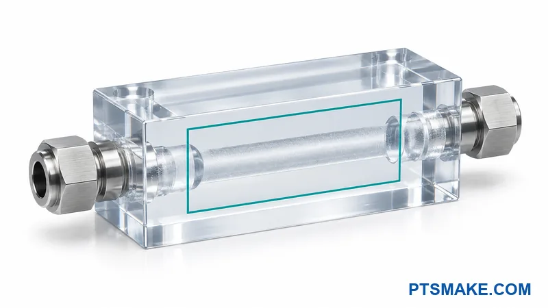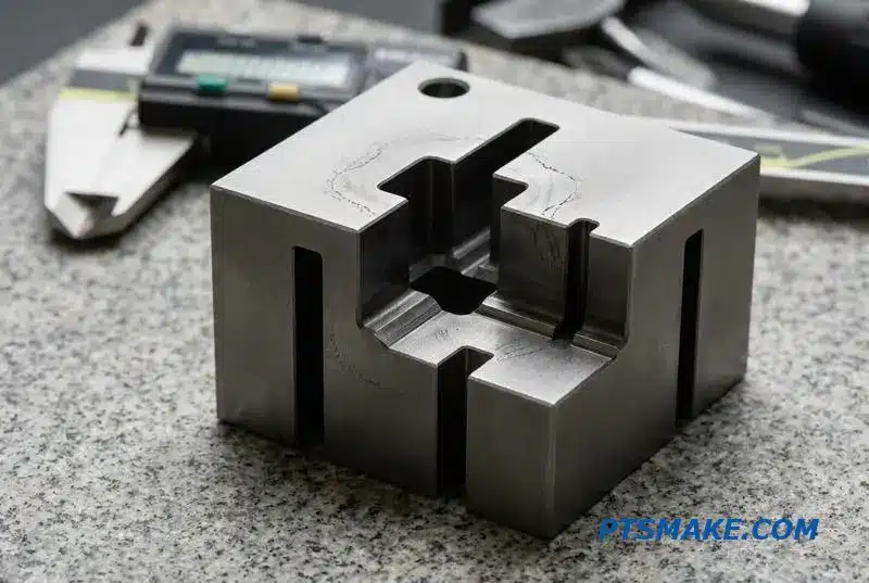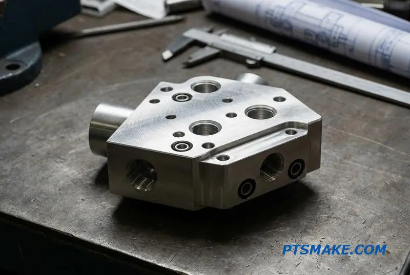

Sourcing CNC machined valve bodies for liquid cooling that pass leak tests on the first try is harder than it looks. One ovality issue on a ball bore, one burr in a cross-drilled port, and your entire CDU build slips.
Liquid cooling valve bodies need CNC machining with bore tolerances of ±0.05mm, seat finishes down to Ra 0.2µm, and full leak testing at 1.5× rated pressure. Material choice (316L, brass, 6061-T6) depends on coolant chemistry and galvanic pairing.
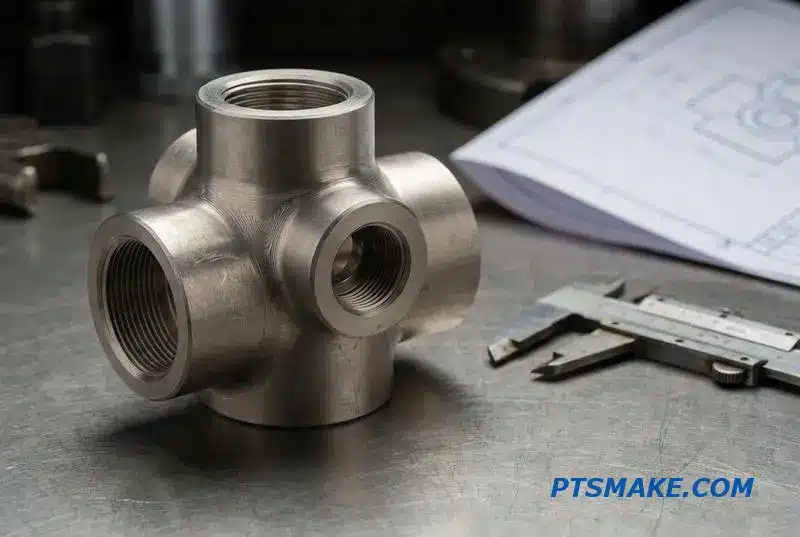
In this guide, I will walk you through the materials, tolerances, surface finishes, and testing methods I use at PTSMAKE when machining valve bodies for data center cooling loops. Each section gives you the specs and decisions that drive part reliability.
Why Liquid Cooling Valves Depend on Precision CNC Machining
The market for data center liquid cooling valves is growing rapidly, projected to expand significantly by 2032. This growth highlights a critical fact: every valve in these systems relies on a precisely manufactured foundation. The valve body is that foundation, crafted almost exclusively through CNC machining.
The Unseen Core of Reliability
Every ball, check, or pressure relief valve contains a body with complex internal passages and sealing surfaces. These features must be machined to incredibly tight tolerances. Any deviation can lead to leaks, which are catastrophic in a data center environment. Reliable, long-term operation is impossible without this precision.
Key Machining Demands
Different valves require specific machining focuses to function correctly. A slight error in manufacturing directly translates to system failure.
| Valve Type | Primary Machining Focus | Consequence of Failure |
|---|---|---|
| Ball Valve | Spherical Sealing Surfaces | Catastrophic Leak |
| Check Valve | Internal Seat Geometry | Backflow, System Damage |
| Relief Valve | Spring Seat & Orifice | Over-pressurization |
This is why CNC machined fittings and valves for liquid cooling are the industry standard; no other process offers this level of control.
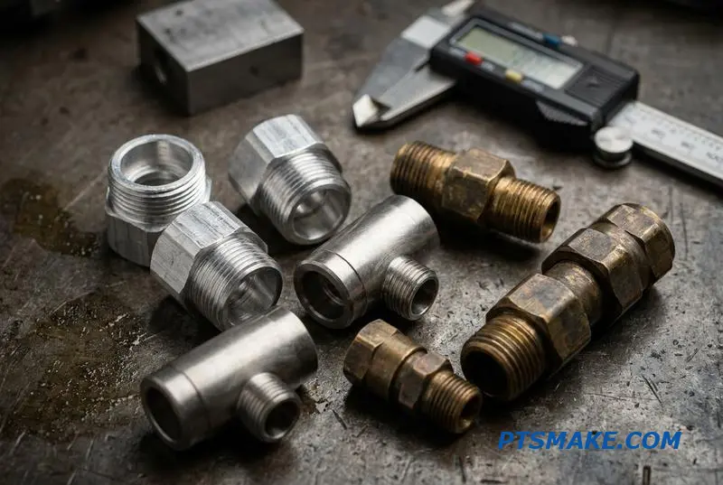
The success of a CNC machined valve body goes beyond just holding tight tolerances. The entire manufacturing approach, from material selection to final surface treatment, plays a crucial role in the valve’s performance and lifespan. It’s a process of balancing multiple engineering requirements.
Critical Manufacturing Considerations
Choosing the right material is the first major decision. Brass offers excellent machinability and cost-effectiveness for general applications. For systems with aggressive coolants, stainless steel provides superior corrosion resistance. Aluminum is often selected for its light weight and excellent thermal conductivity.
| Material | Key Advantage | Common Application |
|---|---|---|
| Brass (C360) | Cost-Effective, Good Machinability | General Purpose Cooling |
| Stainless Steel (316) | Superior Corrosion Resistance | High-Purity/Aggressive Fluids |
| Aluminum (6061) | Lightweight, High Thermal Conductivity | Performance-Critical Systems |
Surface Finish: More Than Aesthetics
The surface finish inside the valve body directly affects fluid dynamics. A smoother surface reduces turbulence and pressure drop, improving the overall efficiency of the cooling loop. Achieving a near-Isotropic1 finish within complex internal geometries is a challenge that distinguishes expert liquid cooling valve manufacturing.
The growth in liquid cooling places immense pressure on component quality. Precision CNC machining is the foundational technology ensuring valve bodies are reliable and leak-free. Mastering material selection, tight tolerances, and advanced surface finishes is essential for meeting the demands of modern high-performance systems.
The Valve Body in a Liquid Cooling System: Where It Fits and What It Does
The valve body is the unsung hero in any liquid cooling system. It acts as the traffic controller for the coolant, ensuring it flows precisely where needed. Without a properly designed and machined valve body, the entire system’s efficiency and reliability would collapse.
Critical Roles of a Valve Body
Different valves perform distinct tasks, from simple on/off control to intricate flow modulation. The body houses these mechanisms and must withstand constant pressure and temperature fluctuations. This makes high-quality manufacturing essential for performance.
Core Functions Overview
| Valve Type | Primary Function | Typical Location |
|---|---|---|
| Ball Valve | On/Off Isolation | CDU Inlet, Rack Manifold |
| Proportional Valve | Flow Modulation | To Cold Plates |
| Check Valve | Prevent Backflow | Parallel Coolant Lines |
| Relief Valve | Overpressure Safety | System High-Point |
Understanding these roles is the first step in appreciating the complex engineering behind these critical components. The manufacturing process must be flawless.
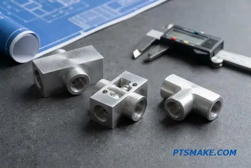
Mapping Valves in a Cooling Loop
In a data center liquid cooling loop, specific valves are placed strategically. Ball valves, for instance, are used at the Coolant Distribution Unit (CDU) inlets and rack connections. Their job is simple: provide a reliable way to isolate sections for maintenance without draining the entire system.
Precision Flow Management
Proportional control valves are more sophisticated. They sit just before the individual cold plates, modulating coolant flow based on the real-time thermal load of the processors. This ensures each component gets the exact cooling it needs without wasting pumping energy. Check valves are often placed in parallel branches to prevent reverse flow.
Shared Machining Challenges
While their functions vary, the manufacturing demands for these valve bodies overlap significantly. The integrity of the entire cooling system depends on the precision of these parts. Problems like Cavitation2 can arise from poorly designed internal geometries.
From Function to Fabrication
Every valve body, regardless of type, presents similar challenges that require expert CNC machining. These challenges are foundational to creating reliable CNC Machined Fittings and Valves for Liquid Cooling.
| Machining Process | Critical Requirement | Impact on Performance |
|---|---|---|
| Internal Port Drilling | Smooth, precise passages | Prevents pressure drops and turbulence |
| Sealing Surface Finishing | Extremely low surface roughness | Ensures a leak-proof seal with gaskets |
| Thread Cutting | Accurate pitch and depth | Guarantees secure, leak-free connections |
| Pressure Testing | Material integrity verification | Confirms the body can handle system pressure |
At PTSMAKE, we focus on mastering these processes to deliver components that meet the highest standards for performance and reliability.
Valve bodies perform diverse roles, from simple isolation to precise flow control. However, they all share common and demanding manufacturing requirements. Precision in porting, sealing surfaces, and thread cutting is absolutely critical for system integrity and preventing leaks in any high-performance cooling application.
Material Selection for Liquid Cooling Valve Bodies
Choosing the right material for liquid cooling valve bodies is critical. This decision directly impacts system reliability, longevity, and overall cost. The wrong choice can lead to leaks, corrosion, and premature failure, compromising the entire cooling loop. We need to balance three key factors carefully.
Key Decision Factors
Coolant compatibility, corrosion resistance, and machinability are the primary considerations. Each material offers a unique combination of these properties. For instance, a highly corrosion-resistant alloy might be difficult to machine, increasing the cost of your CNC machined fittings and valves for liquid cooling.
Material Trade-Offs at a Glance
Understanding the basic trade-offs is a good starting point. My team at PTSMAKE often uses a simple comparison to help clients visualize how these factors interact.
| Material | Corrosion Resistance | Machinability | Relative Cost |
|---|---|---|---|
| 316L Stainless Steel | Excellent | Fair | High |
| 303 Stainless Steel | Good | Good | Medium |
| Brass C36000 | Fair | Excellent | Low |
| Aluminum 6061-T6 | Poor (needs coating) | Good | Low |
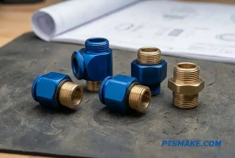
When diving deeper into valve body material selection, the specific grade of metal becomes essential. Each alloy has distinct characteristics that make it suitable for certain applications. It is not just about choosing stainless steel; it is about choosing the right stainless steel.
Stainless Steel Options
316L Stainless Steel
For water-glycol loops, I often recommend 316L stainless steel. Its corrosion resistance is excellent, which is vital for system integrity. However, it work-hardens during machining, so we must use sharp tooling and controlled feed rates to achieve the required precision without driving up costs.
303 Stainless Steel
If the application is less critical, 303 stainless offers a good balance. It is much easier to machine than 316L, which can lower part cost. However, its corrosion resistance is lower, making it less ideal for aggressive coolants or demanding environments.
Brass and Aluminum Considerations
Brass C36000 machines beautifully and is cost-effective for lower-pressure systems. The main drawback is the risk of galvanic corrosion3 when it is in contact with aluminum components like cold plates. This is a common failure point I’ve seen in poorly designed mixed-metal loops.
Aluminum 6061-T6 is lightweight and affordable, making it a great option for components on the CDU side. It requires a protective coating, such as hard anodizing, to prevent corrosion. For mixed-metal loops, electroless nickel plating provides excellent protection for stainless or copper parts.
Choosing the right material is a balance of performance, machinability, and cost. Stainless steel offers superior corrosion resistance, while brass provides excellent machinability. Each choice has direct consequences for the final product’s reliability and budget, making this a critical decision in any liquid cooling design.
Ball Valve Body Machining: The Most Common Cooling Valve
Precision in ball valve body CNC machining is non-negotiable. The process centers on creating a perfect housing for the ball and seats. Any deviation can compromise the entire liquid cooling system. Key features require distinct machining operations, each with its own critical tolerances.
Core Machined Features
The main bore, which houses the ball, is the most critical element. We also machine precise end connections, such as NPT or BSPP threads, for system integration. Additionally, the stem hole and any flange faces must be perfectly aligned.
Typical Tolerances
Based on our testing, maintaining strict tolerances is essential for performance. Here are some common specifications we work with at PTSMAKE for CNC machined fittings and valves for liquid cooling.
| Feature | Typical Tolerance | Critical Function |
|---|---|---|
| Main Bore Diameter | ±0.05 mm | Sealing & Ball Rotation |
| End Connection Threads | Class 2A/2B | Leak-Proof Connection |
| Stem Hole Position | ±0.1 mm | Actuator Alignment |
| Sealing Face Flatness | 0.02 mm | Gasket Sealing |
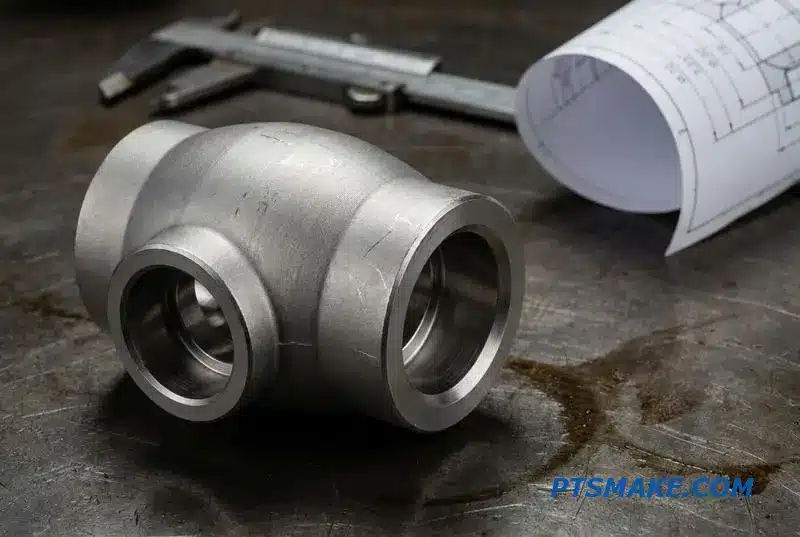
The most significant challenge in stainless steel ball valve manufacturing is maintaining the spherical geometry of the main bore. Any ovality, even microscopic, creates a path for leakage. This is why the ball-and-seat sealing mechanism depends entirely on the bore’s geometric integrity.
Machining Strategies
Two primary strategies exist: a two-setup approach or a single-setup process. The two-setup method involves machining the bore and one end, then re-fixturing to complete the opposite end. While common, it risks introducing alignment errors between the setups.
At PTSMAKE, we often prefer a single-setup on a multi-axis lathe with live tooling. This method machines all features in one clamping, ensuring superior Concentricity4 between all features. This is crucial for high-performance applications.
Material and Finish Considerations
Material choice depends on the application. We typically use 316L stainless steel for coolant-facing components due to its corrosion resistance. For facility-side parts, brass is a cost-effective alternative. A surface finish of Ra 0.8µm is standard on sealing faces to ensure a reliable seal.
| Aspect | Specification | Rationale |
|---|---|---|
| Material (Coolant Side) | 316L Stainless Steel | Corrosion Resistance |
| Material (Facility Side) | Brass (e.g., C360) | Cost-Effectiveness |
| Sealing Surface Finish | Ra 0.8 µm | Prevents Micro-Leaks |
Successful ball valve body CNC machining relies on precise bore geometry, strategic fixturing, and proper material selection. Achieving tight tolerances, especially concentricity, is essential to prevent leaks and ensure reliable performance in demanding liquid cooling applications.
Proportional Control Valve Bodies: Internal Passages and Porting
Proportional control valves are among the most complex components in liquid cooling systems. Their purpose is dynamic flow modulation, which requires incredibly intricate internal porting. It’s not just about drilling holes; it’s about creating precise pathways for fluid.
Key Internal Features
The inlet and outlet ports must be machined at specific angles. Inside, metering edges are carefully shaped to control flow rates with high accuracy. The entire design is engineered for precise performance and long-term reliability in demanding applications.
The Spool Bore
The clearance between the spool and its bore is critical for function. We machine these features to a tight H6/g6 fit, ensuring smooth, responsive action without leakage.
| Feature | Standard Tolerance | Machining Impact |
|---|---|---|
| Spool Bore Diameter | ±0.01mm | Requires precision boring/honing |
| Port Angle | ±0.5 degrees | Needs multi-axis CNC capability |
| Metering Edge | Sharp, burr-free | Demands specialized deburring tools |
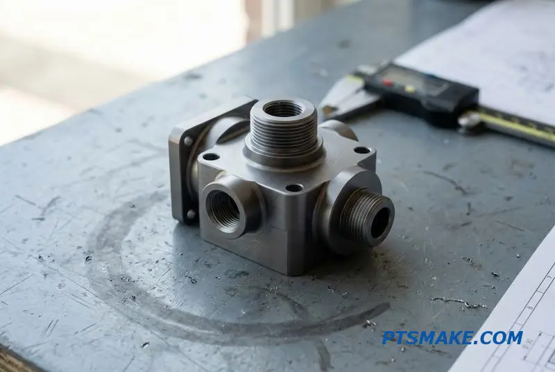
Machining Intricate Geometries
The process of control valve body manufacturing CNC from solid block is a significant challenge. It involves much more than basic milling. Cross-hole drilling for port intersections must be perfectly aligned to avoid flow disruption and pressure drops.
Deburring and Surface Finish
Any burrs left on internal edges after drilling can create turbulence and affect flow. We use advanced deburring to ensure smooth fluid dynamics. The spool bore requires a fine surface finish, typically Ra 0.4µm, to prevent stiction5 and premature wear, ensuring the valve responds instantly.
Manufacturing Approaches
Proportional valve body machining offers two primary paths. Machining from a solid billet provides superior material integrity and strength. In contrast, investment casting followed by finish machining can reduce initial costs but may risk material defects like porosity.
| Method | Advantages | Disadvantages |
|---|---|---|
| Machined-from-Solid | High strength, no porosity | Higher material waste, longer cycle time |
| Investment Casting | Less material waste, near-net shape | Potential porosity, requires secondary machining |
At PTSMAKE, our 4-axis and 5-axis milling centers are ideal for creating these complex multi-port bodies directly from solid materials.
Manufacturing proportional control valve bodies demands advanced CNC capabilities. Precision is vital for internal porting, tight tolerances, and superior surface finishes. The right approach—whether machined-from-solid or cast—directly impacts the valve’s performance and reliability in critical liquid cooling systems.
Check Valve Bodies: Spring Retention and Seat Geometry
In liquid cooling, check valves are essential for preventing backflow when a pump shuts down. The body is the foundation. Its machining demands high precision for features like the internal bore, which guides the poppet, and the valve seat.
Key Machining Features
The valve seat is the most critical element. It’s often a 45-degree bevel machined directly into the body or a pocket designed for a soft-seat insert. Precise spring retention features are also machined to control the valve’s cracking pressure reliably.
Seat Geometry Comparison
This table outlines the common seat types we machine for CNC Machined Fittings and Valves for Liquid Cooling.
| Seat Type | Material | Key Advantage | Common Application |
|---|---|---|---|
| Beveled Seat | Same as body (e.g., 316L) | Durability | High-pressure systems |
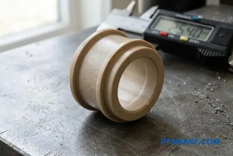
| Soft-Seat Insert | PEEK / PTFE | Superior sealing | Low-pressure, critical seal |
The main challenge in check valve body CNC machining is the concentricity between the valve seat and the internal bore. If these two features are not perfectly aligned, the poppet or disc will not seal correctly, leading to leaks and system failure.
Achieving Sealing Integrity
We consistently hold a tolerance of ±0.05mm Total Indicated Runout6 (TIR) between the seat and bore. This isn’t just a number; it’s a requirement for reliable performance. Any deviation beyond this can cause uneven wear and compromise the seal, a critical failure in liquid cooling for sensitive electronics.
Material and Machining Synergy
For the body, 316L stainless steel is a common choice due to its corrosion resistance. When a design calls for a soft seat, we machine a precise pocket for a PEEK or PTFE insert. Controlling the depth of the spring pocket is equally important, as it directly influences the force required to open the valve.
| Parameter | Specification | Verification Method |
|---|---|---|
| Seat-to-Bore Concentricity | ±0.05mm TIR | CMM Probe Scan |
| Spring Pocket Depth | ±0.1mm | Digital Depth Gauge |
| Sealing Surface Finish | Ra 0.8 µm or better | Surface Profilometer |
At PTSMAKE, we use CMM verification on every batch to ensure this concentricity is met. This commitment to one-way valve machining precision prevents costly field failures for our clients.
Ultimately, successful check valve function hinges on precise machining of the body. The concentricity between the seat and bore, coupled with proper material selection and verification, ensures reliable backflow prevention in demanding liquid cooling applications.
Pressure Relief Valve Bodies: Threading, Seat Angle, and Set-Pressure Accuracy
The performance of a pressure relief valve (PRV) is defined by the machining precision of its body. The internal geometry, especially the valve seat, directly controls set pressure accuracy. Even minor deviations can lead to catastrophic failure or persistent, costly leaks in a system.
Key Machined Geometries
The valve body contains several critical features. These include the nozzle or seat, the spring chamber, adjustment screw threads, and the outlet port. Each element must be machined to tight specifications to work in concert, ensuring reliable and repeatable valve operation under pressure.
From Blueprint to Performance
The relationship between the blueprint and the final product’s performance is direct. For instance, the angle and surface finish of the seat determine how effectively the valve seals and opens at the precise set pressure. It’s a game of microns.
| Feature | Machining Focus |
|---|---|
| Valve Seat | Angle, width, and surface finish |
| Spring Chamber | Internal diameter and depth |
| Adjustment Threads | Pitch diameter and thread class |
| Outlet Port | Bore concentricity and diameter |
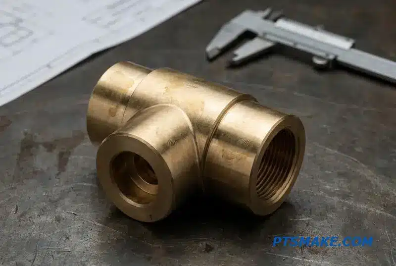
When we approach pressure relief valve body CNC machining, we treat tolerances as absolute rules, not guidelines. The connection between machining precision and set-pressure repeatability is unbreakable. Poor geometry or surface finish is the primary cause of premature blow-off or slow seat leakage.
Critical Tolerances and Finishes
For metal-to-metal seats requiring a bubble-tight shut-off, a surface finish of Ra 0.2µm is often necessary. Based on our tests, anything rougher introduces a leak path. Seat width tolerance is typically held to ±0.025mm to ensure the force from the spring is applied consistently.
The Role of Threads and Concentricity
The adjustment screw threads, usually a Class 2A/2B fit, allow for fine-tuning of the set pressure. Poor thread geometry can introduce friction or backlash, making accurate adjustment impossible. Equally important is the concentricity between the seat and the guide bore, which prevents uneven loading and premature wear. Poor control here can increase performance Hysteresis7.
These principles are especially critical in systems like CNC Machined Fittings and Valves for Liquid Cooling, where reliability is paramount.
Achieving accurate set-pressure and a bubble-tight seal in a PRV relies entirely on the CNC machining of the valve body. Key factors include seat geometry, surface finish (Ra 0.2µm), and tight tolerances on features like threads and bore concentricity.
Multi-Axis CNC Machining for Complex Valve Body Geometries
Deciding between 3-axis and 5-axis machining is a critical step. For complex valve bodies, especially those in liquid cooling systems, multi-axis machining often becomes a necessity, not a luxury. It allows for creating intricate features in a single setup.
When is 5-Axis Essential?
For components with ports on multiple, non-orthogonal faces, 5-axis is the clear winner. This approach, which we frequently use at PTSMAKE, simplifies the process for parts requiring undercuts or back-facing operations that are impossible to reach with a 3-axis machine in a single clamping.
Key Decision Factors
| Feature Complexity | 3-Axis Approach | 5-Axis Solution |
|---|---|---|
| Compound-Angle Ports | Multiple complex fixtures | Single setup, higher accuracy |
| Undercuts/Back-facing | Special tooling, multiple setups | Direct machining access |
| High Concentricity | Risk of tolerance stacking | Maintained in one operation |
The "One-Hit" Machining Strategy
The primary advantage of 5-axis valve body CNC is the "one-hit" strategy. Completing a part in a single setup drastically reduces the risk of errors introduced by re-fixturing. This is vital for maintaining tight tolerances between features on different faces of the part.
We’ve seen that for CNC machined fittings and valves for liquid cooling with four or more angled ports, this approach is more cost-effective. The higher hourly rate of the machine is offset by eliminating the need for multiple custom fixtures and the associated labor costs for setups.
Comparing Manufacturing Approaches
Choosing the right process directly impacts the final cost and quality. It’s a trade-off between machine time, labor, and tooling investment.
Cost and Time Breakdown
Multi-axis machining valve manufacturing requires a deeper analysis than just comparing machine hour rates. After reviewing several projects, our data shows a clear pattern.
| Metric | 3-Axis + Multiple Setups | 5-Axis Single Setup |
|---|---|---|
| Cycle Time | Higher (includes setup time) | Lower (continuous machining) |
| Accuracy | Lower (tolerance stack-up) | Higher (single reference frame) |
| Fixturing Cost | High (multiple custom jigs) | Minimal (standard vise/chuck) |
| Labor Cost | High (multiple setups) | Lower (less operator intervention) |
The use of advanced functions like Tool Center Point Control (TCPC)8 on our 5-axis machines allows the tool tip to follow a programmed path regardless of the tool’s length or the machine’s rotary axis movements. This ensures superior accuracy on complex curved surfaces and angled holes.
Multi-axis machining is essential for complex valve bodies, improving accuracy and reducing total project costs. By minimizing setups through a "one-hit" strategy, it overcomes the higher hourly rate, delivering a superior and more economical part in the end.
Swiss-Type Turning for Small Valve Components: Valve Cores and Inserts
Why Swiss Turning for Intricate Valve Parts?
For small, complex valve components, conventional lathes often fall short. Parts like valve stems and poppets demand a level of precision that is difficult to achieve when workpiece deflection becomes an issue. This is where Swiss-type turning provides a distinct advantage for us at PTSMAKE.
Swiss CNC turning valve parts is ideal for components with diameters from 3mm to 20mm and lengths up to 200mm. By supporting the stock right at the cutting tool, the machine minimizes vibration and deflection, ensuring exceptional straightness and concentricity on long, slender parts.
Key Components We Machine
Precision valve insert machining is a core part of our work. We handle various secondary components, each with its own unique challenges. Swiss turning allows us to consistently meet these demands for applications like CNC machined fittings and valves for liquid cooling.
| Component | Common Machining Challenge |
|---|---|
| Valve Stems | Maintaining straightness over long lengths |
| Poppets | Achieving critical sealing surface finishes |
| Metering Pins | Taper accuracy and fine-point geometry |
| Seat Inserts | Concentricity between bore and seat |
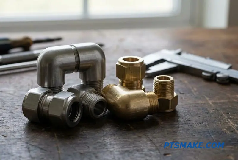
The Technical Edge of Swiss Machining
The superiority of Swiss-type machines for these parts comes down to three key features. These technologies allow us to machine a component completely in a single setup, which is crucial for both precision and efficiency in producing parts for liquid cooling systems.
Guide Bushing for Stability
The guide bushing is the cornerstone of Swiss turning. It provides rigid support to the workpiece right next to the cutting tools. This setup virtually eliminates deflection on long, slender parts, ensuring uniform diameters and superior surface finishes from end to end.
Sub-Spindle for Complete Machining
After the main spindle completes its operations, the sub-spindle picks up the part. This allows us to machine the back end without manual intervention. This process guarantees excellent concentricity between features on opposite ends of the component, a critical factor for valve performance.
Live Tooling for Complex Features
Our Swiss machines are equipped with live tooling. This enables us to perform secondary operations like cross-drilling, slotting, and milling flats in the same cycle. This integrated approach reduces lead times and improves the accuracy of features relative to the turned diameters.
Material and Precision Standards
We work with a range of materials selected for their performance in demanding valve applications. The heat treatment of 17-4PH, known as Precipitation hardening9, is critical for achieving high wear resistance. Based on our tests, we consistently hold tight tolerances.
| Material | Primary Application |
|---|---|
| 303/316L SS | Corrosion resistance and general use |
| 17-4PH H900 | High-pressure, high-wear components |
| PEEK | Electrical insulation and chemical resistance |
We achieve tolerances of ±0.01mm on diameters and surface finishes as fine as Ra 0.4µm on critical sealing surfaces.
Swiss-type turning is indispensable for producing small, complex valve components with high precision. Its ability to manage long, slender parts and complete features in one setup makes it ideal for valve cores, inserts, and other intricate parts requiring tight tolerances.
Threading and End Connections in Valve Body Machining
Proper threading is essential for creating pressure-tight, reliable connections in valve bodies. It’s not just about cutting grooves; it’s about selecting the right standard and executing it with precision. Each thread type serves a specific purpose, from tapered to straight profiles.
Key Thread Standards
Different applications demand different thread standards. For CNC machined fittings and valves for liquid cooling, understanding these is fundamental. In our work at PTSMAKE, we commonly machine these primary types, each with unique geometric requirements for sealing and mechanical engagement.
| Thread Type | Sealing Method | Common Application |
|---|---|---|
| NPT/BSPT | Thread Interference (Taper) | General purpose, pressure lines |
| UN/UNF/BSPP | Gasket or O-ring | Fittings, hydraulic connections |
| SAE ORB | O-ring in a Groove | High-pressure hydraulic systems |
Importance of Precision
Achieving a perfect seal begins with precise machining. In valve body thread machining, even minor deviations in pitch, angle, or depth can lead to leaks or connection failure under pressure. This precision is what separates a reliable component from a liability.
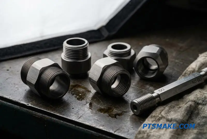
Gaging and Quality Control
Verifying thread geometry is as critical as cutting it. We use specific gages for each thread type. For instance, NPT threads require L1 and L2 plug gages to check taper depth, ensuring proper thread engagement without bottoming out or interference.
| Gage Type | Used For | Purpose |
|---|---|---|
| Ring Gage | External Threads | Go/No-Go check for pitch diameter |
| Plug Gage | Internal Threads | Go/No-Go check for pitch diameter |
| NPT L1/L2 Gage | Tapered Threads | Verifies proper engagement depth |
Thread Milling vs. Tapping
For larger diameter threads, I often recommend thread milling over tapping. Tapping can sometimes exert high torque, risking tool breakage or distorting the part. Thread milling, which uses Helical Interpolation10, offers a more controlled process.
This method often produces superior thread quality and surface finish. An added benefit is that a single tool can machine various thread sizes with the same pitch, offering flexibility in production, especially during NPT thread CNC turning operations.
Common Machining Pitfalls
Over-tapering NPT threads is a frequent issue that causes assembly interference. Another problem is damaged thread starts from improper tool entry, which can ruin the seal. Finally, burrs left on thread crests prevent proper seating and must be carefully removed.
Selecting the correct thread type, executing it with precision, and verifying it with the right gages are non-negotiable for high-performance valve bodies. Understanding common pitfalls and choosing the optimal machining method, such as thread milling for larger diameters, ensures a leak-proof and reliable connection.
Sealing Surface Machining: O-Ring Grooves, Flange Faces, and Metal Seats
In liquid cooling, the sealing surface is everything. A single microscopic flaw can lead to a catastrophic failure. Machining these surfaces on CNC fittings and valves is a task where precision isn’t just a goal; it’s the only acceptable outcome. There’s no room for error.
Key Sealing Methods
We primarily encounter three types of seals. Each has unique machining requirements that directly impact its performance. Understanding these distinctions is crucial for producing reliable components for liquid cooling systems.
| Seal Type | Primary Machining Focus | Common Application |
|---|---|---|
| O-Ring Groove | Groove Depth & Surface Finish | Static seals between body halves |
| Compression Seal | Surface Flatness & Finish | Gasket or ferrule connections |
| Metal-to-Metal Seat | Concentricity & Surface Finish | High-pressure ball valves |
O-Ring Groove Tolerances
For standard AS568 O-ring grooves, controlling the groove depth is critical. We hold a tolerance of ±0.05mm. The bottom surface finish must be Ra 1.6µm or better, with no tool marks running parallel to the potential leak path.
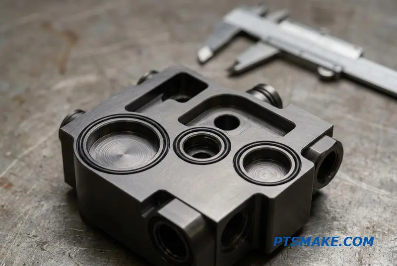
The success of CNC machined fittings and valves for liquid cooling hinges on achieving perfect sealing surfaces. Each design demands a specific approach, from the precise dimensions of an O-ring groove to the flawless finish of a metal-to-metal seat. Compromise is not an option.
Machining for O-Ring Glands
For O-ring grooves, the goal is controlled compression. A groove that is too deep fails to compress the O-ring sufficiently, creating a leak path. If it is too shallow, the O-ring is crushed, leading to premature failure. This is why the ±0.05mm depth tolerance is non-negotiable.
Metal-to-Metal Seat Requirements
Metal-to-metal seats are the most demanding. In a hard-seat ball valve, the seat must have a concentricity to the bore within ±0.025mm. The surface finish must be exceptionally smooth, typically between Ra 0.2µm and 0.4µm. This is where the principles of Tribology11 become critical.
Critical Geometric Controls
Achieving these specifications requires precise toolpath control and machine stability. The geometry, whether a 45-degree angle or a sharp edge, must be perfect to create a line of contact that holds high pressure without leaking.
| Feature | GD&T Control | Typical Specification |
|---|---|---|
| O-Ring Groove Bottom | Surface Profile | 0.05mm |
| Flange Face | Flatness | 0.02mm |
| Metal Seat Angle | Angularity | ±0.1° |
| Metal Seat to Bore | Concentricity | 0.025mm |
Machining sealing surfaces is a meticulous process. Success depends on hitting tight tolerances for groove depth, surface finish, and geometric controls like concentricity. These details determine the reliability of CNC machined fittings and valves in any liquid cooling application.
Leak Testing Machined Valve Bodies: Standards and Methods
Ensuring a valve body is leak-proof is non-negotiable, especially for CNC machined fittings and valves for liquid cooling. A minor flaw can lead to catastrophic system failure. At PTSMAKE, we rely on a structured approach to validate the integrity of every component we produce.
Key Leak Testing Protocols
Different tests target different potential failure points. Hydrostatic tests check the body’s structural strength, while pneumatic tests focus on the seal’s effectiveness. For the most critical applications, advanced methods are required.
Common Test Parameters
Here is a quick overview of the standard tests we employ for a typical liquid cooling valve pressure test.
| Test Method | Primary Purpose | Typical Pressure/Sensitivity |
|---|---|---|
| Hydrostatic Pressure | Body Integrity & Strength | 1.5× Rated Pressure (10-15 bar) |
| Pneumatic Seat Leakage | Seal Effectiveness | Low Pressure (0.5-1 bar) |
| Helium Mass Spectrometry | Hermetic Sealing | <1×10⁻⁶ mbar·L/s |
Applying the Right Test Method
Choosing the correct test is crucial for effective valve body leak testing. Each method provides different information about the part’s performance and is suited for specific stages of validation.
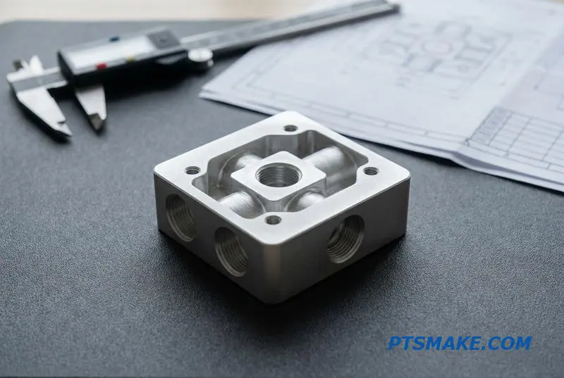
Hydrostatic Pressure Testing
We conduct this test to confirm the fundamental integrity of the valve body. By subjecting the part to 1.5 times its rated pressure, typically 10-15 bar, and holding it for 2-5 minutes, we verify there are no structural weaknesses, porosity, or cracks from the machining process.
Pneumatic Seat Leakage Testing
This test focuses on the valve seat’s ability to seal. Using low-pressure air at 0.5-1 bar, we check for leaks via a bubble test or by measuring differential pressure decay. I always recommend using dry nitrogen to prevent moisture contamination within the component.
Helium Mass Spectrometry12 for Ultimate Assurance
For hermetically sealed assemblies or mission-critical applications, this is the gold standard. It detects leaks thousands of times smaller than other methods can find. We adhere to a strict acceptance criterion of less than 1×10⁻⁶ mbar·L/s, ensuring total containment.
A robust testing strategy combines these methods to guarantee performance. Hydrostatic testing validates the body, pneumatic testing confirms the seal, and helium spectrometry ensures absolute integrity for the most demanding applications, like those found in high-performance liquid cooling systems.
Deburring and Cleaning Valve Bodies: Why It Matters for Cooling Reliability
Machining a valve body is only half the battle. The real test of reliability for liquid cooling systems comes from post-machining processes. Internal burrs, especially at cross-hole intersections, are tiny metal fragments that can cause catastrophic failures down the line.
The Problem with Internal Burrs
These fragments can break loose, blocking coolant channels or jamming valve seats. If they reach the pump, they can damage impellers, leading to a complete system shutdown. This is why a focus on deburring and cleaning is not just a quality check; it’s a core part of manufacturing reliable CNC Machined Fittings and Valves for Liquid Cooling.
Initial Steps are Not Enough
Standard tumbling or washing will not remove these internal burrs. It requires a dedicated, multi-step process to ensure every internal passage is perfectly clean and smooth before the valve body is ever assembled.
| Risk Factor | Consequence of Poor Deburring |
|---|---|
| Flow Blockage | Overheating and system failure |
| Valve Jamming | Inability to control coolant flow |
| Pump Damage | Costly repairs and system downtime |
| Contamination | Reduced lifespan of coolant and components |
Advanced Deburring and Cleaning Methods
Effective valve body deburring cleaning demands specialized techniques. For simple geometries, manual deburring with custom tools can reach internal passages. However, for complex internal channels, we rely on more advanced methods to ensure complete removal of all burrs.
Choosing the Right Technique
Thermal Deburring (TEM) is excellent for intricate internal geometries, as it vaporizes burrs without affecting the part’s dimensions. For high-precision parts with tight tolerances, Electrochemical Deburring (ECM) offers a non-contact, highly controlled solution that removes material ion by ion.
| Deburring Method | Best For | Precision Level |
|---|---|---|
| Thermal (TEM) | Complex internal geometries | High |
| Electrochemical (ECM) | Tight tolerances, sensitive materials | Very High |
| High-Pressure Water Jet | Flushing and cleaning passages | Medium |
Verification and Final Cleanliness
After deburring, cleanliness is paramount. We adhere to standards like ISO 16232 to measure particulate contamination. Ultrasonic cleaning in specialized solvents removes any remaining micro-particles. Final inspection using a Borescope13 allows us to visually verify that every internal passage is pristine, guaranteeing the CNC machined part cleanliness required for high-reliability systems.
Deburring and cleaning are not optional steps; they are essential for the performance and longevity of any liquid cooling system. Proper execution prevents blockages, protects components, and ensures the entire system operates as designed, reflecting a commitment to true manufacturing quality.
Surface Treatment and Coating for Coolant Compatibility
After machining, the surface finish is just the beginning. The right valve body surface treatment ensures long-term reliability in liquid cooling systems. It’s a critical step that prevents corrosion, reduces friction, and extends the life of CNC Machined Fittings and Valves for Liquid Cooling.
Key Surface Treatments
Choosing the correct treatment depends entirely on the material, coolant, and operating environment. Each option offers specific benefits tailored to different application demands, from corrosion resistance to wear protection.
Common Protective Processes
We often apply treatments like passivation for stainless steel or hard anodizing for aluminum. These processes are fundamental for ensuring parts perform as expected over their entire service life.
| Treatment | Primary Material | Main Purpose |
|---|---|---|
| Passivation | Stainless Steel | Removes free iron, enhances corrosion resistance |
| Anodizing (Type III) | Aluminum | Increases surface hardness and wear resistance |
| Electroless Nickel | Copper, Brass | Creates a uniform protective barrier |
| Teflon/Xylan | Valve Stems | Reduces friction and prevents stiction |
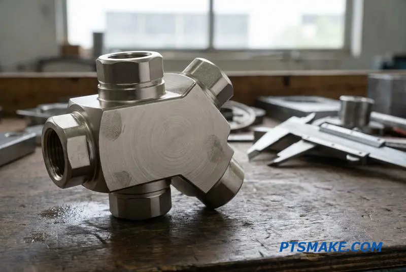
The choice of a valve body surface treatment is never arbitrary; it’s a strategic decision based on system chemistry and mechanics. For instance, in a mixed-metal loop containing copper and aluminum, proactive coating is essential to prevent issues.
Selecting the Right Treatment
The coolant itself is the biggest factor. A water-glycol mix is conductive and requires protection against corrosion. In contrast, dielectric fluids are non-conductive, so electrical insulation from anodizing becomes more important for preventing arcing.
Matching Treatment to Application
In our work at PTSMAKE, we’ve found that passivating 316L stainless steel per ASTM A967 is standard for most water-based coolants. It removes surface contaminants from machining, which is a common source of premature rust. For copper alloy bodies, Electroless Nickel Plating14 is my go-to recommendation for liquid cooling. It creates a completely uniform barrier, unlike electroplating, which can build up unevenly on complex shapes.
This uniformity is critical inside the intricate passages of CNC Machined Fittings and Valves for Liquid Cooling. For low-friction needs, like on valve stems, a Teflon impregnation or a Xylan coating reduces actuation force and prevents sticking, especially after long idle periods.
| Coolant Type | Common Material | Recommended Treatment | Key Benefit |
|---|---|---|---|
| Water-Glycol | 316L Stainless | Passivation | Corrosion Resistance |
| Water-Glycol | Aluminum | Hard Anodize (Type III) | Hardness, Corrosion Shield |
| Water-Glycol | Copper/Brass | Electroless Nickel | Uniform Barrier Layer |
| Dielectric Fluid | Aluminum | Hard Anodize (Type III) | Electrical Insulation |
Choosing the right surface treatment is crucial for preventing system failure. Passivation, anodizing, and specialized plating directly enhance the durability and reliability of liquid cooling components, ensuring they meet performance expectations over their entire lifespan.
Design for Manufacturability: Valve Body Drawings That Machinists Love
A well-designed valve body drawing is more than a set of instructions; it’s a clear communication tool. When engineers apply Design for Manufacturability (DFM) principles, they bridge the gap between design intent and production reality, saving time and reducing costs. This approach prevents unnecessary revisions and streamlines the machining process.
Why DFM Matters for Valve Bodies
Effective DFM anticipates manufacturing challenges. For complex components like CNC Machined Fittings and Valves for Liquid Cooling, small design adjustments can have a significant impact. They can eliminate the need for specialized tooling or secondary operations, directly improving efficiency and component quality.
From Drawing to Finished Part
Here are common issues we see and their DFM solutions:
| Problematic Feature | Optimized DFM Callout |
|---|---|
| Sharp internal corners | Generous corner radii |
| Deep, narrow bores (L/D > 4:1) | Reduced length-to-diameter ratio |
| Non-standard threads | Region-specific standard threads (NPT/BSP) |
| Ambiguous datums | Clear GD&T framework |
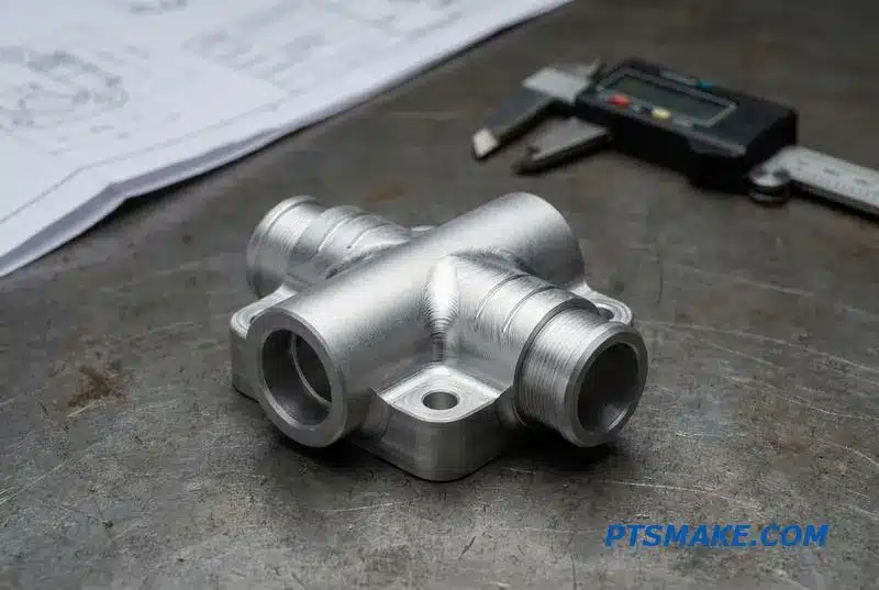
At PTSMAKE, we frequently guide clients on design for manufacturability valve machining. Simple changes yield major benefits. For instance, avoiding deep bores with a length-to-diameter ratio over 4:1 eliminates the need for expensive gundrilling. Deeper bores often lead to increased Tool deflection15, which can compromise hole straightness and overall accuracy.
Key Optimization Areas
Internal Geometries
Specifying generous corner radii in internal pockets is crucial. Sharp corners cannot be milled and require Electrical Discharge Machining (EDM), a much slower and costlier process. Designing ports to be accessible from standard tool orientations also simplifies setups and reduces machining time significantly.
Threads and Tolerances
Using non-standard threads for a specific region, like BSP in a US-based project, can cause sourcing delays. Equally important are clear datum definitions for Geometric Dimensioning and Tolerancing (GD&T), which remove ambiguity and ensure parts meet functional requirements consistently.
| Design Choice | Machining Implication |
|---|---|
| Sharp Internal Corner | Requires slow, costly EDM process |
| L/D Ratio > 4:1 | Needs specialized deep-hole drilling tools |
| Ambiguous GD&T | Risk of misinterpretation and scrap parts |
| Standard Port Access | Enables faster, more rigid setups |
By focusing on DFM principles like optimizing bore depths, using standard threads, and providing clear GD&T, you can create valve body drawings that are efficient to produce. These small adjustments lead to lower costs, faster lead times, and higher quality parts.
Common Machining Defects in Valve Bodies and How to Avoid Them
Valve bodies used in liquid cooling systems must be flawless. Even small errors in these CNC machined fittings and valves can cause leaks or system failure. We often see specific issues that compromise performance, but with the right approach, they are entirely preventable.
Out-of-Round Bores
A primary concern is bores that are not perfectly circular. This often results from an improper clamping strategy, where fixture pressure deforms the part slightly during machining. When released, the part springs back, leaving an out-of-round bore that compromises sealing.
Surface Finish Imperfections
Another common problem is chatter marks on critical sealing faces. These small vibrations, often caused by interrupted cuts or tool instability, create a rough surface. This prevents a perfect seal, leading to leaks over time and creating major CNC valve quality issues.
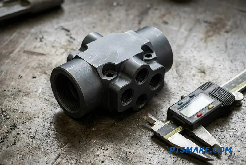
Addressing valve body machining defects requires a systematic process. It’s not just about fixing one issue; it’s about building a process that anticipates and prevents them. We focus on identifying the root cause, implementing precise detection, and refining the machining strategy for long-term reliability.
Common Defects and Solutions
Understanding the source of a defect is the first step. For instance, thread failures often trace back to simple tool wear that wasn’t monitored. Likewise, porosity in a cast part only becomes a problem after we start machining it, revealing hidden voids. Each defect has a specific cause and solution.
| Defect | Root Cause | Detection Method | Corrective Action |
|---|---|---|---|
| Out-of-Round Bores | Insufficient clamping | CMM, Air Gaging | Redesign fixture, use torque wrenches |
| Chatter Marks | Tool vibration, interrupted cuts | Surface profilometer | Adjust speeds/feeds, use rigid tooling |
| Thread Failures | Tool wear | Go/No-Go Gage | Implement tool life management |
| Internal Burrs | Cross-drilling operations | Borescope inspection | Add deburring cycle, use special tools |
| Porosity | Poor casting quality | Visual, Pressure Test | Improve casting process, screen raw parts |
| Dimensional Drift | Thermal growth, tool wear | In-process probing | Implement tool compensation, manage coolant |
We also pay close attention to dimensional drift during long production runs. Changes in machine temperature and gradual tool wear can cause part dimensions to slowly move out of spec. This requires robust process control and expertise in Dimensional Metrology16 to maintain consistency from the first part to the last.
Preventing valve body defects requires a deep understanding of root causes, from clamping forces to thermal drift. Using precise detection methods and proactive process control is essential for ensuring the reliability of CNC machined fittings and valves for liquid cooling systems.
Prototyping to Production: Scaling Valve Body Manufacturing
Scaling a new valve body design from a single prototype to full production requires a phased approach. Each stage addresses different goals, from validating the design to optimizing for cost and repeatability at high volumes. This journey is crucial for project success.
The Prototyping Phase (1-10 Pieces)
The initial stage focuses on speed and design validation. We typically use 5-axis or mill-turn centers to machine parts from solid bar stock. This allows for rapid iteration, with turnarounds of 2-3 weeks, enabling quick adjustments based on testing feedback.
Pilot to Production (10-10,000+ Pieces)
As volume increases, the strategy shifts. The pilot run introduces production-grade fixturing and optimized toolpaths. Full production demands dedicated workholding, minimized cycle times, and robust quality control systems to ensure consistency across thousands of parts.
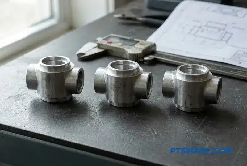
Moving beyond the initial prototypes introduces critical decisions about manufacturing methods. The right choice directly impacts unit cost, lead time, and part quality. Understanding these trade-offs is key to scaling effectively for products like CNC Machined Fittings and Valves for Liquid Cooling.
Choosing the Right Path
A primary consideration is the transition from machining from solid material to investment casting. For lower volumes, machining from bar stock is faster and avoids high tooling costs. As quantities exceed a few thousand units, the upfront cost of casting tooling is offset by lower material waste and reduced machining time.
| Volume Range | Primary Method | Key Advantage |
|---|---|---|
| 1-100 pcs | Fully Machined from Solid | Speed, No Tooling Cost |
| 100-2,000 pcs | Optimized Machining | Reduced Cycle Time |
| 2,000-10,000+ pcs | Investment Casting + Machining | Lower Unit Cost |
For extremely high volumes, we evaluate multi-spindle automation to further drive down cycle times. Quality assurance also matures from first-article inspection in the pilot phase to using Statistical Process Control17 during full production, which helps us monitor and control the manufacturing process in real-time.
Successfully scaling valve body manufacturing hinges on a strategic transition from flexible prototyping to optimized mass production. Choosing the right processes, like casting or automation, and implementing robust quality controls are critical for achieving cost-effectiveness and consistency at high volumes.
Regulatory and Industry Standards for Data Center Cooling Valves
In data center liquid cooling, standards are not just recommendations; they are the foundation for reliability and interoperability. Adhering to them ensures that every component, especially CNC Machined Fittings and Valves for Liquid Cooling, performs as expected under demanding conditions. This framework prevents costly failures and ensures system compatibility.
Key Governing Bodies
Several organizations publish standards critical to valve manufacturing. Groups like ASME, ANSI, and the Open Compute Project (OCP) provide the specific guidelines we follow. These rules dictate everything from material strength to the precise dimensions of a connection port, directly influencing the machining process.
Why Standards Matter
Following these standards guarantees that a valve can handle the system’s pressure and temperature, connects seamlessly with other components, and operates safely. For manufacturers like us at PTSMAKE, this means translating complex specifications into precise physical parts that our clients can trust completely.
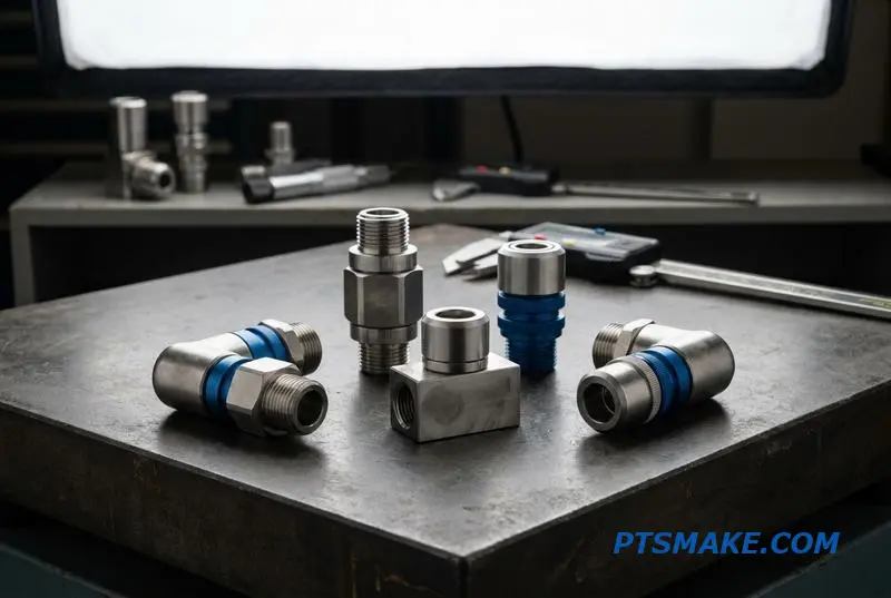
Understanding the landscape of data center valve standards requires distinguishing between mandatory regulations and industry best practices. This distinction guides our manufacturing approach, ensuring both compliance and performance for mission-critical components.
Mandatory vs. Recommended Standards
Safety certifications like UL 1995 are often mandatory for electronic equipment, including cooling systems. In contrast, standards from ASHRAE TC 9.9 or OCP are typically considered industry-driven best practices. However, major data center operators often require OCP compliance for interoperability, making it a de-facto requirement for suppliers.
Impact on Machining Requirements
These standards have a direct and significant impact on manufacturing processes. For instance, ANSI/FCI 70-2 defines valve seat leakage classes. Achieving a Class VI shutoff requires extremely tight tolerances on machined surfaces, something we focus on intently. OCP standards for rack interfaces specify exact dimensions for UQD/BMQC couplings. Every port location, thread size, and surface must adhere to a specific Datum18 to ensure a perfect fit across different vendors’ equipment.
The following table summarizes key standards:
| Standard | Focus Area | Machining Implication |
|---|---|---|
| ASME B16.34 | Valve Pressure-Temperature Ratings | Specifies material strength and wall thickness requirements. |
| ANSI/FCI 70-2 | Control Valve Seat Leakage | Dictates surface finish and tolerance for sealing surfaces. |
| OCP V3 UQS | Rack & Manifold Interfaces | Defines precise dimensions, port locations, and thread sizes. |
| UL 1995 | Cooling Equipment Safety | Governs material selection and electrical safety design. |
Finally, a robust quality system like ISO 9001 is essential. It provides the framework to ensure we can consistently produce parts that meet all these demanding specifications.
Adhering to standards like ASME, ANSI, and OCP is crucial for the safety and reliability of data center cooling systems. These regulations directly influence precision machining requirements, ensuring every valve and fitting performs flawlessly and integrates seamlessly within the infrastructure.

Discover how this surface quality optimizes fluid flow and enhances the efficiency of high-performance cooling systems. ↩
Understanding this phenomenon helps prevent valve damage and ensures long-term system stability in high-flow applications. ↩
Understand how this electrochemical process degrades components and learn effective prevention strategies for mixed-metal systems. ↩
Understand how this geometric tolerance is critical for high-pressure sealing performance. ↩
Understand how this static friction phenomenon impacts precision fluid control systems and component longevity. ↩
Explore how this geometric tolerance ensures perfect alignment and prevents leaks in high-performance fluid systems. ↩
Understanding hysteresis helps optimize valve reseating performance and system efficiency. ↩
Learn how this control technology enables ultra-precise tool movement in complex 5-axis machining. ↩
Learn how this process improves material properties for high-performance valve components. ↩
Understanding this core CNC motion helps in specifying advanced machining operations for superior thread quality. ↩
Explore how tribology helps create durable, leak-free metal-to-metal seals by managing microscopic friction and wear. ↩
Understand how this method provides the highest sensitivity for detecting microscopic leaks in critical sealed systems. ↩
Learn how this tool enables non-destructive visual inspection of critical, hard-to-reach internal features. ↩
Understand how this uniform coating process protects complex internal geometries in precision fluid control components. ↩
Understanding tool deflection helps predict and prevent dimensional inaccuracies, especially for deep or thin-walled features. ↩
Explore how the science of measurement ensures part conformity and quality in manufacturing. ↩
Understand how this data-driven method ensures consistent quality in high-volume manufacturing. ↩
Understanding the role of a datum is key to achieving the precise geometric tolerances required in high-performance components. ↩