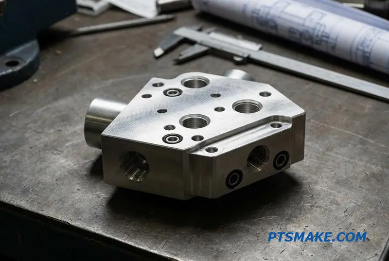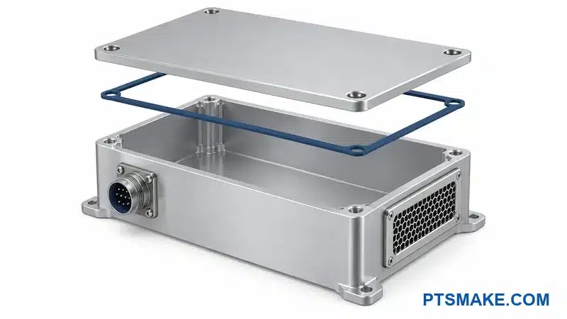

Are your AI racks still hitting thermal bottlenecks even after upgrading to liquid cooling? The problem might not be your cold plates or CDU. It could be the manifold quietly creating hotspots, pressure imbalance, and pump strain across your entire deployment.
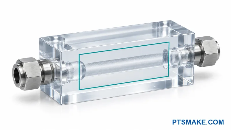
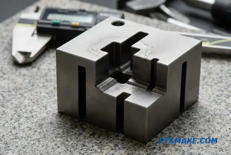
Custom CNC machined manifolds give data center liquid cooling systems balanced flow, leak-free port interfaces, and precise dimensions that off-the-shelf parts can’t deliver. They are the distribution hub that decides whether every server in a high-density rack gets the coolant it needs.
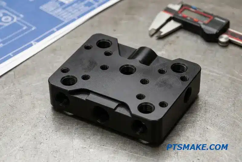
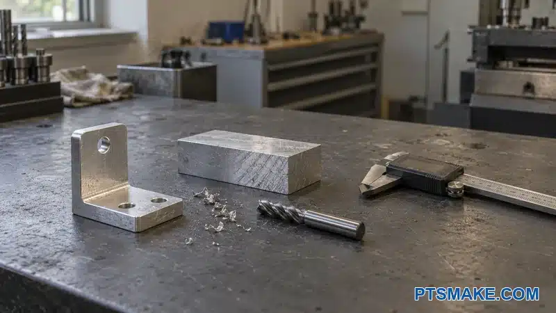
I’ve spent years helping engineering teams move from generic manifolds to custom CNC solutions, and the performance gap is real. In this guide, I’ll walk you through the design, material, and machining details that separate a reliable manifold from one that creates problems down the line.
Your Liquid Cooling System Is Only as Strong as Its Fluid Distribution
In data center cooling, cold plates and Coolant Distribution Units (CDUs) often steal the show. However, the system’s true performance hinges on a less celebrated component: the liquid cooling manifold. This is the central hub that ensures balanced coolant flow to every server.
The Critical Distribution Hub
Think of the manifold as the heart of your rack’s fluid network. A poorly designed one creates uneven flow, leading to hotspots, pressure imbalances, and reduced pump efficiency. The entire cooling strategy can succeed or fail based on this single part’s ability to distribute fluid evenly.
Consequences of Poor Manifold Design
Even the most powerful CDU is useless if the coolant doesn’t reach its destination effectively. The table below highlights the risks associated with subpar rack manifold flow distribution.
| Issue | Impact on System |
|---|---|
| Flow Imbalance | Hotspots and server throttling |
| High Pressure Drop | Increased pump power consumption |
| Leaks | Catastrophic equipment failure |
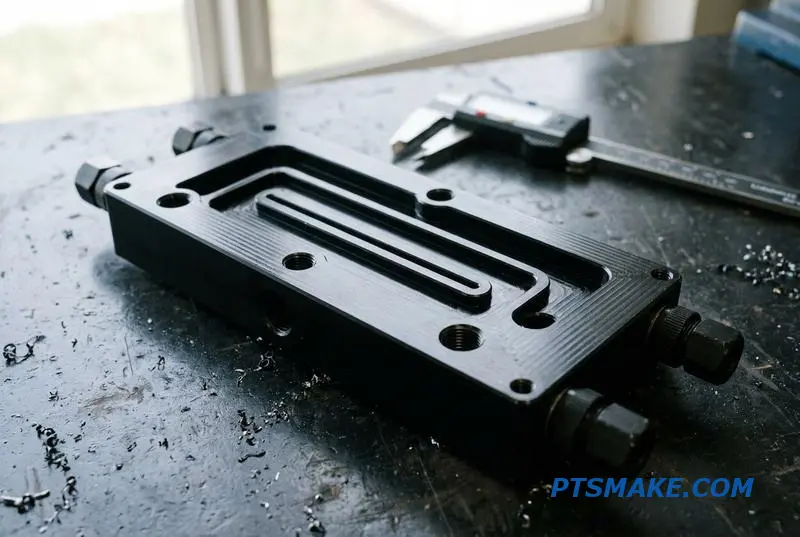
Effective manifold design goes beyond simple plumbing. It requires a deep understanding of how internal geometry impacts system-wide performance. At PTSMAKE, we focus on precision machining to create optimized flow paths that minimize pressure drop and ensure uniform distribution.
Material Selection and Performance
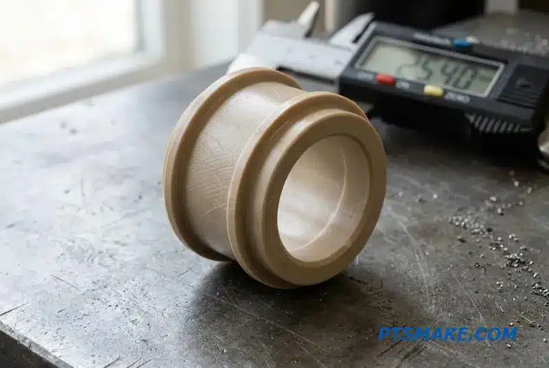
The choice of material for liquid cooling manifolds is critical. It affects not only thermal conductivity and durability but also manufacturing complexity and cost. Aluminum is common for its balance, but copper or even specialized polymers might be better for specific applications.
| Material | Key Advantage | Common Application |
|---|---|---|
| Aluminum (6061) | Cost-effective, good thermal properties | General data centers |
| Copper | Superior thermal conductivity | High-density computing |
| PPS/PEEK | Corrosion resistance, lightweight | Harsh environments |
The Role of Precision in Flow Dynamics
The internal channels of a manifold must be perfect. Any burrs or surface imperfections from machining can disrupt the flow. This is where the principles of Fluid Dynamics1 become crucial. Achieving laminar flow and avoiding turbulence requires extremely tight tolerances, which is a core focus of our manufacturing process.
A well-engineered liquid cooling manifold is the backbone of a reliable DLC system. Its design, material, and manufacturing precision are not minor details; they are fundamental to achieving balanced flow, preventing hotspots, and ensuring overall operational efficiency for the entire rack.
In-Rack vs. Row-Based Manifolds — Which Architecture Fits Your Deployment
Choosing the right liquid cooling manifold architecture is a critical decision. The two primary configurations, in-rack and row-based, serve distinct needs. Your choice impacts efficiency, scalability, and maintenance for the entire system’s lifecycle. Let’s break down the fundamentals of each approach.
In-Rack Manifold Systems
In-rack manifolds are mounted directly within or onto a server rack, either vertically or horizontally. This design provides targeted liquid cooling for high-density components inside a single enclosure. It’s an ideal solution for deployments where specific racks have extreme heat loads.
Row-Based Manifold Systems
Row-based systems serve multiple racks from a centralized distribution point. These assemblies run either above or below the floor, creating a more organized infrastructure for large-scale data centers. This architecture is built for uniformity and scalability across entire rows.
| Manifold Type | Best Use Case |
|---|---|
| In-Rack | High-density individual racks |
| Row-Based | Large-scale, uniform deployments |
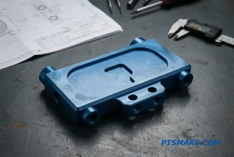
When we move beyond the basic definitions, the practical trade-offs become clear. The decision between an in-rack or row-based manifold for your data center involves balancing accessibility, space, and future growth.
Maintenance and Accessibility
In-rack manifold liquid cooling is straightforward to service on a per-rack basis. Technicians can isolate a single rack without disrupting others. However, in a large deployment, managing hundreds of individual manifolds can become complex and time-consuming.
Row-based systems centralize the main connections, which can simplify large-scale maintenance and monitoring. The challenge here is that any work on the main manifold might affect an entire row of racks, requiring more coordinated downtime.
Scalability and Space Usage
A vertical manifold vs horizontal manifold DLC debate often centers on space within the rack. Both configurations consume valuable rack U-space. While effective, this can be a limitation. Row-based systems, in contrast, preserve this space by using overhead or sub-floor pathways.
For this reason, row-based architecture is inherently more scalable for hyperscale deployments. It allows for a predictable, modular expansion. At PTSMAKE, we find that most liquid cooling manifolds are configured-to-order, as off-the-shelf solutions rarely fit perfectly. Precision CNC machining allows us to create manifolds that meet exact flow, pressure, and port requirements, avoiding issues like Cavitation2.
| Feature | In-Rack Manifold | Row-Based Manifold |
|---|---|---|
| Space Usage | Consumes valuable rack U-space | Utilizes overhead or under-floor space |
| Scalability | Per-rack, granular expansion | High, for entire rows or pods |
| Maintenance | Isolated, simpler for single rack | Centralized, can impact entire row |
Ultimately, the choice hinges on your deployment’s scale and density. In-rack manifolds offer precise, localized cooling for high-performance racks, while row-based systems provide a scalable, organized framework for large data centers. Both require careful planning to ensure optimal performance.
Why Off-the-Shelf Manifolds Fall Short for High-Density AI Racks
Standard liquid cooling manifolds are simply not built for the demands of modern AI infrastructure. Systems like the NVIDIA NVL72 generate immense heat, requiring cooling solutions that are far from standard. Off-the-shelf parts create performance bottlenecks and reliability risks.
The Customization Gap
Off-the-shelf components follow a one-size-fits-all approach. However, high-density AI racks demand precise specifications for optimal performance. Any deviation can compromise the entire cooling loop.
Standard vs. Custom Manifolds
| Feature | Off-the-Shelf Manifold | Custom CNC Manifold |
|---|---|---|
| Port Spacing | Fixed, generic layout | Matched to specific server blades |
| Flow Rate | Standard, often insufficient | Optimized for high-power GPUs |
| Material | General-purpose aluminum/plastic | Selected for coolant compatibility |
| Form Factor | Fits standard rack depths | Designed for any custom rack size |
This gap highlights why a custom approach is essential for mission-critical AI hardware.
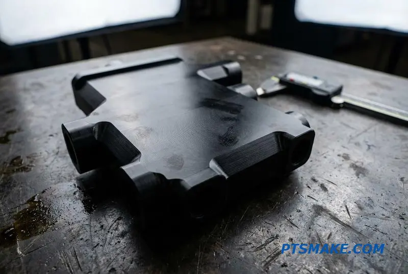
The limitations of off-the-shelf manifolds become clear during integration. I’ve seen projects delayed because a standard part had the wrong port thread type, creating leaks under pressure. Others failed because the port count was insufficient for the number of GPUs in a single chassis.
Addressing High-Density Rack Requirements
AI data centers often use non-standard rack depths to accommodate complex cabling and hardware. An off-the-shelf manifold with the incorrect form factor can obstruct airflow or prevent the rack door from closing. This is a common but easily avoidable issue with a custom design.
Critical Mismatches and Solutions
High-flow Coolant Distribution Units (CDUs) operate at pressures that standard manifolds cannot handle. This mismatch leads to catastrophic failures. The required Volumetric Flow Rate3 for a 140kW+ cluster is something standard parts are not tested for. CNC machining solves these issues by enabling complete design control.
| Mismatch Issue | Consequence | CNC Machining Solution |
|---|---|---|
| Incorrect Port Threads | Leaks, system downtime | Precise thread milling (NPT, BSPP, etc.) |
| Low Pressure Rating | Manifold failure, coolant spills | Thicker walls, material reinforcement |
| Wrong Form Factor | Installation impossible | Custom dimensions to fit any space |
At PTSMAKE, we machine liquid cooling manifolds to exact specifications, ensuring every parameter meets the demands of the application.
Off-the-shelf manifolds are a liability in high-density AI systems. Their generic design fails to meet the specific flow, pressure, and dimensional requirements. Custom CNC machined liquid cooling manifolds provide the only reliable solution, ensuring performance and preventing costly failures.
Stainless Steel, Aluminum, or Copper — Manifold Material Selection Based on Coolant and Environment
Choosing the right material for liquid cooling manifolds is a critical decision that directly impacts system reliability. The selection goes beyond thermal performance, extending into chemical compatibility with coolants and the operational environment. Each material presents a unique balance of cost, weight, and durability.
Primary Material Options
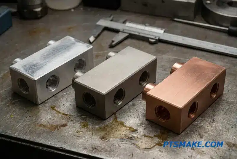
Stainless steel, aluminum, and copper are the most common choices. While copper offers superior thermal conductivity, this feature is often not the primary requirement for a manifold, which mainly serves as a distribution hub for the coolant.
High-Level Comparison
The best choice depends on your specific system requirements, including the type of coolant used and other metals present in the cooling loop.
| Material | Key Advantage | Main Consideration |
|---|---|---|
| Stainless Steel | Corrosion Resistance | Higher Cost/Weight |
| Aluminum | Lightweight & Lower Cost | Corrosion Susceptibility |
| Copper | Thermal Conductivity | High Cost & Weight |
In-Depth Material Analysis
At PTSMAKE, we frequently guide clients through this decision for applications ranging from data centers to industrial machinery. The optimal choice is rarely based on a single property but on a holistic view of the system’s design and long-term goals.
Stainless Steel (304/316)
For most high-reliability systems, 304 or 316 stainless steel is the industry standard. It is highly resistant to corrosion and compatible with nearly all common coolants, including deionized water and glycol mixtures. This makes a stainless steel liquid cooling manifold a safe, long-lasting choice for critical applications.
Aluminum
Aluminum is an excellent option when weight and cost are primary drivers. However, its use requires careful system design due to its susceptibility to galvanic corrosion4, especially when paired with copper components like cold plates. For proper aluminum manifold coolant compatibility, glycol-water mixtures must contain specific corrosion inhibitors.
Copper
While copper is the best conductor of heat, it is rarely the best choice for a manifold. Its primary function is fluid distribution, not heat dissipation. The high cost and weight of copper often make it an unnecessary expense for this component of the cooling loop.
Coolant and Seal Interactions
Your coolant choice dictates seal material. Standard coolants work well with an EPDM seal manifold, but aggressive dielectric fluids demand a more robust material like FKM (Viton) to prevent leaks and degradation over time.
| Coolant Type | Recommended Seal | Key Consideration |
|---|---|---|
| Water/Glycol | EPDM | Ensure inhibitors are used with aluminum. |
| Dielectric Fluid | FKM (Viton) | Verify fluid compatibility with the specific FKM grade. |
Your material choice for liquid cooling manifolds must balance cost, performance, and chemical compatibility. Stainless steel offers the highest reliability, while aluminum is a lighter, cost-effective option that demands careful coolant management to prevent corrosion and ensure system longevity.
How CNC Machining Enables Manifold Designs That Welded Assemblies Cannot Match
When designing fluid systems, especially for applications like Liquid Cooling Manifolds, the choice between a welded assembly and a CNC machined block is critical. Welded manifolds might seem straightforward, but they introduce significant performance risks. The internal weld bead disrupts flow and creates areas where contaminants can accumulate.
The Hidden Flaws of Welded Manifolds
Welded pipe manifolds suffer from inherent drawbacks that can compromise system integrity. The interior weld bead is a major issue, creating turbulence and potential pressure drops. This irregularity also makes complete system flushing difficult, trapping particles that can damage sensitive downstream components over time.
Why CNC Machining Excels
In contrast, CNC-machined block manifolds offer a superior alternative. By carving fluid channels from a solid block of material, we achieve perfectly smooth internal bores. This eliminates flow discontinuities and contamination risks, ensuring optimal performance and system cleanliness from the start.
Feature Comparison: CNC vs. Welded
| Feature | CNC Machined Manifold | Welded Pipe Manifold |
|---|---|---|
| Internal Finish | Smooth, continuous bore | Rough internal weld bead |
| Flow Path | Optimized, laminar flow | Turbulent, disrupted flow |
| Contamination Risk | Minimal | High (particle traps) |
| Leak Points | Minimized (single block) | Multiple (at each weld) |
A one-piece CNC manifold provides unmatched design freedom. We can integrate complex, multi-directional channels and numerous ports into a single, compact block. This approach drastically reduces the number of potential leak points compared to an assembly with multiple welded joints, enhancing overall system reliability.
Achieving Unmatched Precision
The precision of CNC machining is a key advantage. At PTSMAKE, we consistently hold port-to-port spacing within ±0.05mm. This level of accuracy is nearly impossible to achieve with manual welding and fitting, ensuring perfect alignment and consistent performance across all connections in the system.
The Impact on Fluid Dynamics
Smooth, precisely machined channels promote predictable fluid behavior. Understanding Bernoulli’s principle5 helps illustrate how inconsistencies from welding can cause unwanted pressure and velocity variations. A CNC-machined manifold ensures stable flow, which is critical for efficient data center fluid distribution and other sensitive applications.
A Hybrid Solution
For certain designs, a hybrid approach offers a practical compromise. We can CNC machine a central port block that houses the most critical connections and then weld tube extensions onto it. This combines the precision of a machined block with the flexibility of welded tubing for simpler sections.
CNC machining delivers superior manifold designs by creating smooth internal paths, enabling complex geometries in a single block, and ensuring high precision. This method overcomes the flow disruption, contamination risks, and inconsistencies inherent in welded assemblies, boosting system performance and reliability.
Cross-Drilled Ports and Internal Flow Paths — The Machining Challenge Hidden Inside Every Manifold
The performance of Liquid Cooling Manifolds depends on their internal geometry. Cross-drilled ports and complex flow paths are essential, but they introduce significant machining challenges. These features are often hidden from view yet are critical for system reliability and efficiency.
The Problem of Deep Holes
Drilling a deep hole is not straightforward. When the length-to-diameter (L/D) ratio exceeds 20:1, standard drills struggle. Chip evacuation becomes a major issue, leading to tool breakage and poor surface finish inside the manifold.
Intersecting Bores and Burrs
Every intersection between a main bore and a cross-drilled port creates a burr. If not removed, these tiny metal fragments can break free. They then contaminate the coolant loop, risking damage to sensitive components downstream.
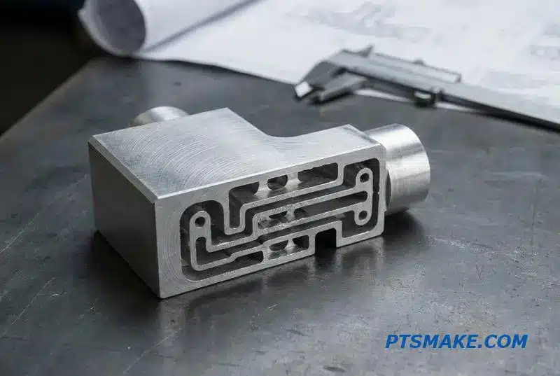
Achieving a flawless internal pathway in a manifold requires specialized techniques. Standard twist drills are often inadequate for deep holes. We must choose the right tools and processes to ensure precision and cleanliness inside every cross drilled manifold port.
Gun Drilling vs. Twist Drilling
Gun drilling is a preferred method for creating deep, straight holes. Unlike standard drills, it uses high-pressure, through-spindle coolant to flush chips out continuously. This prevents chip packing and results in a superior internal bore finish. This finish is crucial, as a rough surface increases pressure drop.
| Feature | Gun Drilling | Standard Twist Drilling |
|---|---|---|
| L/D Ratio | Exceeds 300:1 | Typically < 10:1 |
| Coolant Delivery | Through the tool | External flood |
| Chip Evacuation | Excellent (flushed out) | Poor (requires pecking) |
| Hole Straightness | High | Moderate |
| Surface Finish | Superior | Standard |
The Critical Deburring Step
After drilling, internal deburring is non-negotiable. It’s a meticulous process to create a chip-free coolant path. We often use thermal or electrochemical methods for inaccessible intersections. For any peck drilling6 operation, chip management is the key to preventing internal flaws that could compromise the entire cooling system. Modern CNC machining centers with through-spindle coolant are ideal for these tasks.
The internal quality of a manifold is just as important as its external appearance. Managing deep hole drilling, chip evacuation, and burr removal is essential for creating reliable, high-performance Liquid Cooling Manifolds that meet strict operational requirements.
Port Spacing, Thread Type, and Orientation — Getting the Interface Right for Every Server Slot
Getting the interface right is non-negotiable. A liquid cooling manifold’s success depends entirely on how well its ports align with server slots. Misalignment means connection failure, leaks, and costly downtime. Every detail matters for a perfect fit.
Matching Rack Unit Spacing
The first step is matching the manifold port spacing to the rack’s U-height. Whether it’s 1U, 2U, or 4U, the port locations must be exact. This requires precision manufacturing to ensure every connection point lines up perfectly with the server’s input and output.
| Rack Unit | Standard Height | Typical Port Configuration |
|---|---|---|
| 1U | 1.75 inches | Single row, compact spacing |
| 2U | 3.5 inches | Single or double row |
| 4U | 7.0 inches | Multiple rows, high density |
Connection and Orientation
Finally, consider the manifold port orientation. Front or rear connections dictate the entire layout. For blind-mate systems, left or right-handed orientations are critical for quick-disconnects (QDs) to engage without visual confirmation. Hand-mated connections allow more flexibility but still require thoughtful placement.
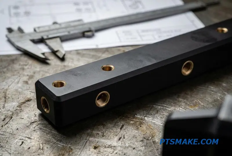
The thread type is another critical decision, often dictated by regional standards or specific application needs. Choosing the wrong one guarantees leaks. It’s a common point of failure I see when designs are not carefully reviewed before manufacturing begins.
Common Thread Types
NPT is common in the US, using a tapered design to create a seal. BSPP (or G-thread) is standard in Europe, requiring a gasket for a seal. SAE O-ring boss threads are excellent for high-vibration environments as the O-ring provides a superior seal.
| Thread Type | Sealing Method | Common Region | Key Advantage |
|---|---|---|---|
| NPT | Thread Taper | North America | Widely available |
| BSPP (G) | Gasket/Washer | Europe/Asia | Reusable, no sealant needed |
| SAE ORB | O-Ring | Global | Excellent vibration resistance |
The CNC Machining Advantage
This is where precision CNC machining becomes essential for liquid cooling manifolds. We can accurately place ports to match any manifold port spacing rack configuration. Our machines can cut multiple thread types, like NPT and BSPP, on the same manifold to interface with diverse hardware.
Furthermore, CNC allows for custom manifold port orientation. We can machine outlets at 45 or 90 degrees to navigate tight spaces. This flexibility is impossible with off-the-shelf components. The reliability of a threaded port manifold in a data center relies on this precision, especially for tapered threads7, which require exact geometry.
Perfectly integrating liquid cooling manifolds requires precise control over port spacing, thread type, and orientation. CNC machining provides the necessary accuracy and flexibility to meet any server rack specification, ensuring a reliable, leak-free connection for every single server slot.
O-Ring Groove Design for Manifold-to-QD Connections — Why Retrofitting Leaks Starts Here
The connection between a manifold and a quick-disconnect (QD) fitting is a frequent source of leaks in fluid systems. The problem almost always traces back to the O-ring groove design. Proper sealing is a game of precision, not just material selection.
Key Design Elements
An effective seal depends on three core factors: the groove’s shape, the O-ring’s compression, and the surface finish. Getting any of these wrong introduces a potential failure point, especially in liquid cooling manifolds where temperature changes cause materials to expand and contract.
Groove Type Selection
The choice between a standard rectangular groove and a dovetail groove impacts O-ring retention during assembly and maintenance. While dovetail grooves hold the O-ring captive, they are more complex to machine.
| Groove Type | Primary Use Case | Key Advantage |
|---|---|---|
| Rectangular | Standard static face seals | Simple to machine |
| Dovetail | Captive O-ring applications | Prevents O-ring fallout |
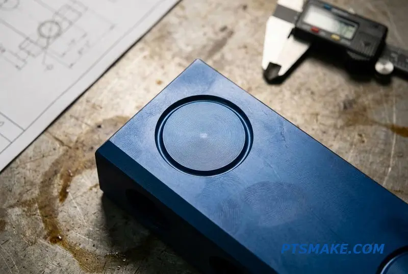
Achieving the Ideal Compression Ratio
For most standard O-rings in static applications, a compression ratio of 15-25% is ideal. Too little compression, and the seal won’t engage properly under low pressure. Too much, and you risk damaging the O-ring or creating excessive assembly force, leading to premature failure.
The Critical Role of Surface Finish
A smooth surface is essential for a reliable seal. We specify a surface finish of Ra 0.8μm or better on both the groove bottom and sidewalls. A rougher surface can create microscopic leak paths across the sealing face. The science of measuring surface texture, known as Surface metrology8, is fundamental to diagnosing and preventing these failures.
Why CNC Machining is the Solution
This is where manufacturing methods make a significant difference. Molded parts often have inconsistencies from shrinkage and draft angles, making it difficult to maintain tight tolerances. This explains why one manifold may seal perfectly while another identical one leaks. CNC machining produces perfectly consistent groove dimensions every time.
| Feature | CNC Machining | Injection Molding |
|---|---|---|
| Groove Tolerance | High (e.g., ±0.05mm) | Lower (e.g., ±0.15mm+) |
| Surface Finish | Excellent (Ra < 0.8μm) | Variable, often requires post-processing |
| Part Consistency | Virtually identical | Subject to process variations |
At PTSMAKE, we machine these features to precise specifications, ensuring every quick disconnect seal interface performs reliably. This eliminates the guesswork and prevents costly leaks in liquid cooling manifolds and other critical systems.
Proper O-ring groove design—addressing type, compression, and surface finish—is essential for reliable connections. Precision CNC machining provides the consistency that molded parts cannot, directly preventing leaks at the quick disconnect seal interface and ensuring long-term system integrity and preventing manifold leak prevention issues.
Pressure Drop Across the Manifold — How Port Design and Internal Bore Diameter Affect System Efficiency
Understanding hydraulic performance is key to system efficiency. The manifold’s internal bore diameter and port sizing are not just design details; they directly impact pressure drop (ΔP). A restrictive design forces the Coolant Distribution Unit (CDU) pump to work harder, which drives up operational expenses over time.
Bore Diameter and Pressure Drop
A larger internal bore generally results in lower fluid velocity and, consequently, a smaller pressure drop. However, an oversized bore can increase material cost and manifold size. Finding the right balance is crucial for optimal performance.
Port Sizing Matters
Port sizing should align with the quick-disconnect (QD) fittings to prevent unnecessary restrictions. Multiple parallel ports are an effective strategy for reducing the overall system pressure drop.
| Bore Diameter (mm) | Typical Flow Rate (L/min) | Estimated Pressure Drop (kPa/m) |
|---|---|---|
| 12.7 (1/2") | 10 – 20 | 15 – 50 |
| 19.0 (3/4") | 20 – 40 | 5 – 20 |
| 25.4 (1") | 40 – 80 | 2 – 8 |
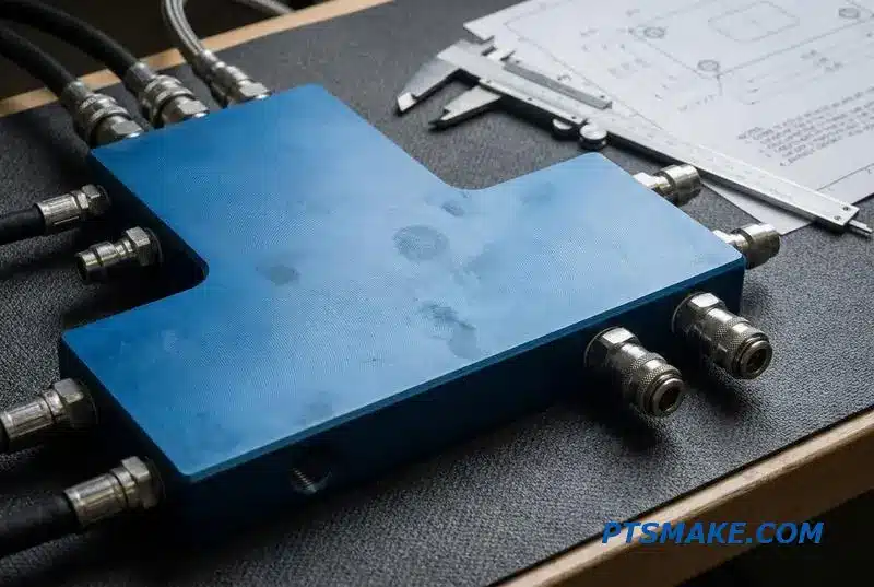
A well-designed liquid cooling manifold maintains optimal flow velocity, typically between 2-4 m/s. Exceeding this range significantly increases pressure drop and pumping power requirements. This directly influences CDU pump sizing and overall manifold resistance, making accurate manifold pressure drop calculation essential.
Parallel Flow and Its Challenges
Using multiple parallel flow paths is a common method to boost parallel flow manifold efficiency. It effectively lowers the overall resistance. However, this design isn’t without risks. On longer manifolds, ensuring balanced flow across all ports can be difficult.
The Risk of Flow Imbalance
Flow imbalance can lead to some components receiving inadequate cooling. This is often caused by the Venturi effect9 where fluid speeds up through constricted areas, causing localized pressure drops. Proper internal geometry and port placement, which we focus on at PTSMAKE, are critical to mitigate this risk.
Proper manifold design, focusing on bore diameter and port sizing, is crucial for managing pressure drop. This optimization directly reduces CDU pump strain and long-term operational costs, ensuring efficient and reliable system performance.
Hot-Swap Capability — How Manifold-Integrated QD Couplings Enable Live Server Maintenance
In data centers, downtime is not an option. Operators need to replace or service servers without shutting down the entire system. This is where a hot swap manifold for a data center becomes essential. It allows for live maintenance, a critical feature for modern infrastructure.
The Key Enabler: Integrated Couplings
Manifolds with integrated quick disconnect (QD) couplings are the solution. They allow technicians to disconnect and reconnect servers from the liquid cooling loop instantly. This design is fundamental to maintaining continuous operation and maximizing uptime, which is the primary goal for any data center manager.
| Feature | Impact on Maintenance |
|---|---|
| Integrated QDs | Enables instant, live server swaps |
| Dry-Break Valves | Prevents coolant spills and air ingress |
| Tool-Free Design | Speeds up the maintenance process |
Eliminating Connection Errors
Furthermore, these systems prevent connection errors. Mismatching supply and return lines can have catastrophic consequences. Color coding and physical keying on the manifold ports make such mistakes virtually impossible. It simplifies a complex task under pressure.
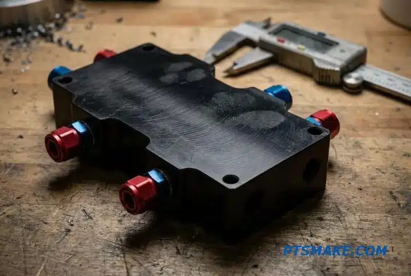
At PTSMAKE, we focus on the practical details that make these systems reliable. A key feature of our liquid cooling manifolds is the tool free quick disconnect manifold design. Technicians can make connections with a simple push, receiving tactile feedback that confirms a secure lock. This eliminates guesswork.
The Importance of Spill-Proof Connections
The integrated dry-break valves are critical for a spill free manifold connection. When disconnected, both the server side and the manifold side seal instantly. This prevents coolant leakage onto sensitive electronics and stops air from entering the cooling loop, which could degrade performance.
Customization for Error-Proofing
To ensure foolproof connections, we implement several features. Color coded manifold ports for data centers are a simple visual guide. More importantly, we use CNC machining to create custom mechanical keying features. This is a real-world application of Poka-yoke10 principles, making it physically impossible to connect a hose to the wrong port.
We can also machine custom mounting brackets and engrave labels directly onto the manifold body. This level of integration, achieved through precision manufacturing, streamlines installation and maintenance, significantly reducing the risk of human error during high-pressure situations.
Manifold-integrated QD couplings are crucial for data center uptime. They enable safe, live server swaps through tool-free, spill-proof connections. Custom features like color-coding and mechanical keying, made possible by CNC machining, prevent costly connection errors and enhance system reliability.
Pressure Relief and Air Bleed Valves — Built-in Safety Features Your Manifold Should Have
In designing liquid cooling manifolds, safety features like pressure relief and air bleed valves are often treated as afterthoughts. However, integrating them directly into the manifold design is crucial for system longevity and performance. These components are not optional add-ons; they are fundamental to a reliable system.
The Role of Pressure Relief Valves (PRV)
A manifold pressure relief valve acts as a critical safeguard. It protects the entire coolant loop from overpressure events, which can be caused by thermal expansion of the fluid or sudden pump surges. Without one, you risk catastrophic failure of tubes, fittings, or the components being cooled.
Why Air Bleed Valves Are Essential
Air bleed valves serve a different but equally important purpose. They allow trapped air to be purged from the system, especially during initial filling. Removing air pockets is essential to prevent flow issues and protect the pump from damage. This is a common requirement for systems like an air bleed manifold in a data center.
| Valve Type | Primary Function | Protects Against |
|---|---|---|
| Pressure Relief Valve (PRV) | Vents excess pressure | Over-pressurization, component damage |
| Air Bleed Valve | Removes trapped air | Pump cavitation, flow starvation |
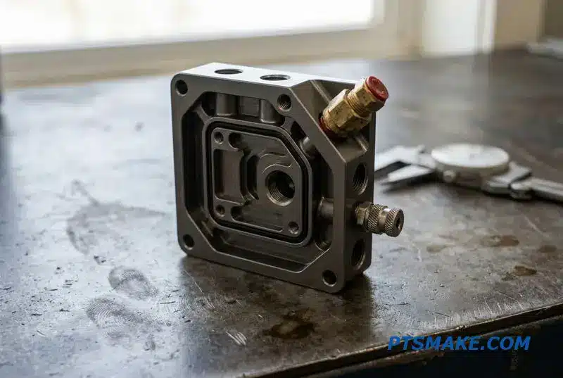
The traditional method of adding these valves involves extra T-fittings and piping. This approach introduces multiple potential points of failure. Every additional connection is a new opportunity for a leak to develop over time due to vibration, thermal cycling, or improper installation. This complicates the assembly and maintenance process.
The Superiority of Integrated Design
Modern CNC machining allows us to integrate ports for these valves directly into the manifold block. This eliminates the need for external fittings, creating a more compact, robust, and leak-resistant system. At PTSMAKE, we machine these features with high precision, ensuring a perfect seal and optimal performance for any coolant loop safety valve.
How Integration Enhances Reliability
An integrated design follows the principle of Pascal’s Law11, where pressure exerted on a fluid is transmitted equally throughout. A single, well-placed PRV can protect the entire system. This streamlined approach not only enhances safety but also simplifies the overall architecture of your liquid cooling manifolds, reducing both assembly time and long-term risk.
| Feature | Traditional Assembly | Integrated Manifold |
|---|---|---|
| Leak Points | Multiple | Minimal |
| Assembly Time | High | Low |
| System Size | Larger Footprint | Compact |
| Reliability | Lower | Higher |
Integrated pressure relief and air bleed valves are essential manifold integrated safety features. Precision CNC machining makes this integration seamless, enhancing system reliability, reducing potential leak points, and simplifying the overall design of liquid cooling manifolds for superior performance and safety.
Mounting and Alignment — Why a Manifold That Doesn’t Fit Right Creates a Domino Effect
A misaligned liquid cooling manifold is more than an inconvenience; it’s the start of a domino effect. Even a millimeter of deviation can cause major system-level problems down the line. This initial error leads to stressed connections and premature wear on critical components.
The Ripple Effects of Misalignment
Poor rack manifold alignment introduces immediate mechanical stress. Quick-disconnect (QD) couplings engage at an angle, leading to accelerated seal degradation and potential leaks. Hose routing becomes compromised, creating kinks that restrict flow and strain fittings, creating another failure point.
Assembly and Maintenance Headaches
The most immediate impact is on assembly and service. Technicians struggle to slide servers into racks, increasing installation time and the risk of damaging sensitive hardware. What should be a simple task becomes a frustrating bottleneck.
| Misalignment Cause | Direct Consequence | Long-Term Impact |
|---|---|---|
| Inaccurate Mounting Holes | Crooked QD Engagement | Accelerated Seal Wear, Leaks |
| Poor Bracket Tolerances | Kinked Hose Routes | Reduced Flow, Fitting Strain |
| Rack Integration Mismatch | Difficult Server Installation | Increased Labor Costs, Damage Risk |
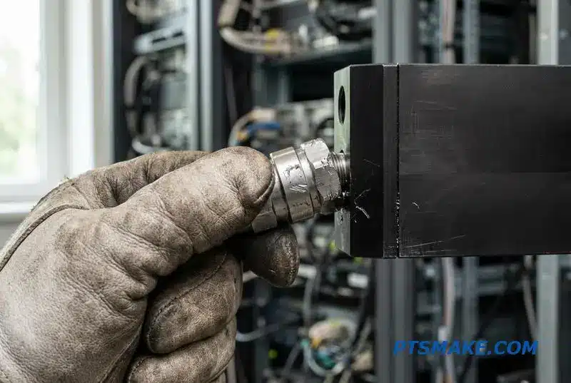
Exploring Mounting Solutions
Traditionally, manifolds are attached using separate brackets or rails. A bracket-mounted solution is common but adds tolerance stack-up issues. A rail-mounted design offers more support but can be complex to integrate into a crowded data center rack environment.
Advanced Integration with Blind-Mate Docking
A more advanced approach is the blind mate manifold docking system. This allows for servers to connect to the cooling loop automatically as they are slid into the rack. However, this demands extreme precision, as even the slightest misalignment will prevent a successful connection.
The CNC Machining Advantage
This is where precision machining becomes essential. At PTSMAKE, we eliminate separate brackets by integrating mounting features directly into the manifold body. We machine precision-drilled and tapped holes, alignment pins, and key slots directly into the part. This single-piece design simplifies assembly and improves reliability.
This level of integration is only possible with tight control over Geometric Dimensioning and Tolerancing (GD&T)12. Successful manifold CAD integration with the rack design is critical. We find that early collaboration between the manifold designer and the rack integrator is the best way to prevent issues.
| Mounting Method | Key Advantage | Primary Challenge |
|---|---|---|
| Bracket-Mounted | Simple Design | Tolerance Stack-Up |
| Rail-Mounted | High Stability | Space and Complexity |
| Integrated (CNC) | Highest Precision | Requires CAD Coordination |
Correct manifold mounting and alignment are foundational to the reliability of the entire liquid cooling system. Integrating mounting features through CNC machining eliminates variables, reduces assembly time, and prevents the cascading failures that stem from a poor initial fit.
Custom Manifold Design from Concept to First Article — The CNC Prototyping Timeline
When planning a custom manifold project, especially for critical applications like liquid cooling systems, understanding the timeline is essential. Setting realistic expectations from the start prevents delays. A well-defined CNC prototyping process ensures a smooth transition from concept to a functional first article.
Key Prototyping Stages
The journey from design to a physical part involves several distinct steps. Each stage has its own timeline, which can vary based on complexity. Clear communication with your manufacturing partner during these phases is key to staying on schedule and achieving the desired outcome for your parts.
Typical Timeline Breakdown
Here is a general timeline for a custom CNC manifold prototype. This assumes standard aluminum or stainless steel bar stock is used.
| Stage | Estimated Time | Notes |
|---|---|---|
| Design Review | 1–2 Days | DFM feedback and final adjustments |
| CAM Programming | 2–3 Days | Complex 5-axis parts take longer |
| Machining | 3–7 Days | Varies with geometry and features |
| Post-Processing | 2–4 Days | Finishing, assembly, and testing |
This process ensures that your custom manifold is ready for testing in a predictable timeframe.
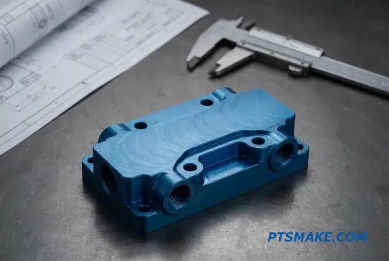
The Advantage of CNC Prototyping
The primary benefit of CNC machining for prototypes is speed. Unlike casting, which requires significant tooling investment and time, CNC machining works directly from a CAD file. This eliminates the long lead times associated with mold making, offering a much faster path to a physical part.
Timeline Comparison: CNC vs. Casting
The difference in lead time is significant. For a custom liquid cooling manifold project, a cast prototype can take months, primarily due to mold creation. A CNC prototype, however, can be produced in a matter of weeks, allowing for rapid iteration and testing.
| Method | Tooling Lead Time | Part Lead Time | Total Estimated Time |
|---|---|---|---|
| CNC Machining | None | 7–21 Days | 1–3 Weeks |
| Casting | 8–12 Weeks | 2–3 Weeks | 10–15 Weeks |
Factors Affecting the Timeline
Several factors influence the overall prototype timeline. The geometric complexity, material availability, and required surface treatments all play a role. During assembly, rigorous leak testing using methods like Helium Leak Detection13 is critical for validating performance, adding a day or two to the process but ensuring reliability. At PTSMAKE, we manage these variables to optimize the manifold design to production cycle.
A custom CNC manifold prototype typically takes 7-21 days, depending on complexity. This agile process avoids the 8-12 week tooling lead time required for casting, enabling faster design validation and getting your product to market sooner.
Leak Testing Rack Manifolds — Why Every Port Must Be Verified Individually
A liquid cooling manifold has multiple ports, and treating them as a single unit during testing is a critical oversight. A leak in just one port compromises the entire system’s integrity. Comprehensive validation requires every potential leak path to be individually verified.
The Problem with Batch Testing
Testing a manifold as a whole can mask subtle, individual port leaks. A small leak at one port might be averaged out across the entire volume, falling below the test’s detection threshold. This creates a false sense of security for a component destined for a critical environment.
A Port-by-Port Mandate
A robust manifold leak test procedure isolates each connection point. This ensures that every seal, thread, and weld meets the required specifications independently. This methodical approach is the only way to guarantee the reliability of the entire assembly.
| Testing Approach | Leak Isolation | Accuracy | Reliability |
|---|---|---|---|
| Batch Testing | Poor | Low | Questionable |
| Individual Port Testing | Excellent | High | Guaranteed |
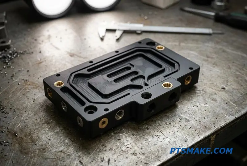
A proper manifold leak test procedure involves several distinct methods, each serving a specific purpose. Ignoring one can leave a critical vulnerability undiscovered. We must move beyond simple pressure checks to ensure total system reliability, especially for high-stakes applications.
Comprehensive Testing Protocols
Structural and Seal Integrity
We start with an individual port pressure decay test, where all other ports are securely plugged. We also perform a hydrostatic test, often taking the manifold to 1.5 times its maximum rated pressure. This verifies the structural integrity of the hydrostatic test cooling manifold under extreme conditions.
Detecting Micro-Leaks
For the most demanding applications, like a helium test manifold for a data center, we use helium mass spectrometry14. This method can detect minuscule leaks down to 10⁻⁶ mbar·L/s, which are completely invisible to pressure decay tests. It’s an essential step for mission-critical components.
| Test Method | Primary Purpose | Common Application |
|---|---|---|
| Pressure Decay | Gross leak detection | General quality control |
| Hydrostatic Test | Structural integrity | High-pressure systems |
| Helium Mass Spec | Micro-leak detection | Data centers, medical |
| Flow Verification | Performance validation | All liquid cooling systems |
At PTSMAKE, we find that our precision CNC machining is key. By producing extremely consistent port geometries and thread profiles, we significantly reduce the initial reject rate during these rigorous tests. Consistent manufacturing translates directly to reliable performance in the field.
Verifying each port individually is non-negotiable for reliable liquid cooling manifolds. This meticulous process, from hydrostatic tests to flow verification, ensures that the component will perform flawlessly under operational stress, preventing costly system failures and ensuring long-term integrity.
Surface Finishing for Manifolds — Passivation, Electroless Nickel, and When Anodizing Is the Wrong Choice
Choosing the right surface finish for a manifold is a critical decision that impacts performance and longevity. It’s not just about appearance. The treatment must match the material and its application, especially for demanding systems like liquid cooling manifolds. Each material has unique needs.
Stainless Steel Requirements
For stainless steel, the goal is maximum corrosion resistance. Machining can leave free iron on the surface, which compromises the steel’s natural protective layer. This is where passivation becomes essential for components used with coolants.
Aluminum and Copper Considerations
Aluminum offers different challenges. While anodizing is common, it may not be suitable for all manifold applications. Copper, though less common, also requires specific treatments to prevent oxidation and maintain system integrity.
| Manifold Material | Primary Finish | Key Benefit |
|---|---|---|
| Stainless Steel (304/316) | Passivation | Removes free iron, restores corrosion resistance |
| Aluminum (6061) | Electroless Nickel | Provides conductivity and corrosion protection |
| Copper | Nickel Plating | Prevents oxide formation |
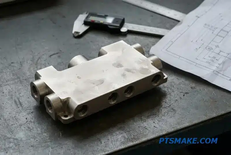
The wrong finish can lead to system failure. I’ve seen aluminum liquid cooling manifolds fail because the designer specified hard anodizing without considering its implications. Anodizing creates a hard, wear-resistant surface, but it is also electrically non-conductive. This can interfere with grounding requirements in complex electronic systems.
A Better Choice for Aluminum
A better option for aluminum manifolds is often electroless nickel plating. This finish provides excellent corrosion protection while maintaining electrical conductivity. It ensures the entire system remains properly grounded, which is a detail that cannot be overlooked.
Material and Coolant Compatibility
The interaction between the manifold material and the coolant is also crucial. For a passivated stainless steel manifold, particularly 316L, a glycol-water mixture works exceptionally well. However, combining pure deionized water with untreated copper can cause rapid corrosion. This is because aggressive ions in the water attack the metal. Improperly treated stainless steel can also suffer from issues like intergranular corrosion15 when exposed to certain environments.
| Finishing Process | Pro | Con | Best For |
|---|---|---|---|
| Passivation | Restores corrosion resistance | Offers no wear resistance | Stainless steel coolant manifolds |
| Electroless Nickel | Conductive, corrosion resistant | Higher cost than anodizing | Aluminum manifolds needing grounding |
| Hard Anodizing | High wear resistance | Electrically non-conductive | Components where insulation is a benefit |
Selecting the right finish is vital for manifold reliability. Passivation is standard for stainless steel, while electroless nickel often outperforms anodizing for aluminum in liquid cooling systems due to conductivity needs. Always consider coolant compatibility to prevent premature failure.
Scaling From Prototype to Rack Farm — How CNC Machining Keeps Manifold Consistency Across Volume
Scaling a validated design from a few prototypes to hundreds of units is a critical step. CNC machining provides the foundation for this growth, ensuring that the 500th liquid cooling manifold is identical to the first. This consistency is built on a repeatable digital workflow.
The Power of Repetition
Once a CAM program is finalized, it becomes the master recipe. Every subsequent part is machined using the exact same toolpaths, fixtures, and quality checks. This process eliminates the variability common in manual or less precise methods, ensuring true manifold scale up manufacturing.
Key Factors in Scaling
| Factor | Prototype (1-10 units) | Production (500+ units) |
|---|---|---|
| Program | Iterative, often adjusted | Locked and validated |
| Tooling | Standard, general-purpose | Optimized, often dedicated |
| Fixturing | Simple, adaptable | Custom, high-throughput |
| Inspection | 100% manual check | First article + sampling |
Scaling requires more than just running the same program repeatedly. It demands strategic planning for high volume manifold production. At PTSMAKE, we often dedicate specific 5-axis machines to a long-running manifold project. This minimizes setup changes and maintains a consistent production environment for optimal results.
Strategic Planning for Production
Material Sourcing
Material costs can also be optimized. Ordering aluminum or copper bar stock in bulk for 500+ units can yield significant savings, often in the range of 10-20%, compared to buying material for small batches. This directly impacts the final cost per part.
Quality Control Protocols
Quality assurance methods must also evolve. While every prototype gets a full inspection, this isn’t practical for large volumes. We implement a first article inspection (FAI) to approve the setup, followed by Statistical Process Control16 to monitor batch consistency. This data-driven approach ensures quality without sacrificing speed.
| Manufacturing Method | Consistency Over Volume | Tooling Wear Impact |
|---|---|---|
| CNC Machining | Extremely High | Minimal, predictable cutter wear |
| Casting | Decreases over time | Mold degradation changes geometry |
This contrasts sharply with methods like casting, where mold wear can subtly alter part dimensions over thousands of cycles. With CNC machining, the digital precision remains absolute, guaranteeing CNC manifold repeatability.
CNC machining ensures that scaling from prototype to full production maintains perfect consistency. Strategic planning for machine capacity, material procurement, and quality control protocols makes the process both reliable and cost-effective for liquid cooling manifolds at volume.

Understanding this principle helps optimize flow paths for better cooling performance and system efficiency. ↩
Understanding this phenomenon helps prevent pump damage and ensures long-term system reliability. ↩
Explore how this metric directly influences thermal management and prevents GPU throttling in high-performance computing environments. ↩
Understanding this electrochemical process is key to preventing premature system failure in mixed-metal cooling loops. ↩
Learn how this principle explains the relationship between fluid speed and pressure in manifold design. ↩
Learn how this drilling technique prevents tool breakage and ensures clean channels in deep-hole operations. ↩
Learn how the geometry of tapered threads creates a metal-to-metal seal and its implications for high-pressure systems. ↩
Understanding this field helps diagnose sealing failures beyond just O-ring material or compression. ↩
This principle helps predict pressure changes, which is essential for designing efficient liquid cooling manifolds. ↩
Discover how this Japanese error-proofing principle from manufacturing is applied to enhance data center system safety and reliability. ↩
Explore this principle to understand fluid pressure distribution in closed systems. ↩
Understanding this system is key to communicating precise design intent for manufacturing and ensuring part compatibility. ↩
Learn how this advanced method ensures the highest level of seal integrity in critical fluid and vacuum systems. ↩
Understand how this method detects specific elements, crucial for finding trace leaks in manufacturing and scientific research. ↩
Learn how this corrosion type can cause unseen material failure and why it is critical to prevent. ↩
See how this methodology ensures every part meets spec in large-scale production. ↩