
Are Your Hydraulic Valve Blocks Leaking Because of Machining Errors?
Every hydraulic engineer knows the dread of a leaking valve block. One out-of-spec port, one loose bore, one bad groove—and the whole system loses pressure, wastes oil, and forces a costly teardown in the field.
Yes, most hydraulic leaks trace back to valve block machining errors. Poor port geometry, land widths outside ±0.01mm, rough spool bores, and shallow O-ring grooves are the top failure modes. Precision CNC machining is the only reliable process to hold these tolerances on complex multi-port blocks.
In this buyer’s guide, I will walk you through the machining details that matter, the material choices, thread standards, cost drivers, and the DFM tips that save real money. Let’s start with the errors that cause most leaks.
Why Valve Block Machining Errors Are the #1 Cause of Hydraulic Leaks
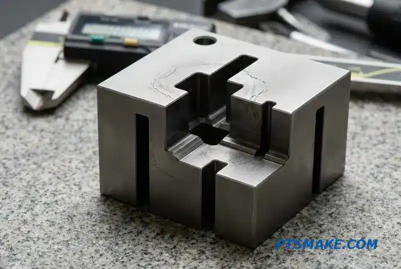
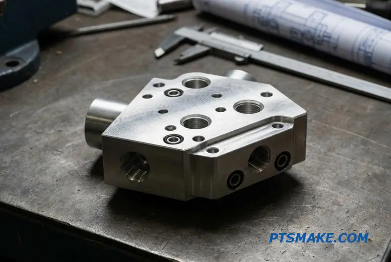
Hydraulic systems often fail not from a catastrophic breakdown, but from a tiny flaw. A single out-of-spec port, land, or sealing groove in a valve block can cause internal leakage, pressure loss, and ultimately, premature system failure. These CNC machined hydraulic valve blocks are the hidden chokepoint between your design and a leak-free machine.
What Defines Quality?
The difference between a reliable hydraulic valve block and a liability comes down to microns. The cost of a field failure—including downtime, teardown, and warranty claims—far outweighs the initial manufacturing investment. Precision is not optional.
Key Machining Tolerances
| Característica | Tolerancia Crítica | Impacto del error |
|---|---|---|
| Port Geometry | Profile ±0.02mm | Inefficient flow, pressure drop |
| Land Widths | Dimension ±0.01mm | Incorrect spool timing, internal leaks |
| Sealing Groove Depth | Depth ±0.015mm | O-ring failure, external leaks |
| Spool Bore Finish | Ra 0.2-0.4μm | Spool stiction, premature wear |
Only high-precision CNC machining can consistently hold these tolerances on a complex, multi-port block, ensuring your system performs as designed.
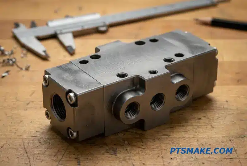
A common misconception is that all machining errors are equal. However, the type of error dictates the failure mode. A dimensional inaccuracy, such as an oversized spool bore, will cause an immediate and obvious leak. But a subtle error in surface finish can be far more insidious, leading to gradual performance degradation.
Beyond Dimensional Accuracy
Surface roughness inside a spool bore creates microscopic peaks and valleys. These imperfections disrupt the thin film of hydraulic fluid that lubricates the spool, causing accelerated wear on both the spool and the bore itself. This leads to a slow, internal leak that reduces the system’s eficiencia volumétrica1.
Error Type vs. System Consequence
| Machining Error | Efecto inmediato | Consecuencias a largo plazo |
|---|---|---|
| Incorrect Port Chamfer | Flujo turbulento | Energy Loss, Heat Generation |
| Poor Thread Quality | Riesgo de hilos cruzados | Catastrophic Fitting Blowout |
| Out-of-Spec Groove | Seal Extrusion | Gradual External Leak |
| Rugosidad superficial | Increased Friction | Component Wear, Reduced Lifespan |
This slow decline in performance is difficult to diagnose in the field. After collaborating with our clients, we found it often gets mistaken for pump wear or fluid contamination, leading to unnecessary and costly component replacements. The root cause, however, remains in the valve block itself.
Machining errors in hydraulic valve blocks are the direct cause of most leaks and system failures. Achieving critical tolerances for features like spool bores and sealing grooves is essential. Precision CNC machining is the only manufacturing process that can guarantee the reliability required for high-performance hydraulic systems.
Hydraulic Valve Block Materials — Aluminum vs Steel vs Stainless
Choosing the right material for hydraulic valve blocks is a critical first step. It directly impacts your system’s performance, lifespan, and overall cost. The decision isn’t just about strength; it involves balancing weight, corrosion resistance, and machinability for optimal results.
The Main Material Contenders
The primary options are aluminum, carbon steel, and stainless steel. Each material has distinct advantages that make it suitable for specific applications. My goal is to break down these differences from a practical perspective to guide your hydraulic valve block material selection.
Aluminum: The Lightweight Choice
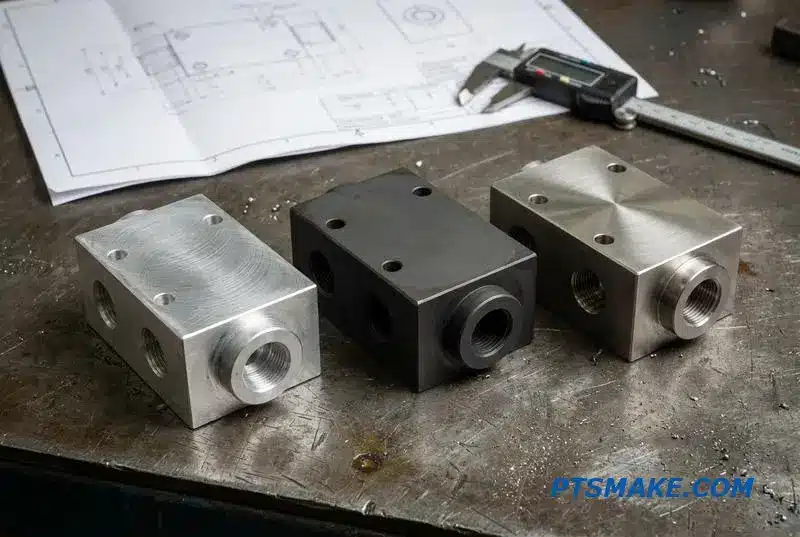
Aluminum 6061-T6 is excellent for mobile and industrial uses under 350 bar. Its light weight and superior machinability reduce both cycle times and costs. However, it’s softer and can be prone to port thread Galling2, a risk we mitigate with careful design and handling.
Carbon Steel: The High-Pressure Standard
For stationary systems exceeding 350 bar, carbon steels like 1045 or 4140 are the default choice. They offer superior strength and durability for demanding applications. A key consideration is that they require a protective surface treatment, such as phosphating or zinc plating, to prevent rust.
Stainless Steel: For Harsh Environments
When corrosion is the primary concern, such as in marine, food, or medical applications, stainless steel (304/316) is essential. While its corrosion resistance is unmatched, it is significantly tougher to machine, which translates to a higher manufacturing cost.
Material Selection at a Glance
| Application Pressure | Ciclo de trabajo | Medio ambiente | Material recomendado | Maquinabilidad | Coste relativo |
|---|---|---|---|---|---|
| < 350 bar | Intermittent / Continuous | Clean / Industrial | Aluminio 6061-T6 | Excelente | $ |
| > 350 bar | Continuous / Heavy | Industrial | Carbon Steel 1045/4140 | Bien | $$ |
| Cualquier | Continuo | Corrosive / Food-Grade | Stainless Steel 304/316 | Feria | $$$$ |
Your final choice balances pressure requirements, environmental exposure, and budget. Aluminum is ideal for lower-pressure, cost-sensitive projects. Steel is for high-pressure durability, while stainless steel is necessary for corrosive or sterile conditions. Proper material selection prevents costly failures down the line.
Key Dimensions That Decide Whether Your Valve Block Passes IQC
When a hydraulic valve block arrives for Incoming Quality Control (IQC), its success hinges on more than just appearance. Critical dimensions must be perfect. These measurements ensure the block functions reliably under pressure, preventing costly failures in the field.
Core Dimensional Checks
The inspection process focuses on specific geometric features. Each one plays a role in the valve’s overall performance, from sealing integrity to correct assembly. Poor control over any single dimension can compromise the entire hydraulic system.
Positional and Internal Accuracy
Precise location of ports and flawless internal passages are fundamental. We are not just making a block of metal; we are creating a precise fluid circuit.
| Dimension Checked | Tolerancia típica | Consecuencias del fracaso |
|---|---|---|
| Port Center Distance | ±0,05 mm | Manifold misalignment, connection stress |
| Bore Diameter (ID) | H7 or tighter | Internal leakage, poor spool response |
| Groove Depth/Width | ±0,05 mm | O-ring extrusion or damage |
| Surface Finish (Sealing) | Ra 0.8 µm | Fluid leaks, premature seal wear |
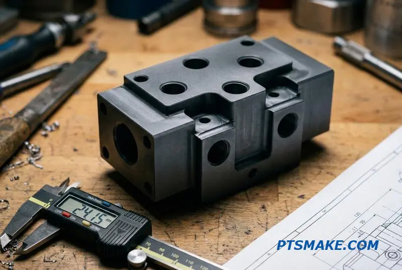
A quality engineer’s checklist goes deep into the functional geometry of the valve block. It’s about understanding why these numbers matter. For instance, a bore diameter that deviates from its H7 tolerance can cause internal cross-leakage, reducing the system’s efficiency and power.
Why Tolerances Are Not Negotiable
These are not just numbers on a drawing; they are critical functional requirements. A groove that is too tight will shear an O-ring during assembly, creating an immediate leak path. A groove that is too loose allows the O-ring to extrude under pressure, leading to eventual failure. The right hydraulic valve block machining tolerances son esenciales.
La ciencia detrás del acabado
Surface finish is another critical factor. A sealing face with a finish rougher than 0.8 Ra will create microscopic leak paths and rapidly wear out seals. The principles of tribología3 show us how surface interactions dictate friction, wear, and sealing life. Consistent, repeatable CNC machining is the only way to hold these tight tolerances run after run.
| Característica | Functional Impact of Poor Tolerance | Por qué es importante |
|---|---|---|
| Bore Roundness | Uneven spool wear, hydraulic lock | Ensures smooth, low-friction spool movement |
| Thread Pitch Diameter | Cross-threading, poor fitting seal | Guarantees secure and leak-free connections |
| Flatness (Mating Face) | Gasket failure, external leakage | Provides a uniform clamping surface for seals |
Precise dimensional control is crucial for hydraulic valve block performance. Tolerances for bores, grooves, and surfaces directly impact sealing, alignment, and reliability. This makes expert CNC machining not just a preference, but a necessity for dependable hydraulic systems.
Internal Cross-Drilling vs Machined Ports — The Manufacturing Reality
When designing hydraulic valve blocks, internal fluid routing is a critical detail. The choice between internal cross-drilling and machined ports directly impacts manufacturing complexity, cost, and ultimately, performance. It’s a decision that balances ideal fluid dynamics with practical manufacturability.
Straight Cross-Drills
This is the most common and simplest method. However, it often creates "dead-end" passages where drills intersect. These ends must be plugged, which can introduce potential leak points under high pressure or vibration.
Machined Channels
Milled channels offer more design freedom for complex circuits. However, they require cover plates to seal the passages. This adds components, assembly steps, and more potential sealing issues that need to be managed carefully.
| Método | Complejidad | Factor de coste |
|---|---|---|
| Perforación Transversal | Bajo-Medio | Bajo |
| Milled Channels | Alta | Alta |
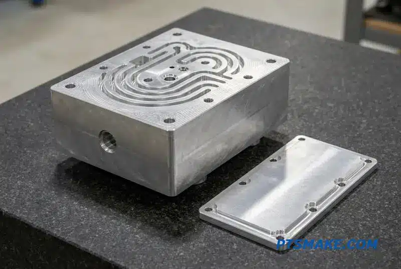
Manufacturing Trade-offs
The reality of hydraulic valve block cross drilling is managing compromises. While cost-effective, straight cross-drills leave "dead legs" that require plugs. These plugs become a potential failure point, especially under high-pressure cycles or when using thinner fluids.
For long, straight passages, we often use gun-drilling. It maintains high precision over extreme depths but requires specialized equipment. This makes it more expensive than standard drilling but is necessary for certain hydraulic valve blocks that demand long, uninterrupted internal circuits.
Risks and Specifications
Milled channels, sealed with a cover plate, provide design flexibility but increase component count and sealing faces. Any imperfection in the sealing surface can lead to leaks. Abrupt geometric changes in drilled passages can also cause issues like Cavitación4, damaging the block over time.
| Característica | Cross-Drill | Gun-Drill | Milled Channel |
|---|---|---|---|
| Mejor uso | Simple, short connections | Long, straight passages | Complex, non-linear paths |
| Key Risk | Internal burrs, plug leaks | Higher machining cost | Gasket or seal failure |
| Coste | Bajo | Medio | Alta |
When specifying internal passages, be clear. Ask us at PTSMAKE about our maximum depth-to-diameter ratio and our internal deburring processes. This communication is crucial for reliable performance.
Ultimately, the choice of internal passage is a balance of design needs, manufacturing cost, and acceptable risk. Clear specifications and open communication with your manufacturing partner are essential for creating reliable and efficient hydraulic valve blocks that perform as intended.
Thread Types and Port Standards You Must Specify Correctly
Choosing the right thread for hydraulic valve blocks is critical. A small mistake on a drawing can lead to significant leaks, costly rework, or even complete part failure. I’ve seen incorrect specifications cause major project delays. The key is understanding how different standards seal.
Sealing Mechanisms: The Core Difference
There are two primary ways a port thread creates a seal. It either seals on the threads themselves or on a separate surface, typically using an O-ring. This choice impacts pressure rating, reusability, and reliability. Mismatched components will never seal properly.
Common Port Thread Standards
To avoid these issues, it’s essential to be familiar with the most common standards used globally. Each has a specific geometry and sealing method. Specifying the wrong one is a common and expensive error.
Quick Comparison of Major Standards
Here is a table summarizing the standards we frequently machine at PTSMAKE. This helps our clients select the best fit for their application.
| Estándar | Thread Geometry | Método de sellado | Rango de presión típico | Common Regions |
|---|---|---|---|---|
| SAE J1926 | Straight (UN/UNF) | O-ring on Boss | Alta | Norteamérica |
| BSPP (G) | En paralelo | O-ring/Washer on Land | Media a alta | Europa, Asia |
| BSPT (R) | Cónico | On the Threads | Bajo a medio | Europa, Asia |
| NPT/NPTF | Cónico | On the Threads | Bajo a medio | Norteamérica |
| Metric Taper | Cónico | On the Threads | Bajo a medio | Europa |
| Metric Parallel | En paralelo | O-ring/Washer on Land | Alta | Europe, Global |
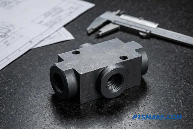
Understanding the distinction between sealing methods is crucial for designing reliable hydraulic valve blocks. Tapered threads, like NPT and BSPT, create a seal through thread deformation. As the male and female ends are tightened, their threads wedge together, forming a metal-to-metal seal.
The Problem with Tapered Threads
This method, known as an interference fit, has drawbacks. It is prone to leakage at high pressures and is not ideal for systems with high vibration. Furthermore, thread sealants are almost always required. Over-tightening can crack the port, destroying an expensive hydraulic valve block.
The Advantage of Parallel Threads with O-Rings
In contrast, parallel threads like SAE J1926 and BSPP use an O-ring. The threads provide clamping force, but the seal is created by compressing the O-ring against a surface. This design offers superior sealing for high-pressure applications and allows for repeated assembly and disassembly without damaging the port. The material’s long-term behavior under compression, or Creep5, is a factor here, but the design is generally more robust.
Your Drawing Specification
On your technical drawing, you must clearly define the thread standard and the port geometry. For O-ring boss ports, this includes specifying the spotface or chamfer diameter and depth. Ambiguity here forces us to stop and ask for clarification, delaying production.
Correctly specifying thread standards like SAE or BSPP is crucial for your hydraulic valve blocks. The sealing method—thread deformation versus O-ring compression—directly impacts performance, pressure rating, and reusability. A clear drawing prevents costly leaks and production delays.
Cross-Spools and Bore Finish — What You Can’t Control Without the Right Machining
The performance of hydraulic valve blocks hinges on the microscopic details of the spool bore. This is where the valve spool slides, controlling fluid flow. An imprecise bore finish leads to internal leakage, erratic control, and eventual failure. The right machining is not a luxury; it’s a fundamental requirement.
The Challenge of Bore Geometry
For proportional and servo valves, control is everything. This requires a spool bore with exceptional roundness and straightness. Even slight deviations can cause the spool to bind or wear unevenly, compromising the entire hydraulic system’s stability and responsiveness.
Surface Finish: The Deciding Factor
Surface finish, measured in Ra, dictates how smoothly the spool moves and how well it seals. A rough surface creates friction and allows fluid to bypass the spool, reducing efficiency.
| Característica | Poor Machining | Mecanizado de precisión |
|---|---|---|
| Redondez | Oval or irregular | Sub-micron accuracy |
| Rectitud | Tapered or bowed | Consistent diameter |
| Acabado superficial | >1.6 Ra (Rough) | 0.4-0.8 Ra (Smooth) |
| Resultado | Leakage, wear, instability | Precise control, long life |
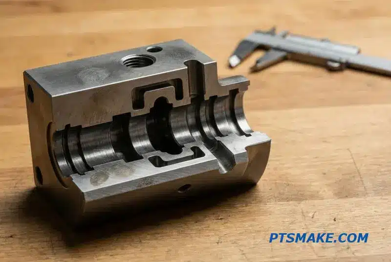
Achieving the necessary geometry for a spool bore is a multi-stage process. It begins with high-precision CNC machining, which is essential for establishing the foundational straightness and roundness. For high-performance hydraulic valve blocks, this initial step must hold tolerances that many shops simply cannot meet.
Achieving Sub-Micron Finishes
Our process targets a surface finish between 0.4 and 0.8 Ra for most proportional valve applications. This smooth surface minimizes friction and prevents leakage. After our research with clients, we confirmed this range provides the best balance between performance and manufacturing feasibility. This level of hydraulic valve block spool bore machining is our standard.
The Role of Honing
For the most demanding servo valves, CNC machining alone is not enough. We use honing as a secondary operation. Honing uses abrasive stones to achieve an even finer surface finish and perfect the bore’s cylindrical geometry. Not every CNC shop invests in honing equipment and expertise because it requires a specialized skill set.
Choosing a supplier without this capability is a significant risk. If they cannot hold the required spool-bore geometry, you face issues like valve instability or the dreaded Stick-slip phenomenon6. This leads to unpredictable performance and premature system wear, ultimately costing you more in the long run.
The precision of spool bore machining directly impacts valve control, leakage, and lifespan. Choosing a partner with advanced CNC and honing capabilities is critical to avoid instability, internal leakage, and premature wear in your hydraulic valve blocks, ensuring long-term system reliability.
Sealing — O-Ring Grooves, Gasket Faces, and Why Leaks Happen at the Joints
The success of any hydraulic system often comes down to millimeters of machined metal. Leaks almost always start at the joints, specifically at the sealing surfaces. These critical areas, such as O-ring grooves and gasket faces, are where precision matters most.
The Foundation of a Good Seal
An O-ring needs a precisely engineered home to work effectively. We follow standards like AS568 for sizing, but the real challenge is machining the groove. A small deviation in depth can ruin the seal. A shallow groove crushes the O-ring, while a deep one prevents proper compression.
Machining for Zero Leaks
The flatness and surface finish of a gasket face are just as critical. A seemingly smooth surface can have microscopic peaks and valleys, known as asperidades7, creating tiny paths for fluid to escape under pressure. Achieving a mirror-like finish without tool chatter requires immense control.
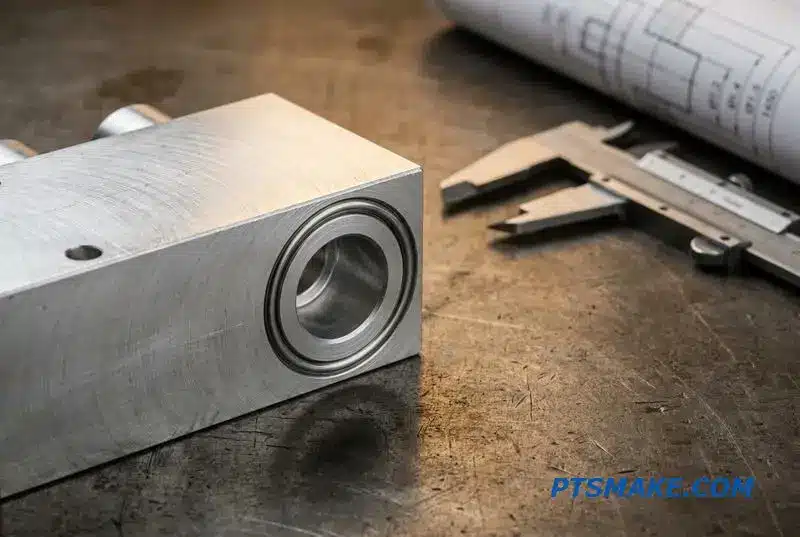
In machining hydraulic valve blocks, the sealing surfaces are non-negotiable. The goal is to create a perfect interface where the seal can do its job without interference from the metal itself. This requires a deep understanding of both design intent and machining capability.
O-Ring Groove and Face Tolerances
The most important specification is the hydraulic valve block O-ring groove tolerance. We typically hold groove depth within ±0.05mm. Any more variation compromises the seal’s compression ratio. Likewise, the surface finish on sealing faces is crucial; we aim for a smoothness of Ra 0.8μm or better.
Common Leak Causes
Leaks are rarely caused by a faulty seal alone. More often, the machining of the housing is the root cause. Here are the most common failures I’ve seen.
| Problema | Consecuencia |
|---|---|
| Groove Too Deep/Wide | Insufficient O-ring compression, allowing fluid bypass. |
| Groove Too Shallow/Narrow | The O-ring is pinched or extruded, leading to damage. |
| Rough Sealing Face | Creates micro-leakage paths that grow over time. |
| Scratches or Burrs | A single scratch across a sealing face can cut the O-ring. |
Drawing Verification Checklist
Before sending a design for quotation, verify these points:
- All O-ring groove dimensions match the seal manufacturer’s standard.
- Surface finish requirements for all sealing faces are clearly specified.
- Tolerances for groove depth and width are explicitly stated.
- Material callout is appropriate for the fluid and pressure.
Properly defining these features on the drawing is the first step to a leak-free product.
Successful sealing relies on a partnership between design and manufacturing. Precise groove dimensions and a flawless surface finish are essential. Without them, even the best O-ring or gasket will fail, causing leaks at the joint.
The Cost Drivers in Valve Block Machining — What Actually Raises Your Price
When you receive a quote for custom Hydraulic Valve Blocks, the price can often seem high. The cost isn’t just in the material; it’s driven by the complexity of the machining operations required to create the final part. Every feature adds time and tooling.
Material Selection and Complexity
The choice of material sets the baseline cost. Aluminum is generally the most economical, while stainless steel and other alloys are more expensive. The number of ports and internal passages also significantly increases machine time, adding to the final price.
Precision and Finishing
Tolerances and surface finish requirements are critical cost factors. Tighter specifications demand more precise machining, longer inspection times, and potentially specialized secondary operations.
| Costes | Impacto en el precio | Razón principal |
|---|---|---|
| Tolerancias estrictas | Alta | Slower machine speeds, increased inspection time |
| Internal Cross-Drills | Alta | Requires specialized tooling and complex deburring |
| Number of Ports | Medio-Alto | More machine setups and tool changes |
| Material (Steel vs. Al) | Medio | Higher raw material cost, slower machining |
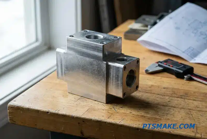
Let’s delve deeper into what drives the hydraulic valve block machining cost. Intricate internal cross-drilling is one of the biggest factors. These deep, intersecting passages often require specialized gun drilling and meticulous deburring, which are both slow and labor-intensive processes.
Equilibrando Precisión y Costo
Tight tolerances are essential for sealing surfaces and spool bores, but applying them to non-critical features is a common mistake. Based on our experience at PTSMAKE, relaxing tolerances on features like external dimensions can reduce machining and inspection time, lowering costs without impacting performance.
Consideraciones sobre el acabado superficial
A smooth surface finish is often required for sealing. However, achieving a very low Ra value involves secondary processes like honing or lapping. The orientation of the surface pattern, or its Orientación8, can be just as important for function, but specifying it adds complexity.
Smart Design for Manufacturing
You can actively reduce costs. Consolidate ports where possible, use standard thread sizes to avoid custom tooling, and minimize deep cross-drilled holes. Committing to a reasonable batch quantity also helps, as it allows setup costs to be amortized over more parts.
| Cost Reduction Tactic | Ahorro potencial |
|---|---|
| Relax Non-Critical Tolerances | Alta |
| Consolidate Ports & Features | Medio |
| Use Standard Thread Sizes | Medio |
| Increase Order Quantity | Medio-Bajo |
The final cost of your valve block is directly linked to its design complexity. By focusing on manufacturability—simplifying features, relaxing unnecessary tolerances, and selecting standard components—you can achieve significant cost savings without compromising the part’s essential function.
Prototype vs Production Valve Blocks — What Changes Between 5 and 500 Pieces
The journey from a single prototype hydraulic valve block to a production run of 500 involves a fundamental shift in manufacturing strategy. What works for a few pieces often fails at scale. The initial focus on speed and design verification gives way to an intense focus on repeatability, efficiency, and cost per unit.
Prototyping: The Priority is Speed
For a small batch of 1-5 pieces, the goal is to get a functional part quickly. A machinist can often use a single setup with minimal custom tooling. This approach offers maximum flexibility for design changes but results in a higher cost per individual part.
Production: The Priority is Consistency
Scaling up to 500 pieces demands a different mindset. The process must be repeatable and cost-effective.
| Escenario | Prototyping (1-5 pcs) | Production (50-500+ pcs) |
|---|---|---|
| Configurar | Single, flexible setup | Optimized multi-fixture setups |
| Herramientas | Standard, minimal | Utillaje y utillaje a medida |
| Inspección | Manual, first-off inspection | In-process gauging, batch inspection |
| Coste | Coste por unidad elevado | Menor coste por unidad |
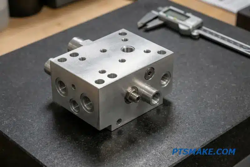
Scaling hydraulic valve block manufacturing requires careful planning to avoid common pitfalls. A design that is easily machined as a one-off prototype can become incredibly expensive or even impossible to produce in large volumes. This is a classic trap I’ve seen many times.
The Prototype-to-Production Pitfall
The primary issue is that prototype methods don’t scale. A complex internal passage drilled manually on a prototype becomes a major bottleneck in production. It may require specialized tooling or multiple operations, driving up cycle time and cost significantly. This is where Design for Manufacturability (DFM) becomes critical.
Optimizing for Scale
For production runs, we shift to multi-fixture machining, allowing us to work on several parts simultaneously. Process validation and in-process gauging become standard to ensure every part meets spec without constant manual checks. We also apply Dimensionado geométrico y tolerancias (GD&T)9 rigorously to define acceptable variation, ensuring interchangeability and function across the entire batch. At PTSMAKE, we always encourage a DFM review early in the process.
| Consideración | Prototyping Impact | Impacto en la producción |
|---|---|---|
| Tolerancias estrictas | Achievable but slow | Requires process control, drives cost |
| Complex Ports | Feasible with manual setup | May require special tools or fixtures |
| Elección del material | Based on performance | Balance of performance and machinability |
| Acabado superficial | Achieved with extra passes | Requires specific tools and processes |
Successfully transitioning from prototype to production hinges on early planning. A design optimized for manufacturing from the start ensures a smooth, cost-effective scaling process, avoiding costly redesigns and delays when moving from 5 to 500 pieces.
Design for Machinability — Valve Block Changes That Save You Money
Optimizing hydraulic valve block design for manufacturing isn’t about compromising performance; it’s about eliminating unnecessary costs. Small geometric changes can significantly reduce machine time and tooling complexity. This directly translates into lower part costs and faster delivery for your projects.
Key DFM Principles
Thoughtful design choices are crucial. Prioritizing standard features and realistic tolerances on non-critical surfaces simplifies the entire production process. Focusing on these areas early in the design stage yields the best results for your budget and timeline.
| Costly Feature | DFM Alternative |
|---|---|
| Many unique drill sizes | Standardize to fewer sizes |
| Deep, small-diameter holes | Optimize port layout to reduce depth |
| Tight non-sealing tolerances | Specify looser, functional tolerances |
| Angled cross-drilling | Use 90-degree drilling where possible |
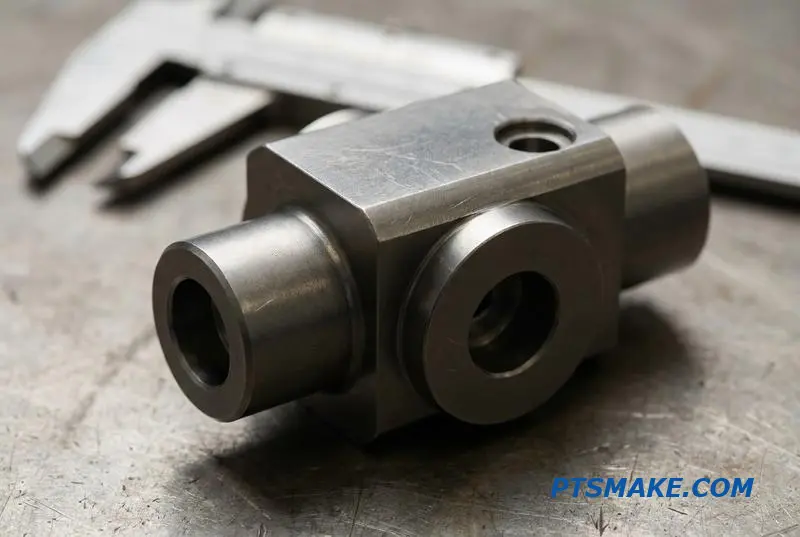
A Collaborative Approach to Savings
Effective DFM is a conversation, not a set of commands. When designers and machinists collaborate, we unlock cost savings that neither could achieve alone. At PTSMAKE, we encourage this partnership to find the most efficient manufacturing path for your hydraulic valve blocks.
The Machinist’s Perspective
From my view, complexity equals time and risk. For example, avoiding ultra-deep holes minimizes tool breakage and cycle time. Likewise, maintaining adequate wall thickness between ports prevents material distortion and ensures structural integrity, reducing scrap rates and potential failures.
From Complex to Cost-Effective
Consider two versions of the same valve block. The first has numerous unique thread sizes and very deep cross-drilled holes. The second standardizes threads and re-routes internal channels to allow for shallower, orthogonal drilling. Our tests show the second design can be 20-30% cheaper to produce due to reduced setup and machine time. The material’s Anisótropo10 properties can also affect drilling accuracy in deep holes.
| Elección del diseño | Impacto en los costes |
|---|---|
| Non-standard tool sizes | High (Custom tooling) |
| Standardized tooling | Low (Faster setup) |
| Multiple setups for angles | High (Increased labor) |
| 90-degree drilling | Low (Simplified process) |
Smart DFM choices in hydraulic valve block design directly lower manufacturing costs. Collaboration with your machining partner, like PTSMAKE, is the fastest way to identify and implement these savings for your project without sacrificing quality or performance.
Surface Finish Options for Valve Blocks — Anodizing, Phosphate, and Beyond
Choosing the right surface finish for valve blocks is as critical as the machining itself. It’s not just about aesthetics; it’s about performance, corrosion resistance, and lifespan. The material of your hydraulic valve block dictates the best options available.
Aluminum Finishes
For aluminum blocks, anodizing is a common choice. It enhances corrosion resistance and provides a harder surface. For steel components, treatments like phosphating offer basic protection, while plating provides a more robust barrier against harsh environments. Each finish impacts final dimensions.
Steel and Stainless Options
Understanding these effects is crucial. A finish applied incorrectly can ruin a perfectly machined part by altering critical tolerances. We must account for this during the design and machining phases to ensure the final product meets exact specifications.
| Material | Common Finish | Beneficio principal | Impacto dimensional |
|---|---|---|---|
| Aluminio | Anodizado | Wear & Corrosion Resistance | Añade grosor |
| Aluminio | Revestimiento de conversión | Resistencia a la corrosión | Mínimo |
| Acero | Fosfatado | Light Rust Protection | Mínimo |
| Acero | Plating (Zinc/Nickel) | Resistencia superior a la corrosión | Añade grosor |
| Acero inoxidable | Pasivación | Removes Contaminants | Ninguno |
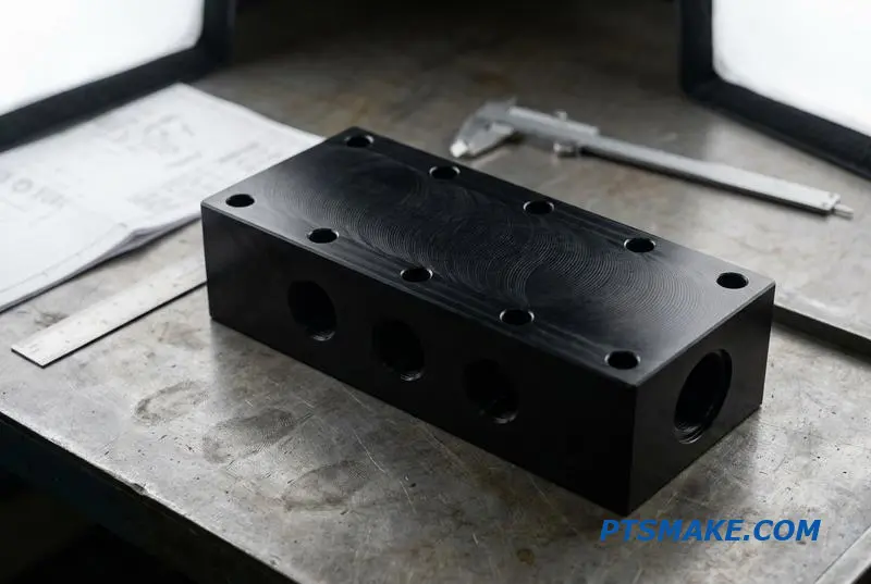
A Closer Look at Aluminum Treatments
For aluminum valve blocks, we often recommend anodizing. Standard clear or black anodize (Type II) is excellent for corrosion protection. Hard anodize (Type III) creates a much thicker, ceramic-like layer that significantly improves wear resistance, which is ideal for high-cycle applications.
However, anodizing adds material. A Type III coating can add over 0.002 inches. We must factor this into our CNC programming, adjusting dimensions beforehand to ensure bores and threads are within tolerance after finishing. Conversion coating is a thinner, cheaper alternative offering good corrosion resistance but minimal wear protection.
Finishes for Steel and Stainless Steel
When working with carbon steel, phosphating is a cost-effective choice for light rust prevention, especially if the part will be oiled in service. For more demanding environments, zinc or nickel plating provides a much more durable barrier. Plating build-up, however, can be an issue on threads.
We manage this by either machining the threads slightly undersized or by masking them during the plating process. For stainless steel, no coating is typically needed. Instead, the proper hydraulic valve block surface finish is pasivación11. This is a chemical cleaning process that removes free iron and contaminants from the surface, enhancing the material’s natural corrosion resistance without changing dimensions.
Choosing the correct finish requires balancing cost, performance, and material properties. It’s a critical step that ensures the valve block functions reliably for its intended lifespan, and at PTSMAKE, we guide our clients through these decisions to prevent costly errors.
Selecting the right surface finish is a crucial step. It directly impacts the valve block’s durability, corrosion resistance, and dimensional accuracy. This decision requires a careful balance between material, application environment, and final tolerance requirements to ensure optimal performance and longevity.
Building a Long-Term Valve Block Supply — Why Repeatability Beats a One-Off Deal
When sourcing hydraulic valve blocks, viewing the decision as a simple purchase is a mistake. You’re not just buying a part; you are establishing a supply chain link. The real value lies in finding a partner who delivers consistent quality over time.
The True Cost of a One-Off Deal
Focusing solely on the lowest price for a single order often ignores long-term costs. A cheaper, one-time supplier might lack the process control needed for future batches, leading to inconsistencies that disrupt your assembly line and final product performance.
Why Consistency is King
For a component used across multiple machines, repeatability is non-negotiable. It ensures every valve block fits and functions identically. This predictability is the foundation of a reliable product and an efficient manufacturing operation, saving you time and resources down the line.
| Aspecto | One-Off Supplier | Long-Term Partner |
|---|---|---|
| Enfoque | Lowest Initial Price | Coste total de propiedad |
| Proceso | Inconsistent/Undocumented | Repeatable & Validated |
| Calidad | Variable Batch-to-Batch | Consistent Tolerances |
| Relación | Transaccional | Collaborative |
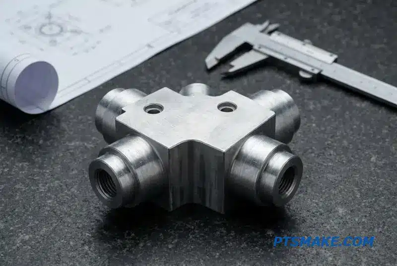
Establishing a Repeatable Process
For medium-volume orders, typically 500 to 2,000 pieces, a supplier’s ability to establish a repeatable process is paramount. This is where a true valve block machining production partner proves their worth. It moves beyond simply making a part to engineering a production system.
The Hallmarks of a Reliable Partner
A dedicated partner invests in a system that guarantees consistency. This includes consistent tolerances batch after batch, uniform surface finishes, and complete, documented traceability for every unit produced. They don’t just follow a drawing; they understand its intent and learn your design’s nuances over time.
Más allá de la Cotización
We’ve found that material properties are critical for repeatable results. A material that is largely Isótropo12 will machine more predictably than one with directional grain structures. A good partner will understand and control for these variables. This knowledge separates a simple machine shop from a manufacturing partner.
Evaluating a potential supplier requires looking beyond the price. Ask for evidence of their processes and quality control.
| Criterios de evaluación | En qué fijarse |
|---|---|
| Documentación de procesos | Clear work instructions, SPC charts |
| Quality Reports | CMM inspection reports, material certs |
| Comunicación | Proactive updates, technical clarity |
| Trial Orders | Consistency between initial samples and small batches |
The practical next step is clear: send a complete drawing with clear tolerances. Evaluate the supplier on the evidence they provide—their reports, certifications, and communication—rather than just a single number on a quote.
Choosing a valve block supplier is an investment in your production line’s stability. Prioritize a partner who demonstrates a repeatable manufacturing process, backed by clear evidence and communication, to ensure long-term success over a short-term saving.

Discover how this metric directly impacts your hydraulic system’s power output and operational costs. ↩
Understanding this wear mechanism is crucial for designing reliable threaded connections and preventing premature system failure. ↩
Understanding this field helps diagnose wear, friction, and sealing issues in hydraulic systems. ↩
Understanding this phenomenon helps prevent component damage and system inefficiencies in hydraulic circuits. ↩
Understanding creep helps predict how seals behave under long-term pressure and temperature, preventing future leaks. ↩
Learn how this phenomenon causes jerky motion, affecting the precision control of hydraulic machinery. ↩
Learn how microscopic surface texture directly impacts fluid dynamics and sealing effectiveness. ↩
Understanding this concept helps in specifying functional surfaces for better sealing performance. ↩
Learn how GD&T provides a universal language for defining and controlling part features in mass production. ↩
Understanding this property helps predict material behavior during precision drilling. ↩
Understanding this process is key to maximizing the natural corrosion resistance of stainless steel. ↩
Understanding this property helps predict material behavior during machining, ensuring part uniformity across large production runs. ↩