
Swiss Machining Service for Precision Parts
Small, complex parts made to your drawings. PTSMAKE provides Swiss machining for precision connectors, fluid fittings, valve components and other detailed turned parts, from prototypes to production orders.
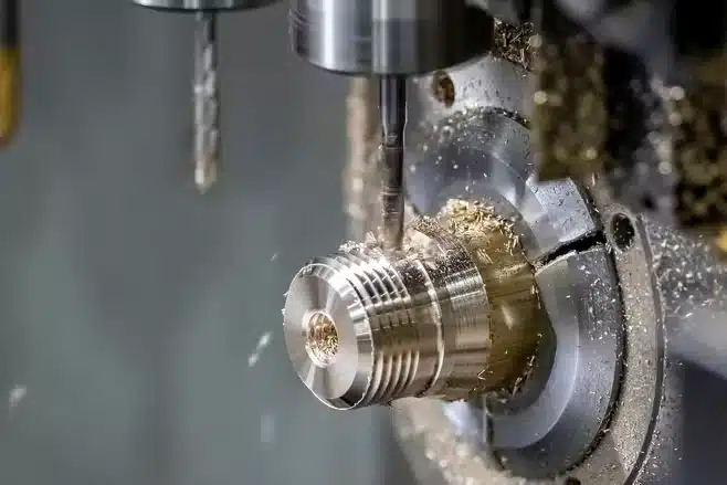
- Ø0.5–32 mmBar diameter range
- 1–200 mmPart length range
- ±0,005 mmOn suitable dimensional features
- Metal & PlasticMaterial grade reviewed for your part
Diameter, length and tolerance are reviewed together with material and geometry. These ranges do not apply to every combination; final feasibility and dimensional tolerances are confirmed from your drawing.
Why Choose PTSMAKE for Swiss Machining?
Bring the features that make your part difficult: a slender profile, close fits, cross holes or several operations on a small component.
Support for Slender Parts
Swiss guide-bushing support keeps cutting close to the supported bar, helping control deflection on small, slender features.
Review Your Part ShapeComplex Feature Relationships
Review diameters, threads, flats and side holes together, so the machining sequence supports the fits your assembly needs.
Discuss Critical FeaturesMaterial Choices for Function
Choose from stainless steel, brass, aluminum, titanium, alloy steel and selected engineering plastics, with the grade matched to the application.
Discuss Your MaterialPrototypes Through Production
Start with a prototype and discuss follow-on quantities. Order minimums and setup costs are assessed for the individual part.
Planifiez votre commandeQuality Control for Swiss Machined Parts
A correct diameter is one part of a working fit. Define feature relationships, edge condition and finished surfaces alongside dimensional limits.
| Critical feature | Define on the drawing | Inspection to agree |
|---|---|---|
| Fits & small diameters | Individual limits and material condition | Measurement method, access and reporting points |
| Long or stepped profiles | Datums, straightness and runout where functional | Support arrangement and checks along the part |
| Threads & cross holes | Thread specification, feature positions and edge requirements | Thread checks and examination of hole intersections |
| Sealing & plated surfaces | Roughness and dimensions in the finished condition | Final surface checks and the records required |
Dimensional tolerances as tight as ±0.005 mm on suitable features, subject to drawing and material review. Runout, straightness, roundness and surface roughness require separate specifications.
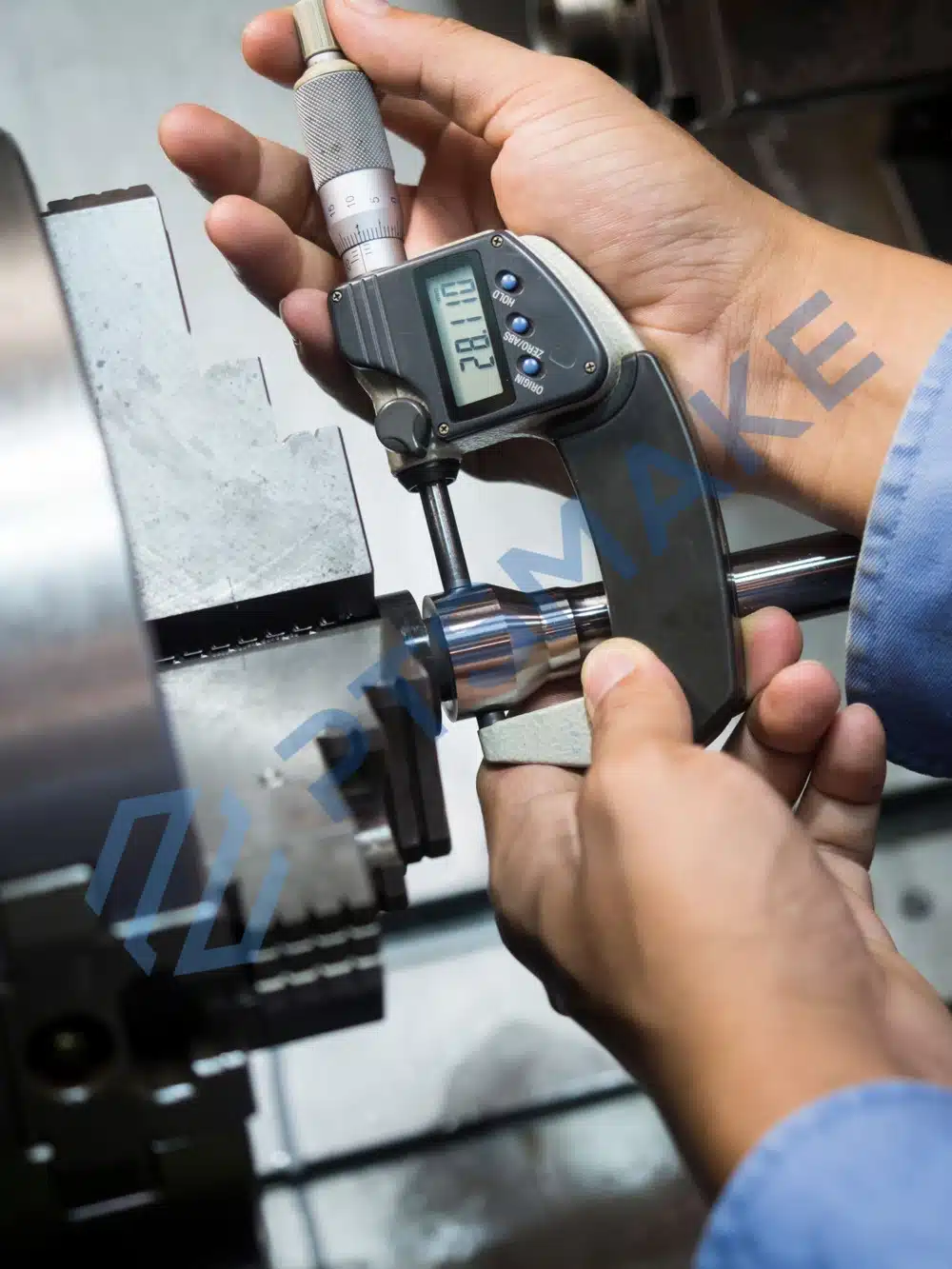
Include any material certificates, dimensional reports or first-article format you need in the RFQ. Confirm the available documents, inspection methods and sampling with us before ordering.
Materials for Swiss Machined Parts
The exact grade matters, especially for small holes, thin sections and demanding surface finishes. Start with the part’s working environment and required material condition.
Acier inoxydable
- Common grades
- 303, 304 and 316; other grades by review.
- Swiss machining consideration
- Balance corrosion requirements with machinability, chip control and the finish on small features.
Identify wetted surfaces and any passivation specification.
Quote Your Stainless Steel Part →Laiton
- Typical uses
- Connectors, contacts and small fluid fittings.
- Swiss machining consideration
- Choose the exact alloy for conductivity, strength, corrosion exposure and fine thread requirements.
Specify any lead-content restriction and required plating.
Quote Your Brass Part →Alliages d'aluminium
- Typical uses
- Lightweight connectors, fittings and instrument components.
- Swiss machining consideration
- Thin walls, burr control and surface protection need attention on small, detailed parts.
State the alloy, temper and dimensions required after finishing.
Quote Your Aluminum Part →Alliages de titane
- Typical uses
- Small parts needing a combination of strength, low weight and corrosion resistance.
- Swiss machining consideration
- Slender sections, heat and chip evacuation can affect the achievable geometry and cycle time.
Send the grade and material specification with the drawing.
Quote Your Titanium Part →Acier allié
- Typical uses
- Loaded shafts, pins and wear-sensitive mechanical components.
- Swiss machining consideration
- Hardness and heat-treatment sequence affect cutting, distortion and final dimensional control.
Define the supply condition and required final hardness.
Quote Your Alloy Steel Part →Plastiques techniques
- Selected grades by review
- Parts requiring insulation, low weight or low-friction contact.
- Swiss machining consideration
- Thermal movement and clamping can change small diameters or deform thin walls.
Include the exact polymer grade, service temperature and fit limits.
Review Your Plastic Part →Surface Finishes for Swiss Machined Parts
Specify the finish by functional surface. The options below are starting points for review; compatibility and availability are confirmed for your material and geometry.
| Part requirement | Option to discuss | Detail that affects the result |
|---|---|---|
| General machined surfaces | As-machined finish with defined edge treatment | Roughness, tool marks and the permitted edge break; identify sharp metering edges separately. |
| Stainless surfaces | Passivation | Material grade, applicable specification and cleaning of small holes and internal passages. |
| Aluminum protection | Anodisation | Finish type, color and masking of threads or close fits; specify acceptance after finishing. |
| Corrosion, wear or contact surfaces | Suitable plating | Coating type and thickness, internal coverage and the dimensions needed on the finished part. |
| Precision sealing or sliding fits | Local polishing or an additional finishing operation | Agree feasibility, edge preservation, roughness and the final dimensional limits. |
Swiss Machining Production Lead Times
Setup and process adjustment matter for Swiss parts. Plan complex prototypes separately from simple urgent samples.
Simple Urgent Prototypes
1–3 days**Possible for selected simple parts with material in stock, after feasibility and scheduling review. Complex Swiss prototypes are quoted individually.
Small Batches
7 à 15 joursA typical planning range, subject to part complexity, material, finish and the agreed inspection requirements.
Tirages de la production
15 à 30 joursPlan the order quantity and any repeat releases alongside setup, finishing and inspection.
Final production lead time is confirmed with your quote. Send your required date and prototype or production quantities together.
Design Choices That Can Lower Swiss Machining Costs
Keep the features your assembly needs, and simplify the machining and inspection around them.
Focus Tight Tolerances on Fits
Apply tight diameter limits to functional journals. Use agreed general tolerances elsewhere, while keeping the geometry and surface requirements your assembly needs.
Shorten Unneeded Slender Sections
Reduce unsupported slender length where function allows. Review support through the cutting sequence; total part length alone does not determine machining stability.
Use Practical Hole Sizes and Depths
Choose standard drill sizes when function permits. Specify the required full-diameter depth and allow for the drill point, avoiding unnecessary drilling and chip-removal time.
Define Cross-Hole Edge Requirements
Identify internal burr limits and acceptable edge breaks before quoting. Preserve sealing lands and flow features so deburring does not alter the part’s function.
Vous approuvez toute modification de dessin avant la production.
Swiss Part Design Examples
Review the surfaces and feature relationships that make a small component work in its assembly.
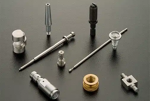
Fluid Fittings & Metering Components
Small fluid components bring together bores, threads, shoulders and sealing surfaces. A close diameter alone does not define how the finished assembly will fit or seal.
- Dimension the bore and mating surface in their final condition.
- Identify functional edges that must stay sharp, and hole intersections that need burr removal.
- Specify the thread form, sealing arrangement and finish requirements separately.
Review pressure, material and cleanliness requirements with the drawing; geometry alone cannot establish suitability.
Review Your Next Swiss Machining Project
Share the features that control fit, sealing or assembly. Include the prototype quantity and your expected production demand.
Starting Your Swiss Machining Order
What should I send for a quotation?
Send your latest 2D drawing and 3D model, material grade and condition, quantities, finish, critical tolerances and required date. Include inspection or documentation requirements and the delivery destination.
Do you accept prototypes, and is there a minimum order?
Yes, we accept prototype orders. The minimum order depends on complexity and setup cost; prototype quantities can be discussed individually. Send both the initial quantity and expected repeat demand.
What size parts can PTSMAKE review for Swiss machining?
Our Swiss machining range covers bar diameters of Ø0.5–32 mm and part lengths of 1–200 mm. The workable combination depends on material, geometry, support and tolerances. These limits do not mean every diameter can be combined with the maximum length.
Can you hold ±0.005 mm tolerances?
Yes, on suitable dimensional features, subject to drawing and material review. This is not a general limit for runout, straightness, roundness or every feature on the part. Specify those requirements individually.
Can I get an urgent prototype in 1–3 days?
It may be possible for selected simple parts with material in stock, after review. Complex Swiss parts generally need more preparation and process adjustment, so prototype timing is quoted individually. Small batches typically take 7–15 days and production runs 15–30 days, with final timing confirmed in the quote.
Can I request material and inspection records?
Yes—include the required records, format, sampling and acceptance criteria in your RFQ. Confirm with us which documents and measurement methods can be supplied for the specific order before placing it.
Will design changes be made without my approval?
Any proposed drawing change is for your review and approval before production. Identify the features that must remain unchanged so cost discussions preserve the part’s function.
A Buyer’s Guide to Swiss Machining
Make the decisions that matter for small precision parts: the machining route, supported geometry, functional tolerances, material condition and a clear path from quotation to production.
1. When Is Swiss Machining a Better Fit Than Conventional Turning?
Swiss machining is worth evaluating when a small part combines slender sections with several precision features. In a guide-bush setup, the sliding headstock feeds bar through support close to the cutting area. This helps limit workpiece deflection. Conventional turning holds the workpiece in a chuck or collet and can also use additional support. The best route depends on the complete geometry and order, rather than the process name alone.
A stepped connector contact with a narrow tip, a threaded section and a side feature presents a different problem from a short, thick spacer. The first part may benefit from the support and combined operations available on a suitable Swiss setup. The spacer may be economical with conventional CNC turning. These are process-selection examples; a short part is not automatically unsuitable for Swiss machining.
| Part requirement | What to compare |
|---|---|
| Small diameter with a slender working section | Support near the cut, access to each feature and handling after machining |
| Turned body with cross holes, flats or end features | Operations possible in the proposed setup and any secondary work |
| Short, rigid part with few features | Swiss and conventional turning setup costs at the actual quantity |
| Large non-round features or substantial pockets | Turning combined with milling, or a different starting form |
Ask which features will share a setup and which require another operation. Fewer transfers can reduce handling and simplify some feature relationships, but they do not establish finished accuracy by themselves. Tool access, grip length and the inspection method still need review. PTSMAKE can assess your complete model and drawing to determine a suitable route; do not simplify the drawing to show only the features you expect a Swiss machine to make.
2. How Do Diameter, Length and Support Affect Feasibility?
PTSMAKE’s Swiss machining range covers bar diameters of 0.5–32 mm et part lengths of 1–200 mm. The workable diameter and length combination depends on material, geometry, support and tolerances. A 0.5 mm bar and a 200 mm finished length require a very different assessment from a thicker, rigid part; the stated ranges do not guarantee every combination.
Bar diameter also differs from finished feature diameter. A part with a wide head and a slender stem must start from stock large enough for the head, with appropriate machining allowance. The supplier then needs to consider how material is supported as the stem is cut and how the finished section will be held or collected. A maximum outside diameter alone leaves these questions unanswered.
Identify the thinnest section, the length of each slender section, wall thickness and the locations of holes or grooves that weaken it. Overall length-to-diameter ratio is a useful warning sign, but the locally unsupported section often matters more. A short, reduced-diameter neck may be the most sensitive feature on an otherwise substantial component.
- Working support: show shoulders, reduced diameters and features that affect how the part can be supported during each cut.
- Holding surfaces: identify whether grip marks are permitted and which areas must remain untouched.
- Released condition: specify relevant straightness, form and fit requirements for the finished, unclamped part.
- Handling: flag fragile tips, thin walls and surfaces that could be damaged by contact with other parts.
If a slender feature is necessary for function, keep it on the drawing and ask for a support and handling review. If it is optional, discuss a shorter neck, a larger nonfunctional diameter or a different transition. Any proposed change should remain a separate DFM option until your engineering team approves it.
3. How Should You Specify Tolerances and Acceptance?
Start with the function of each feature and define how it will be accepted. PTSMAKE can achieve dimensional tolerances as tight as ±0.005 mm on suitable features, subject to drawing and material review. This refers to feature size. Roundness, runout, position and other geometric requirements must be specified and assessed separately.
For example, an illustrative diameter of 4.000 ±0.005 mm permits sizes from 3.995 to 4.005 mm. That limit alone does not tell you whether a side hole is correctly located or a sealing surface runs true to the assembly axis. The applicable drawing standard and any geometric controls determine those requirements. KEYENCE’s explanation of dimensional and geometric tolerances shows why they need distinct consideration.
On a small fluid component, the bore size, sealing land, thread and port location may each serve a different purpose. Mark the functional datums—the reference features used to establish position and orientation—and include section views where internal details are unclear. Identify the drawing standard and revision. A general note such as “high precision throughout” does not provide measurable acceptance criteria.
| Feature or concern | Define in the RFQ |
|---|---|
| Diameter or fit | Size limits, mating requirements and whether limits apply after treatment |
| Axis or surface relationship | Required geometric control, datum references and acceptance limit |
| Filetage | Standard, size, pitch, class, hand and full thread length |
| Sealing or sliding surface | Surface texture, edge condition and any prohibited contact marks |
Agree on a suitable inspection approach before placing the order, especially where the feature is too small or inaccessible for a simple contact check. List any required measurement records and sampling expectations in the RFQ so PTSMAKE can confirm the available scope. A few accepted sample dimensions do not establish a statistical capability result for a future production run.
4. Why Do Material Grade and Bar Condition Matter?
Specify the material’s exact grade and condition, then confirm a suitable bar supply for the machining route. PTSMAKE works with stainless steels including 303, 304 and 316, as well as brass, aluminum alloys, titanium alloys, alloy steels and selected engineering plastics. Available stock size and the particular grade need review for your order.
For Swiss machining, the incoming bar is part of the workholding system. Its diameter consistency, straightness and surface condition influence feeding and support. The required stock preparation depends on the guide-bush arrangement and tolerance target; ground bar is not a universal requirement for every Swiss machine. If you intend to supply material, agree on its specification before purchasing or sending it.
Stainless grades should be compared against both service requirements and machining behavior. 303 is a free-machining grade, while a drawing calling for 304 or 316 may reflect a different corrosion or fabrication requirement. Easier cutting does not establish that a substitution is acceptable. Keep the specified grade in the baseline quote and request alternatives separately, with their effect on function reviewed by the designer.
For alloy steel, identify the required hardness or material condition and any later heat treatment. The sequence for machining and checking critical fits must account for the finished state. For engineering plastics, state the exact polymer grade and relevant operating or measurement conditions. Moisture uptake, temperature and material stress can influence dimensional stability, with the degree depending on the polymer. A metal part’s tolerance should not simply be copied to a plastic replacement.
- Specify: material standard, grade, condition and any restrictions on alternatives.
- Explain: chemical exposure, mating materials and the function that drives selection.
- Request: the material documentation or traceability you need, for confirmation in the quotation.
5. What Needs Review for Cross Holes, Deep Bores and Burrs?
Define the complete internal geometry and the acceptable edge condition before ordering. A hole can meet its diameter requirement while leaving an internal burr at an intersection. On a fluid part, the intersection may affect flow or retain loose material; on a sliding assembly, the edge may contact a mating surface. Identify these functional areas on the drawing.
Cross-hole drilling changes the cut as the drill enters an existing void and contacts material again. Chip evacuation and access for deburring deserve specific review. Sandvik Coromant’s irregular-surface drilling guidance explains these challenges. The appropriate drilling sequence and cutting conditions depend on the tool, hole geometry and material; one recommendation should not be applied to every small hole.
For a deep axial bore, specify hole diameter, depth, bottom shape, through or blind condition, and any required position or straightness control. The drilling tool must reach the feature and remove chips while remaining stable. A design that allows entry from the opposite end may offer another route, but the meeting region and alignment still need acceptance criteria. Do not assume that drilling from two ends creates the same result as one uninterrupted bore.
- Show intersections: include section views for intersecting passages and internal steps.
- Define edges: distinguish permitted chamfers or radii from edges whose geometry must be preserved.
- State cleanliness needs: describe required particle, residue or cleaning criteria so feasibility and verification can be agreed.
- Agree on verification: clarify how inaccessible intersections will be assessed and what records are required.
A generic “deburr all edges” note may leave too much discretion at a metering port or sealing interface. Define the critical condition there. If a flow, leak or other functional test is required, include the test specification in the RFQ and ask PTSMAKE to confirm the available scope. Such tests should not be assumed from a dimensional tolerance or from the use of Swiss machining.
6. How Do Surface Treatments Change Fits and Edges?
Quote the part in its required finished condition. A treatment can change dimensions, surface texture or edge geometry, so fit limits and finishing requirements need to be reviewed together. State which dimensions apply after treatment and identify any surfaces that must be masked or left untreated.
For a coating that builds outward, material on both sides of a cylindrical surface affects its diameter. As a geometry example, a uniform outward build of 0.005 mm per side would increase an outside diameter by 0.010 mm; the same inward build would reduce a bore by 0.010 mm. This illustrates how radial growth affects diameter, not a coating allowance to apply to your part.
Anodizing converts the aluminum surface to oxide, so coating thickness and outward growth are not interchangeable. Alloy, process conditions and preparation affect the final dimensions. The guide de référence de l'Aluminum Anodizers Council distinguishes penetration and build-up. Confirm the actual allowance for the specified finish instead of applying a single growth ratio to every anodized feature.
For a small connector housing, pay particular attention to fine threads, close-fitting bores and electrical contact areas. Identify masking boundaries clearly. For a fluid fitting, review the sealing land and port edges as well as appearance. A cosmetic finish sample does not establish that these functional surfaces will meet their dimensional requirements.
Polishing or other material-removing operations need a different review from coating build-up. Specify the surface texture and the edge geometry to preserve, rather than asking for a vaguely “smoother” part. Heat treatment belongs in the material and process sequence too; establish the required final hardness and when critical dimensions must be checked.
Send the finish specification with the first RFQ, including coating type, relevant thickness requirements, color where applicable, masking and final acceptance criteria. For stainless parts, our guide de passivation de l'acier inoxydable provides additional process background. PTSMAKE can review the full route and confirm the treatment scope in the quotation.
7. What Drives Swiss Machining Cost, and Where Can DFM Help?
Compare quotes for the same drawing, quantity, material condition, finish and acceptance scope. Swiss machining cost includes preparation as well as the time needed to produce each part. Programming, setup and special tooling are spread across the order quantity, while cutting, secondary operations, finishing and inspection continue to affect the cost of each piece. A lower unit price can therefore reflect a different scope or quantity.
PTSMAKE accepts prototype orders. Minimum quantity depends on complexity and machining cost, with prototype quantities open to discussion. Send the quantity you need now and realistic repeat-order quantities separately. An annual forecast helps evaluate future production, but it should not be mistaken for the quantity of a single release.
| Facteur de coût | DFM option to review | Function to preserve |
|---|---|---|
| Tight tolerances on every diameter | Keep tight limits on functional interfaces; review other dimensions individually | Fit, sealing and assembly relationships |
| Unusual threads or tool profiles | Compare standard forms where the design permits | Connection compatibility and engagement |
| Deep holes or inaccessible intersections | Review depth, access direction and deburring access | Flow path, wall thickness and edge condition |
| Large head on a very thin stem | Review nonfunctional head dimensions and required stock size | Retention, load path and handling strength |
Request a quote for the released design and show any proposed changes as separate options. A useful DFM response identifies the feature, proposed change, reason and effect on function. It should not silently replace the drawing. Saving machining time is only valuable if the component still does its job and the revised inspection requirements are clear.
When comparing suppliers, check what each quote includes for setup, tooling, finishing, required records and packaging. Also confirm the drawing revision and quantity behind the quoted lead time. These details make prices comparable without relying on an unsupported percentage-saving claim.
8. How Do You Plan Prototypes, Production and Inspection Records?
Plan the order around the decisions needed before the next stage begins. PTSMAKE’s typical production windows are 7–15 days for small batches et 15–30 days for production quantities, confirmed in the quotation for your part. Some simple prototypes in stocked material may be possible in 1–3 days, subject to feasibility review; complex Swiss prototypes require an individually confirmed schedule.
Tell PTSMAKE whether the prototype is intended to check appearance, assembly, material performance or the proposed production route. A sample made in a different material or by a different process may answer only some of those questions. If production uses a different route, establish which features or tests need to be revalidated. One successful assembly trial does not establish consistency across a production batch.
Where your project needs sample approval before a larger order, agree on that sequence explicitly. Identify the sample quantity, drawing revision, required checks, approval responsibility and how revisions will be released. If approval dates are uncertain, discuss the effect on the later production schedule before assuming a fixed delivery date.
- Définition du produit : matching model and drawing, revision, units, grade, finish and approved DFM changes.
- Acceptance scope: critical characteristics, sampling or other inspection requirements, and requested measurement records.
- Documentation : any required material records, traceability, first-article format or customer-specific paperwork, for confirmation of availability.
- Delivery condition: cleanliness and packaging needs, especially for fine tips, threads and sealing surfaces.
Do not assume that a particular report, full inspection or statistical capability study is included as standard. List the requirement at quotation stage and agree on what can be supplied. For repeat orders, reference the approved revision and accepted requirements, then confirm whether material, finish, quantities or required dates have changed. A clear order record is more useful than relying on “same as last time” when the component has evolved.
Get Your Swiss Machining Quote
Send your drawing, material and quantities. Let us know the fits, surfaces and delivery requirements that matter to your project.