
CNC Milling Services for Custom Metal & Plastic Parts
Custom housings, brackets, plates and other parts made to your drawings. PTSMAKE supports 3-axis to 5-axis machining, material selection and inspection, from the first prototype to repeat orders.
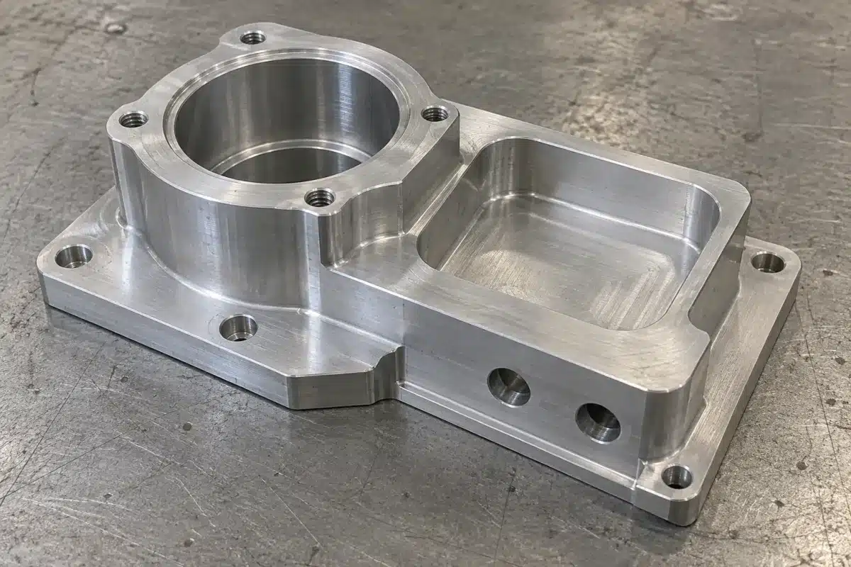
- 3-axis to 5-axis machining
- Metal & engineering plastics
- Prototype & production orders
- Checks from material to finished part
Why Choose PTSMAKE for CNC Milling?
Your parts need to fit, work and arrive ready to use. Before production, we review the features that affect assembly, machining time and inspection.
A Process That Fits Your Part
Pockets, hole patterns and features on several faces need the right setup. We plan how to hold and machine the part so key features line up.
Discutez de votre pièceDesign Review Before Production
Design for manufacturing (DFM) checks how a part can be made. We review thin walls, deep pockets and tool access, then suggest changes that keep the part working as intended.
Request a DFM ReviewChecks That Matter to Assembly
We check materials, key features during machining and the finished part. The inspection plan focuses on the dimensions that affect fit, sealing and alignment.
Discuss InspectionPrototype to Repeat Orders
Keep drawing versions, finishes and quality requirements clear as order quantities change. Tell us how many parts you need now and what you expect to order later.
Plan Your ProductionQuality Control for CNC Milled Parts
A hole can be the right size and still be in the wrong place. We match each important feature to a suitable inspection method.
Check the Features That Affect Assembly
We review reference surfaces, hole positions, pocket depths, joining faces and threads. Thin parts may move when clamps are released, so their free shape matters too. If heat treatment or a coating can change a dimension, it belongs in the inspection plan.
PTSMAKE checks incoming materials, parts during machining and finished parts. A coordinate measuring machine (CMM) can check dimensions and positions. Optical tools and surface-roughness instruments cover other agreed checks. Tell us which inspection reports you need.
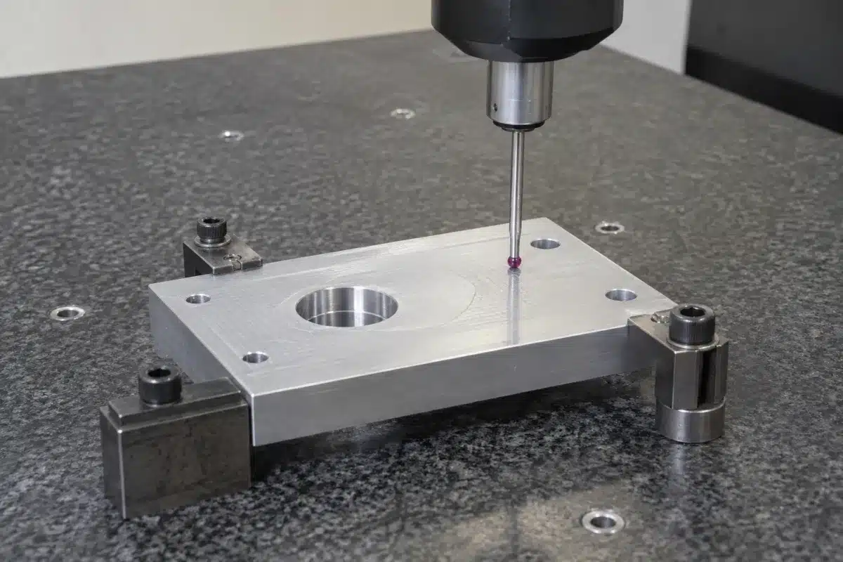
- Dessin & MatériauConfirm revision, grade and critical features.
- Réglage & Première pièceSet reference points and check the first part.
- Pendant l'usinageCheck features before the next operation.
- Acceptation finaleVerify the agreed final condition and records.
| Critical feature | What can go wrong | What to agree before production |
|---|---|---|
| Hole patterns & locating bores | Incorrect position or size prevents assembly. | Drawing reference points, size and position limits, and the measuring method. |
| Thin walls & mating faces | Clamping or cutting can bend the part. | Flatness or shape limits, how the part is supported, and checks after unclamping. |
| Threads & intersecting holes | Burrs, incomplete threads or trapped chips affect function. | Thread class/depth, gauging, deburring and cleanliness requirements. |
| Coated fits & sealing faces | Finish buildup or surface texture changes the fit. | Masking, roughness and whether dimensions apply before or after finishing. |
“ Leur expertise et leur dévouement ont assuré que nous recevions des pièces de haute qualité qui s'intégraient parfaitement dans nos systèmes. ”Sofia Bergström, Ingénieur Principal, Suède
Materials for Your CNC Milled Parts
Choose a material for the load, weight, temperature and environment your part will face. These are common options, not a complete list. Send your required grade if it is not shown.
Aluminium
- Typical parts
- Housings, plates, brackets and fixtures.
- Useful when
- Low weight, machining efficiency or heat transfer matters.
Review thin-wall rigidity, flatness and the dimensions that must be held after anodizing.
Quote Aluminum Parts →Acier inoxydable
- Typical parts
- Corrosion-exposed components and structural brackets.
- Useful when
- Corrosion resistance and mechanical performance matter.
Specify the grade and condition. Work hardening, tool access and burr removal affect cost.
Quote Stainless Parts →Acier au carbone et allié
- Typical parts
- Wear components, fixtures and loaded machine parts.
- Useful when
- Strength, hardness or a heat-treated condition is required.
Plan machining, heat treatment and finishing together where distortion can affect fit.
Quote Steel Parts →Laiton et cuivre
- Typical parts
- Electrical, thermal and fluid-handling components.
- Useful when
- Conductivity, corrosion behavior or machinability matters.
State the exact alloy. Copper and free-machining brass do not behave the same during cutting.
Discuss Copper Alloys →Titane
- Typical parts
- Weight-sensitive parts and corrosion-resistant hardware.
- Useful when
- The application justifies its strength-to-weight performance.
Review heat at the cut, tool reach and thin-wall stability before fixing the geometry.
Quote Titanium Parts →Plastiques techniques
- Options to discuss
- POM, nylon, PEEK, PC, acrylic and PTFE.
- Useful when
- Low weight, insulation, chemical resistance or sliding contact matters.
Allow for temperature, moisture and material stress when specifying tight fits.
Discuss Plastic Parts →Autres matériaux et nuances
Need a grade that is not listed? Send the material name or standard, your drawing and the part’s working conditions. We will check availability and machining options before quoting.
Surface Finishes for CNC Milled Parts
Choose the finish for the part’s use, environment and appearance. The common options below are a starting point. Coatings can change how parts fit, so define dimensions after finishing where needed.
| Finition | Typical material match | Objectif | Drawing consideration |
|---|---|---|---|
| Tel que usiné | Metals and plastics | Keep the surface left by machining, with no extra cosmetic treatment. | Define roughness only on surfaces that need it; tool marks may remain. |
| Grenaillage de billes | Suitable metal components | Create a more uniform matte appearance. | Identify cosmetic zones and areas to mask; avoid assuming every edge is unaffected. |
| Anodisation | Compatible aluminum alloys | Add a protective oxide layer and optional color. | Specify type, color, masking and the finished condition of fits. |
| Nickel chimique | Suitable metals with preparation | Add a deposited coating for the specified wear or corrosion need. | Agree coating thickness and the final dimensions of bores and threads. |
| Revêtement en poudre | Suitable metals | Add a protective and decorative coating. | Mask threads, electrical contacts and precision mating surfaces as required. |
| Black oxide / polishing | Compatible steels / selected metals | Meet the specified appearance or surface requirement. | Confirm material compatibility and required corrosion protection separately. |
A surface finish specification and a surface roughness requirement describe different things. Include both when the part needs both.
CNC Milling Production Lead Times
From urgent prototypes to production runs, plan your order around the time your parts need.
Prototypes Urgents
1 à 3 joursFor time-sensitive fit checks and product tests.
Small Batches
7 à 15 joursFor pilot builds and low-volume orders.
Tirages de la production
15 à 30 joursFor larger orders and ongoing production.
Final lead time is confirmed with your quote, based on the part, material, quantity and finish.
Six Design Choices That Can Lower Milling Costs
Review these features to simplify machining while keeping the fit, strength and function your part needs.
Allow Larger Inside Corners
Increase noncritical corner radii so a stronger cutter can reach the pocket while preserving clearance for mating parts.
Reduce Unneeded Pocket Depth
Make pockets shallower where function allows, reducing tool reach and vibration without removing required clearance or weakening the part.
Group Accessible Features
Group features on fewer accessible faces when their position is flexible, reducing repeated clamping while preserving assembly requirements.
Focus Tight Tolerances
Reserve tight tolerances for functional fits and relationships, using agreed general tolerances where extra precision adds no value.
Support Thin Walls
Add support where function allows it to reduce wall movement during clamping and cutting, while maintaining clearance and weight requirements.
Specify Useful Thread Depth
Confirm thread engagement for the load; avoid extra depth that adds tapping time without improving the joint.
Vous approuvez toute modification de dessin avant la production.
CNC Milled Part Design Examples
Design and inspection points to review for two common types of milled parts.
Machined Aluminum Enclosure
La pièce : An enclosure with a pocket, mounting holes and side openings.
Objectif de conception : Check that the tool can reach the corners. Keep enough wall thickness to hold the part without bending it.
Objectif d'inspection : Check hole positions, the flat faces that join other parts, and any dimensions that change after coating.
Discuss a Similar Enclosure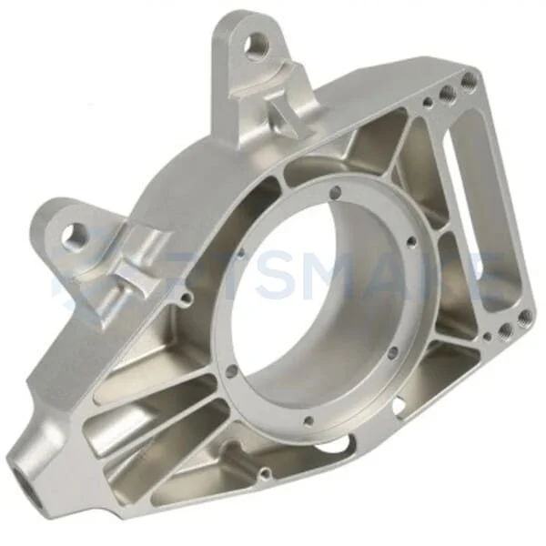
Aluminum Mounting Bracket
La pièce : An L-shaped bracket with mounting holes on two faces and a shallow pocket.
Objectif de conception : Keep enough material around the bend and holes. Check the inside corner radius and how the part will be held to machine each face.
Objectif d'inspection : Check the angle between faces, mounting-hole positions and the flatness of the base so the bracket sits correctly in the assembly.
Review Your Bracket Design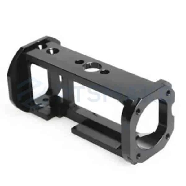
Talk to Us About Your Next CNC Milling Project
Share the part files and your production requirements. We will review the process, material, inspection needs and quotation scope with you.
Request Your CNC Milling QuoteStarting Your CNC Milling Order
Que dois-je envoyer pour un devis ?
Send your 3D model, latest drawing, material, quantity, finish and required date. Mark critical dimensions and list any inspection reports you need.
Can I order a prototype first?
Yes. Start with a prototype to check fit and function. Tell us which requirements must stay the same in later production.
Can you review an unfinished drawing?
Yes. Send the current drawing and mark any undecided details. We can discuss design changes before you approve the final production version.
What if my material or finish is not listed?
Send the grade or treatment you need and explain its purpose. We will review availability and suitability before confirming it in the quote.
Can I request inspection reports?
Tell us which dimensions, records and certificates you need. We will review the inspection scope and confirm the agreed reports in your quote.
How long does CNC milling take?
Our production lead times are 1–3 days for urgent prototypes, 7–15 days for small batches and 15–30 days for production runs. Send your drawing, quantity and finish so we can confirm the lead time for your order.
CNC Milling: Questions Buyers Ask Before Ordering
Compare suppliers, understand machining costs and prepare a clear request for quotation (RFQ). Choose a question below to jump to the answer.
1. How Do You Choose a CNC Milling Supplier?
Choose a supplier who can explain how they will make and check your part. A list of machines helps you start. You also need to know how the supplier will handle difficult features, quality checks and delivery risks. Send the current drawing. Ask what needs review before they accept the order.
A useful reply points to specific features. These might include a bearing hole, two faces that must line up, a thin wall or a coated surface. The supplier should explain any assumptions in the quote. If the model and drawing do not match, agree the correct version in writing before cutting starts. This gives you a practical way to judge the supplier’s technical understanding and communication.
- Similar work: ask for an example the supplier has permission to share. Look for similar materials, shapes and quality needs.
- Quality records: review a sample measurement report. Confirm which checks your order includes.
- Clear responsibility: ask who manages finishing, outside work and the final checks.
- Comparable quotes: use the same drawing version, quantity, documents and delivery address.
- Problem handling: agree who can approve a change and how rejected parts will be handled.
If your purchasing rules require a certificate, check that it is current and covers the right work. A quality-management certificate does not replace checks on your actual parts. For a new supplier, consider a trial order before placing a larger order. Use a part that tests the real challenges in your project. Review its measurements, packaging and delivery, as well as the communication during production.
2. How Much Does CNC Milling Cost, and What Design Changes Reduce It?
CNC milling cost depends on the work needed to deliver the finished part. The price includes material, programming, fixtures that hold the part, cutting time, finishing and inspection. A small part with a deep, narrow pocket can cost more than a larger, simple bracket. A useful price therefore needs the part design and the order requirements.
For a prototype, machine setup and programming can make up a large share of the price. For repeat batches, cutting time and part loading matter more. Ask for prices at quantities you may actually order. Ask the supplier to identify any one-time charges. Share expected future demand for planning, while making clear which quantity you are ordering now.
| Design decision | Cost question to ask |
|---|---|
| Tight tolerances on every dimension | Which features need that accuracy to work or fit? |
| Deep pockets with small corner radii | Can the pocket be shallower, wider or easier for a tool to reach? |
| Features on many faces | Can the design reduce the number of times the part must be moved and clamped? |
| Several surface finishes | Which surfaces need treatment, and which can stay as machined? |
Ask for a quote to the approved drawing and a separate option with suggested design changes. This review is called design for manufacturing (DFM). It looks for ways to make the part easier to produce while keeping its function. For example, a housing may keep its sealing face but allow larger corners inside a pocket. The supplier should mark the change and explain the saving. Your engineer then checks and approves it. Include any extra assembly or testing cost when comparing the options. Update the drawing before anyone makes the revised part.
3. What Tolerances Should You Specify on a CNC-Milled Part?
A tolerance defines how much a dimension may vary. Set it from the part’s job and the parts it must fit. Use tighter limits where variation affects assembly, sealing, movement or alignment. Agree a general tolerance for less critical dimensions. Give the supplier clear limits that can be measured, rather than describing the whole part as “high precision.”
Size is only part of the check. A hole can have the correct diameter but sit in the wrong place. A mounting face may need a flatness limit. Two bores may need a clear limit on how they line up. Use drawing datums, the reference faces, axes or points used for measurement, to explain these relationships. Follow one drawing standard. Ask the supplier to flag unclear notes before production.
- Mark the features that control fit, alignment, sealing and part replacement.
- State the units, drawing standard and general tolerances.
- Give separate limits for size, position, shape and surface roughness where needed.
- State whether the dimensions apply before or after surface treatment.
- Agree how important dimensions will be measured and recorded.
Check the full assembly too. Small size changes across several parts can add up to a large gap or an overly tight fit. Review those combined effects before tightening a single part’s drawing. State any special measurement temperature, clamping or material-conditioning requirements. Ask the supplier to confirm the limits for your actual material, shape and finish. A tolerance shown on a website may apply only to certain features. Keep the approved drawing version and inspection method for repeat orders. This helps your team and the supplier check each batch in the same way.
4. Does Your Part Need 3-Axis, 3+2 or 5-Axis Milling?
Choose the process by how the cutter can reach the features on your part. Three-axis milling suits many accessible pockets, holes and flat faces. In indexed 3+2 machining, the machine turns the part or tool to a set angle, then cuts at that angle. In simultaneous five-axis machining, the angle can change while cutting. This helps with some complex curved surfaces.
A simple plate may work well on a three-axis machine. A part with angled holes on several faces may benefit from 3+2 machining. It can reduce the need to remove and clamp the part again. A curved part may need continuous angle changes for good tool access. More axes do not, by themselves, make every part cheaper or more accurate.
| Part features | Process to discuss |
|---|---|
| Easy-to-reach features on a few faces | 3-axis milling with a suitable way to hold the part |
| Features at several fixed angles | Indexed 3+2 machining |
| Curved surfaces that need changing tool angles | Simultaneous 5-axis machining |
Ask the supplier why the proposed process suits your part. Which features need the extra axes? Will any surfaces need another setup or a separate operation? A five-axis machine may still leave work for another process. Compare the price, inspection plan and delivery date for the complete part. Focus on how the supplier will meet the drawing. If your approval process requires a specific machine or production method, state that in the quote request. Agree how any later process change will be reviewed.
5. CNC Milling vs Turning: Which Process Fits Your Part?
Milling usually suits parts with pockets, flat faces and shapes that are not mainly round. Turning usually suits shafts, sleeves and other parts built around one center axis. Many parts need both processes. Start with the main shape, then consider the smaller features. This helps the supplier choose an efficient way to make the complete part.
During turning, the part spins while a tool cuts it. During conventional milling, the cutter spins and works on a part held in place. Mill-turn machines combine these operations. They may suit a shaft with flat faces or a fitting with holes through its side. A few milled features do not mean the whole part must be made on a milling machine. The final choice also depends on size, tolerances and order quantity.
| Typical part shape | Process to discuss |
|---|---|
| Housing, bracket or manifold block | Milling for faces, pockets and hole patterns |
| Shaft, sleeve or round spacer | Turning for round surfaces and features along the axis |
| Round body with flats or side ports | Turning plus milling, or a mill-turn route |
For a part that needs both processes, mark the features that must line up. For example, a side hole may need an exact position relative to a turned surface. Agree which reference surfaces will be used and how the relationship will be checked. Ask who takes responsibility for the complete part if several suppliers are involved. Compare quotes that include the same work: all features, burr removal and final inspection. A quote for a partly turned blank leaves extra work to price. Send the complete model and drawing even when you call the job a milling project. The supplier can then review the whole part.
6. Which Material Fits Your Milled Part: Aluminum, Steel, Titanium or Plastic?
Choose the material for the conditions in which the part will work. Consider load, temperature, corrosion, weight and electrical needs. Then compare the cost and difficulty of machining it. Give the supplier an exact grade and material condition. “Aluminum” or “plastic” alone leaves too much open for a reliable quote.
Aluminum often suits lightweight housings and brackets. Different steel grades offer different levels of strength, wear resistance and corrosion resistance. Titanium may be worth considering when strength, weight or corrosion needs justify its cost. Engineering plastics can offer low weight, electrical insulation or good sliding properties. They also need careful review when a part must hold its size in use.
| Material family | Confirm before quoting |
|---|---|
| Aluminium | Grade, temper or treatment condition, appearance and anodizing needs |
| Steel or stainless steel | Grade, hardness, corrosion conditions and heat treatment |
| Titane | Grade, required certificates and the properties the part needs |
| Plastique technique | Exact grade, added fillers, moisture exposure and working temperature |
Plastic parts can change size after machining because of moisture, heat or stress within the material. A size measured just after production may change in a warm or damp assembly. Agree any needed conditioning, such as holding the part at a set temperature and humidity before measurement. If other materials are allowed, list them and ask for separate prices. Have your engineer approve any change. Check its effect on fit, finish and product testing. Compare the full cost of a finished part that meets the requirements. A low raw-material price alone does not show which option will cost less to make and use.
7. How Should You Design Thin Walls, Deep Pockets and Internal Corners?
Keep the part stiff enough to machine, and give the cutter room to reach each feature. Thin walls can bend under cutting or clamping forces. Deep pockets may need long tools that bend more easily. Small inside corners may need small cutters. A part with all three features can need slower cutting, special fixtures or a design change.
One minimum wall thickness or maximum pocket depth will not suit every part. A short rib supported at both ends behaves differently from a tall, free-standing wall. Mark the surfaces that must stay as designed. Then show which areas can change. Ask the supplier to review the actual shape, material, tool reach and support in your model.
- Thin walls: add support, increase thickness or reduce height where the design allows.
- Deep pockets: check whether all the depth is needed and whether the tool can reach more easily.
- Inside corners: allow suitable radii. Discuss a small clearance cut if a square part must fit inside.
- Nearby holes: check how much material remains between the hole and the wall.
- Inspection : state whether a flexible part is checked without clamps or held in a defined position.
Consider an electronics housing with a close-fitting cover. The sealing face may need to stay unchanged, while the pocket can have larger inside corners. That is a useful design-for-manufacturing change to discuss. A clearance cut in a corner that carries a load needs closer review because it may reduce strength. Ask the supplier to mark each proposed change on the model or drawing. Your engineer should check the effect and approve a new version. Keep the required strength, fit and sealing while making the part easier to produce.
8. How Do Surface Finishes Affect Dimensions and Part Performance?
Include the finish in the part design and quote request. A treatment can change fit, corrosion resistance, wear, electrical contact or appearance. It can also add work and inspection time. State the actual requirements. A description such as “black finish” or “smooth surface” is too broad for a part with critical fits or a controlled appearance.
Identify what each surface needs to do. A sealing face may need a set roughness. An electrical contact area may need masking to keep it free of coating. A visible housing may need a set texture and color range. Anodizing forms an oxide layer. Plating and coating add material in other ways. Allow for these effects in the machining sizes and final checks.
- State the process, standard, type and required thickness where needed.
- Mark areas to mask, important fits, threads, contact faces and allowed rack-contact marks.
- State which dimensions apply after treatment and how to check them.
- Mark visible surfaces. Use an approved sample to agree appearance when needed.
- Check that the quote includes required finish records and checks after treatment.
A bearing seat needs the correct fit after finishing. An outside face may mainly need appearance and protection. Give each area its own clear instructions. Agree any masking or size allowance before machining starts. Also plan the packaging. Parts with the correct finish can still arrive scratched if they rub together in transit. State how finished surfaces and thin edges should be protected. Compare quotes for the same final condition. If another company applies the finish, agree who checks the result and who handles a problem. This keeps responsibility clear across the full order.
9. What Should a CNC Milling Quote Request and Inspection Plan Include?
A request for quote (RFQ) gives suppliers the details they need to price the same finished part. It should also define how your team will accept the delivery. Send the current 3D model and a version-controlled drawing for details such as tolerances and finish. Include the quantity and delivery needs. Agree which file takes priority if documents disagree, and fix any mismatch before ordering.
Choose inspection records to suit the part’s risks. A material certificate gives information about the material supplied. A certificate of conformance states that the order meets the agreed requirements. A dimensional report records measured sizes and other features within its agreed scope. Ask for the records you need when requesting a quote. Also agree which features and how many parts will be checked.
| RFQ information | What it tells the supplier |
|---|---|
| Part number, version and matching files | Exactly which part to quote |
| Material, finish, quantity and required date | What the order must include and when it is needed |
| Critical features and acceptance limits | What must be checked before shipment |
| Report format, sample size and batch records | Which records must arrive with the parts |
| Packaging and delivery address | How to protect and deliver the order |
For a new part, decide whether you need first-article approval: a review of initial parts before the rest proceed. Agree who approves them and how quickly. If you need proof that the process can hold tolerances across a batch, agree the study and data needed. One good sample cannot show that on its own. Compare incoming quotes in a simple table. Include excluded work, inspection records and any exceptions to the drawing. Get unclear items confirmed in writing so that you compare the same finished order.
10. What Determines Prototype and Production Lead Time?
PTSMAKE offers production lead times of 1–3 days for urgent CNC milling prototypes, 7–15 days for small batches and 15–30 days for production runs. The final lead time is confirmed with your quote. The part design, material, quantity and finish determine which schedule is realistic for your order.
A prototype may need new programming and a fixture before cutting can start. A repeat order may use an existing process. It still needs machine time, material and the correct drawing version. Finishing, special records and approval of the first parts can also affect the date. Tell the supplier when you actually need the parts. Explain whether they are for a fit check, product test or production assembly.
- Send matching, approved files and answer technical questions before production starts.
- Check stock of the required material grade and the availability of its certificates.
- Include finishing, inspection and approval time in the schedule.
- Discuss whether delivery in stages would help and which parts are needed first.
- Allow time for transport, customs where relevant and handling at the destination.
For an urgent order, ask which step controls the delivery date. Faster approval, an approved material already in stock or delivery in stages may help. Check that each option still meets the needs of the test or product. For regular orders, share realistic demand estimates. Agree how drawing changes will be handled, whether fixtures will be kept and how repeat batches will be accepted. Confirm the delivery date in the quote for your specific order. Website turnaround times may cover only certain parts or finishes. Use the agreed order schedule when planning your project and update it if the requirements change.
Get Your Custom CNC Milling Quote
Send your model, drawing, material and quantities. Tell us the features that matter to your assembly and when you need the parts.