
CNC Drejeservice til Brugerdefinerede Præcisionsdele
Komplekse CNC-drejede dele fremstillet efter dine tegninger, herunder præcisionsspindelaksler, hydrauliske ventilspoler, hule rotoraksler og præcisionskonnektorhuse. Dimensionelle tolerancer så stramme som ±0.005 mm på egnede funktioner, underlagt tegning og materialegennemgang.
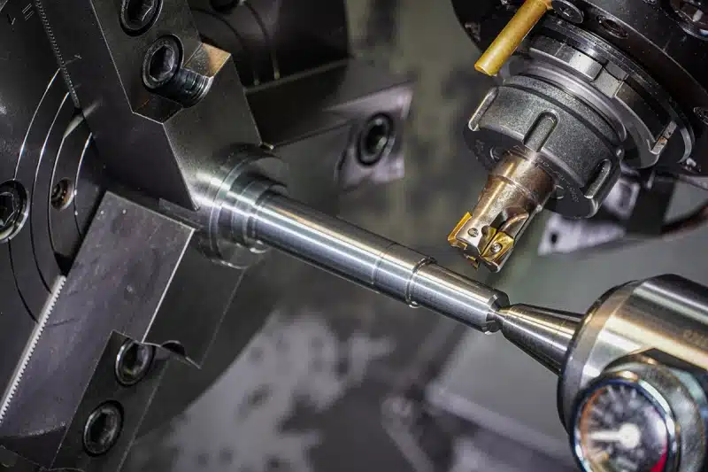
- Komplekse drejede geometrier
- Metaller & ingeniørplast
- Prototype & gentagen produktion
- Tegningsstyrede præcisionskontroller
Hvorfor vælge PTSMAKE til CNC-drejning?
Flere lejesæder, dybe boringer, smalle riller og gevindgrænseflader kræver en koordineret bearbejdnings- og inspektionsplan.
En rute der passer til geometrien
Start med den drejede profil, gennemgå derefter tværhuller, flader og andre funktioner. Aftal eventuel yderligere fræsning eller efterbehandling som en del af det komplette tilbud på delen.
Diskuter din delNyttig designfeedback
Gennemgå dybe indvendige trin, tynde husvægge, slanke aksler og rilleadgang. Vi foreslår praktiske ændringer til din godkendelse, samtidig med at delens pasform og funktion beskyttes.
Anmod om en designgennemgangKontroller for funktionelle pasninger
Størrelse alene beviser ikke justering. Definer lejesæder, tætningsflader, referenceakse og gevindkrav, så inspektionsplanen matcher din tegning.
Gennemgå kritiske funktionerEt klart grundlag for gentagne ordrer
Hold tegningsrevision, materialetilstand og acceptkriterier konsekvente. Del din prøvemængde og forventede partier, så begge stadier kan gennemgås.
Planlæg din ordrePræcision for komplekse drejede dele
PTSMAKE kan opnå dimensionelle tolerancer så stramme som ±0.005 mm på egnede funktioner. Tegningen, materialet, geometrien og den endelige bearbejdning bestemmer, hvor denne kapacitet gælder.
Forbind hvert krav med en kontrol
For en spindelaksel, definer lejejournaler og referenceakse. For en ventilspole, identificer præcisionslandinger, rillepositioner og overfladefinish. Rundhed, udløb og overfladeruhed er separate krav, ikke underforstået af en ±0.005 mm størrelsestolerance.
PTSMAKE's CNC-kvalitetsproces dækker indgående materiale, in-process kontroller og slutinspektion. Aftal målemetoder, prøveudtagning og registreringer under tilbudsgivning, herunder kontroller efter afspænding, varmebehandling eller belægning.
- Tegning og materialeRevision, legering, tilstand og kritiske funktioner.
- Opsætning og første delArbejdsfastholdelse, referenceflader og første kontroller.
- Kontroller undervejsFunktioner påvirket af værktøjsslid eller den næste operation.
- Endelig acceptFærdig tilstand, aftalte registreringer og beskyttelse.
| Funktionel funktion | Risiko for samlingen | Aftal på tegningen eller inspektionsplanen |
|---|---|---|
| Lejejournaler & lokaliseringsboringer | En korrekt diameter med dårlig form eller justering kan stadig fejle. | Pasningsgrænser, referencedata og eventuelle krav til rundhed eller udløb. |
| Skuldre & tætningsflader | Fladefejl eller uegnet tekstur påvirker sæde og tætning. | Aksial placering, fladerelation, kanttilstand og specificeret ruhed. |
| Gevind & tværhuller | Ufuldstændige gevind eller krydsende grater hindrer samling. | Gevindstandard/klasse, brugbar længde, måling og tilgængelig afgratning. |
| Tynde husvægge & belagte pasninger | Frigivet spændingsstress eller belægningsopbygning ændrer dimensioner. | Målestøtte, endelig overfladetilstand og eventuelle maskerede områder. |
“Deres ekspertise og dedikation sikrede, at vi modtog dele af høj kvalitet, der problemfrit integrerede sig i vores systemer.”Sofia Bergström, Ledende Ingeniør, Sverige
Materialer til komplekse CNC-drejede dele
En spindelaksel, hydraulisk ventilspole og tyndvægget konnektorhus står over for forskellige belastninger, slid og krav til dimensionel stabilitet.
Aluminium
- Præcisionskonnektorhuse
- Vælg legeringen for lav vægt, vægstivhed og den ønskede finish.
Trinborede huller, tynde vægge og tætningsriller kræver stabil fastspænding. Angiv de færdige gevind- og boregrænser efter anodisering, og identificer elektriske kontaktområder, der skal forblive ubelagte.
Gennemgå et aluminiumshus →Rustfrit stål
- Ventilstempler og gevindforbindelseshuse
- Tilpas kvaliteten til korrosionseksponering, slid og materialetilstand.
Identificer præcisionsglideland, tætningskanter og interne passager. Valg af kvalitet skal afbalancere den krævede hårdhed og korrosionsbestandighed med bearbejdning; nem skæring alene er ikke nok.
Diskuter en rustfri komponent →Kulstof- og legeret stål
- Præcisionsspindelaksler og rotoraksler
- Angiv styrke, hårdhed og den leverede materialetilstand.
Marker lejejournaler, skuldre og hule sektioner, der styrer samlingen. Gennemgå varmebehandling og eventuel afsluttende præcisionsbearbejdning sammen, så de kritiske dimensioner gælder for den færdige del.
Gennemgå en præcisionsaksel →Messing, bronze og kobber
- Konnektorhuse, kontakter og ventilkomponenter
- Elektriske, væskekontakt- og glideopgaver kræver forskellige legeringer.
For trinvise kontakter og gevindhuse, definer ledningsevne, kontaktflader og eventuel belægning. For bronze glidekomponenter, angiv også det modstående materiale, belastning og smøring.
Vælg en legering til din del →Titanium
- Hule aksler og præcisionsgevindhuse
- Brug en specificeret kvalitet, hvor dens styrke-til-vægt- og korrosionsegenskaber er nødvendige.
Dybe boringer og slanke sektioner kombinerer begrænset stivhed med krævende skæreforhold. Inkluder den uunderstøttede længde, minimumsvæg og kritiske grænseflader i bearbejdningsgennemgangen.
Gennemgå en titaniumdel →Teknisk plast
- Trinvise konnektorisolatorer og ventilsæder
- Vælg kvaliteten for temperatur, fugt og kemisk eksponering.
For POM-, nylon- eller PEEK-komponenter, gennemgå vægtykkelse, spændingsaflastning og størrelsesændringer i drift. Definer konditionerings- og målekravene for tætsiddende boringer og tætningsprofiler.
Diskuter en præcisionsplastdel →Andre materialer og kvaliteter
Send materialespecifikationen og arbejdsforholdene. Vi vil gennemgå tilgængelighed og bearbejdelighed med din tegning.
Overfladefinisher til drejede dele
Vælg finishen for hver arbejdsflade. Spindeljournaler, ventilstempelkanter og konnektorhusoverflader har forskellige funktionelle krav.
| Hvor på delen? | Finish til diskussion | Drejespecifikt krav |
|---|---|---|
| Spindeljournaler og ventilstempelkanter | Som drejet eller specificeret præcisionsfinish | Definer den endelige diameter, pasform og ruhed. Identificer eventuelle overflader, der skal forblive ubelagte; udseende alene beviser ikke pasformen. |
| Roterende tætningskontaktbånd | Finish specificeret for tætningen | Følg tætningsproducentens krav til overfladetekstur, herunder grænser for spiralformede bearbejdningsmærker. Beskyt dette bånd mod kosmetisk sandblæsning. |
| Aluminiumskonnektorhuse | Anodisering | Angiv den færdige boring og udvendige diameter. Aftal hvilke pasflader, gevind og elektriske kontakter der skal maskeres. |
| Slid- eller korrosionsudsatte metaloverflader | Strømløst nikkel | Belægning opbygges på ydre og indre overflader. Angiv tykkelse og inspicer kritiske diametre og gevind i belagt tilstand. |
| Ikke-tætnende stålakseloverflader | Sort oxid, hvor det er kompatibelt | Angiv eventuel olie eller anden efterbehandling. Behandl ikke sort oxid som en erstatning for hærdning eller et defineret krav til korrosionsydelse. |
| Synlige konnektorhusoverflader | Perleblæsning | Marker det kosmetiske område. Beskyt tætningsflader, lejesæder og gevind, hvor sandblæsning ville stride mod deres specificerede overfladetilstand. |
Varmebehandling ændrer materialets egenskaber; den gennemgås separat fra disse overfladefinisher. Inkluder den, når du specificerer materialet og leveringsplanen.
CNC Drejetider & Levering
Fra presserende prototyper til produktionsserier, del din ordremængde og ønskede dato, så vi kan bekræfte tidsplanen for dine dele.
Presserende Prototyper
1–3 dageTil tidskritiske pasformskontroller og designvalidering. Send din tegning og deadline til gennemgang.
Små-Batch Ordrer
7–15 dageTil pilotbygninger og indledende montagekørsler, før der flyttes til større mængder.
Produktionsserier
15–30 dageTil større produktionsordrer og planlagte gentagne serier. Del mængden og leveringsplanen.
Endelig leveringstid afhænger af tegningen, materialetilgængelighed, efterbehandling og inspektionskrav. Bekræft startdato, afsendelsesdato og transporttid i tilbuddet.
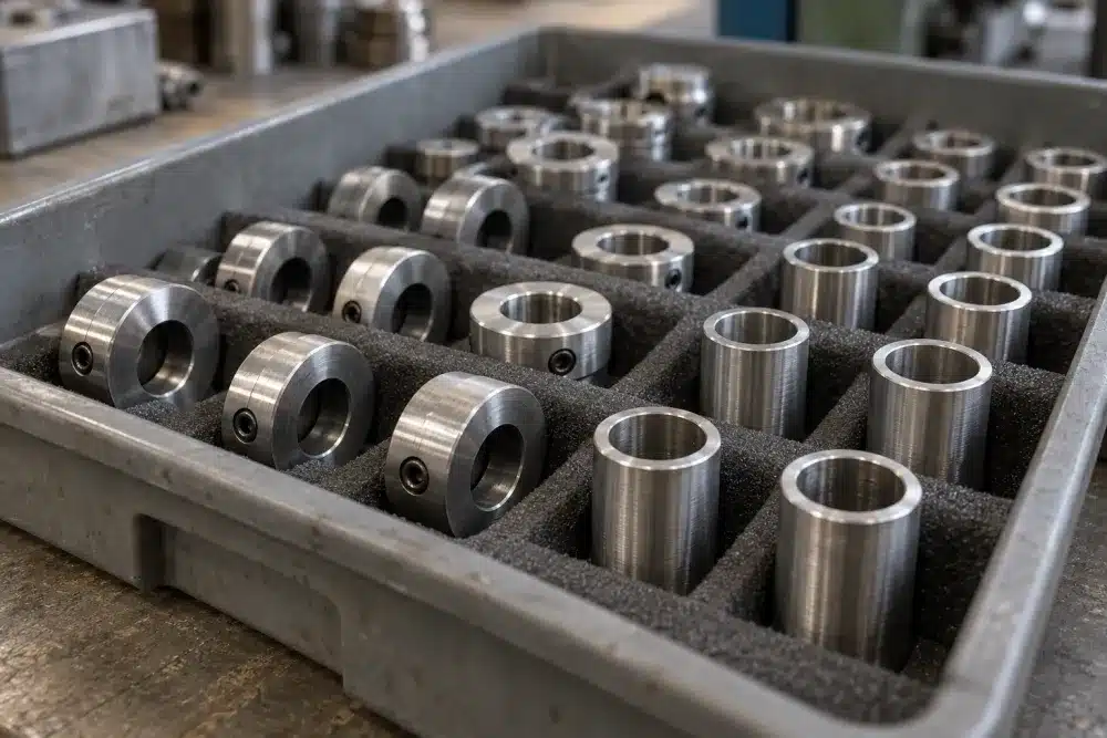
Få et Tilbud på Dine Specialdrejede Dele
Send tegningens revision, materiale, mængde og finish. Fremhæv de pasninger, gevind og inspektionsrapporter, der er vigtige for din montage.
Send Tegninger for et TilbudSeks Designvalg Der Kan Sænke Drejeomkostningerne
Brug den geometri din del kræver, med tilstrækkelig adgang og støtte til at bearbejde den konsekvent.
Efterlad et Praktisk Holdeområde
Diskuter en brugbar gribelængde eller offermaterialetillæg, så delen kan holdes uden at mærke kritiske overflader.
Begræns Unødvendig Bore Dybde
Reducer blindhulsdybden hvor funktionen tillader det; længere værktøjsudhæng øger udfordringen med at kontrollere vibrationer og huldiameterkvalitet.
Oprethold Tilstrækkelig Vægstivhed
Øg vægtykkelsen hvor montagen tillader det, hvilket reducerer deformation fra fastspænding og skæring uden at ofre nødvendig frigang.
Skab Plads til Gevindudløb
Gennemgå en standard aflastnings- eller udløbsplads, hvor pasningsfrigang, styrke og tætningskrav tillader det.
Fokuser Præcision Hvor Det Virker
Anvend stramme krav til størrelse, geometri og ruhed på funktionelle overflader; brug aftalte generelle krav til ikke-kritiske funktioner.
Forenkle Sekundære Funktioner
Juster tværhuller eller flader, når deres orientering er fleksibel, hvilket hjælper med at forenkle indeksering eller sekundære opsætninger, samtidig med at montageadgangen bevares.
Du godkender eventuelle tegningændringer før produktion.
Eksempler på Komplekse Drejede Dele Designs
To repræsentative deltyper viser, hvordan præcisionsoverflader, interne funktioner og inspektionskrav arbejder sammen.
Hydraulic Valve Spool
Delen: A multi-land spool with annular grooves and closely spaced shoulders.
Designfokus: Define the working diameters, groove positions and edge requirements against the mating valve bore. Review material condition and finishing before setting the machining route.
Inspektionsfokus: Agree how to check land diameters, roundness, surface finish and shoulder positions from the drawing datums.
Discuss a Valve Spool Design
Precision Connector Housing
Delen: A turned housing combining stepped internal seats, a thin-wall section, an external thread and a seal groove.
Designfokus: Define the mating insert, wall thickness, thread engagement and seal location. Review tool access and support for the internal and external features.
Inspektionsfokus: Check internal seat diameters and depths, thread fit and the bore-to-outside relationship. Include coating allowance and burr control in the finished-part requirements.
Review a Connector Housing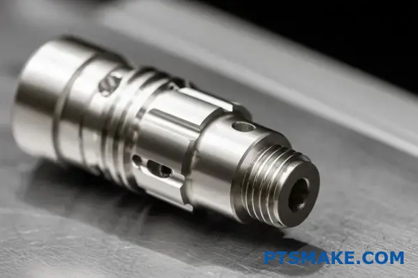
Starting Your CNC Turning Order
A few details help us review your request and prepare a useful quotation.
Hvad skal jeg sende for et tilbud?
Send a 3D model if available and a dimensioned drawing with revision, material, finish and critical requirements. Include quantities, the delivery destination, target date and required inspection documents.
What CNC turning tolerances can you achieve?
PTSMAKE can achieve dimensional tolerances as tight as ±0.005 mm on suitable features. We confirm feasibility from the drawing, material, geometry and final processing. Specify roundness, runout and surface finish separately; the size tolerance does not guarantee those requirements.
Can you review a prototype and later production batches?
Yes. Include the prototype quantity and expected batch sizes in the request. The quote can then address setup, inspection and repeat-order requirements for the stages you need.
What if my part also needs flats, slots or cross-holes?
Include every feature in the same request. We will review the complete machining route and identify additional operations in the quotation. The drawing determines whether turning alone is sufficient.
Can you work from a 2D drawing only?
Send the drawing for review. We will check whether it defines the part fully or whether a model or additional dimensions are needed before quoting.
How do I request material or inspection records?
List each required document and the features it must cover when requesting the quote. Documentation, sampling and traceability requirements should be agreed before production.
Will you change my drawing to reduce cost?
Any proposed change is for your approval. Keep your functional requirements clear so an alternative radius, groove, tolerance or setup feature can be evaluated against the part’s job.
A Buyer’s Guide to CNC Turning
Work through the decisions that affect how your turned part fits, performs and costs—from the drawing and machining route to final inspection and repeat orders.
1. Is CNC Turning the Right Process for Your Part?
CNC turning is a strong starting point when the main features share a common axis: outside diameters, bores, shoulders, tapers and circumferential grooves. The workpiece rotates while a cutting tool removes material. Representative parts include precision spindle shafts, hydraulic valve spools, hollow rotor shafts and precision connector housings. The right choice still depends on the complete part, including features that cannot be made by basic turning.
A side hole, wrench flat or keyway introduces a different tool direction. Live tooling uses powered cutters on a turning machine to make some of these features. A turn-mill route may reduce transfers between machines, but feasibility depends on tool access, feature position, workholding and the equipment available for the order. Send the complete model to PTSMAKE for a route review; the presence of one round feature does not establish how the whole part will be made.
| Main geometry | Rute at diskutere |
|---|---|
| Coaxial diameters, bores and shoulders | Turning with an agreed sequence for both ends |
| Round body with side holes or flats | Live-tool turning or turning followed by milling |
| Mostly flat faces and pockets | Milling, with turning only where useful |
Ask which features can share a setup and how alignment will be maintained when the part is reclamped. Fewer setups can help, but do not prove the finished tolerances. Compare the proposed route against the drawing, inspection plan and total quoted cost. Keep any design changes as a separate option for engineering approval.
For parts that combine several processes, explore our CNC machining capabilities. Our CNC lathe machining guide provides additional process background.
2. What Should Your CNC Turning RFQ and Drawing Define?
A useful request for quote defines both the shape to manufacture and the conditions for accepting it. Send matching 3D and 2D files with a part number and revision. The model communicates geometry; the drawing records requirements such as tolerances, threads, surface texture and inspection notes. Agree which document controls if information differs, and resolve conflicts before releasing the order.
PTSMAKE can achieve dimensional tolerances as tight as ±0,005 mm on suitable features. We confirm feasibility against your drawing, material, geometry and final process requirements. Mark the dimensions that need this precision; roundness, runout and other geometric controls must be specified and reviewed separately.
For a turned part, make the functional axis, locating faces and fit diameters clear. Show a section view where an internal step, groove or blind bore would otherwise be ambiguous. Distinguish full thread length from hole depth, and identify the surfaces that must remain free of coating or clamping marks. State whether acceptance dimensions apply before or after finishing.
- Product definition: current files, units, material grade and condition, drawing standard and general tolerances.
- Functional requirements: critical dimensions, datum references, threads, surface texture, edge condition and finish.
- Ordreomfang: quantity to order now, possible repeat quantities, required date and delivery destination.
- Accept: inspection scope, required records, packaging and any first-article approval.
If a dimension is still being developed, label it for discussion instead of mixing a trial value into a released drawing. Request the baseline quote and any cost-saving alternative separately. A short change table—feature, proposed revision, reason and approval—helps prevent a DFM suggestion from becoming an unintended manufacturing instruction. Save the accepted quotation with its drawing revision so a future order has a clear starting point.
3. How Do You Control Datums and Runout on a Turned Part?
A correct diameter does not by itself show that a surface runs true to the axis used in the assembly. Define the functional references on the drawing, then specify the geometric controls needed for the part’s job. A datum is an exact reference established from the identified physical feature or features. On a shaft, that reference may be an axis established from its bearing seats.
Runout describes surface variation as a part rotates about a specified datum axis. Circular runout checks individual circular sections; total runout controls the entire specified surface during rotation and measurement along that surface. Neither term should be used as a casual replacement for a size tolerance. Roundness, alignment and surface size answer different questions. KEYENCE’s runout overview illustrates the distinction.
For example, imagine a precision spindle shaft with two bearing seats and a sealing diameter. Its acceptance plan must establish the drawing’s datum axis before checking the seal surface. Simply gripping an unrelated rough diameter could produce a result that does not represent the assembly. This is an illustrative inspection problem, not a prescription for a particular datum scheme.
Discuss where the part will be held during machining, which surfaces are finished together and how the inspection setup reproduces the required references. If the part must be turned around, ask how the second operation locates from the first. Record the controlled surface, datum reference and acceptance limit explicitly. Avoid a general note such as “all diameters concentric” when the function requires a specific, measurable relationship.
4. How Should Shaft and Bore Fits Be Specified?
Choose the fit from how the mating parts must behave, then put measurable limits on the drawing. A sliding joint needs controlled clearance. A press-fit joint needs controlled interference. A bearing seat also depends on the bearing design, load, temperature and which ring rotates relative to the load. There is no single shaft tolerance that suits every turned assembly.
Use the mating component manufacturer’s guidance where available, and include the bearing or bushing specification with your drawing. A fit designation needs its nominal size and governing standard; explicit upper and lower limits can also make the required result clear. Check the full tolerance range of both mating parts, including any coating.
| Grænseflade | Define before ordering |
|---|---|
| Bearing seat | Bearing specification, fit limits, surface texture and geometric controls |
| Hydraulic valve spool and mating bore | Required clearance across both tolerance ranges and operating conditions |
| Press-fit pin or sleeve | Interference range, mating material, wall stiffness and assembly method |
Do not tighten every diameter to match one critical seat. Mark the functional zones so the machining and inspection effort goes to the features that need it. Specify shoulder geometry and adjacent corner clearance too: a correctly sized bearing seat can still fail to locate the bearing if the shoulder transition interferes. Send the relevant mating information when requesting a fit review.
5. What Makes Threads, Grooves and Shoulders Easier to Machine?
Give each feature enough tool access and a clear functional specification. Standard thread forms and practical groove proportions usually offer more tooling choices than custom profiles. Any change must preserve the joint, seal or locating function. Do not enlarge a seal groove or remove a shoulder simply because it is easier to cut.
For threads, state the thread standard, size, pitch, class, hand and required full thread length. Identify blind-hole depth separately. The tool needs room to enter and leave the cut, and internal threading also needs space for chips to escape. A thread running directly into a shoulder deserves a specific relief and tool-clearance review. The relief should follow the applicable design requirement, rather than a universal rule copied onto every drawing.
For grooves, specify width, depth or root diameter, position and any required corner radii. Narrow, deep grooves can limit tool stiffness and chip evacuation. If a groove accepts a seal or retaining ring, use that component’s design guidance and identify the mating part. An internal groove behind a small opening needs review of the tool’s complete path, not just whether its tip fits inside.
At shoulders, clarify whether a mating part must sit flush. A permissible corner radius, a relief or clearance on the mating component may solve the interface, but these are design choices. Call out burr-sensitive edges, particularly at cross-hole intersections and thread starts. Ask PTSMAKE to flag difficult access and proposed changes on the drawing before approving production; tooling convenience alone is not a reason to change a functional feature.
6. What Changes for Long Shafts, Thin Walls and Deep Bores?
These features need a review of stiffness, support and the order of operations. A long, slender shaft can deflect under cutting loads. A thin-walled connector housing or sleeve can change shape under clamping pressure. A hollow rotor shaft may combine a deep bore with several critical outside diameters. The bore requires a tool that reaches the feature while remaining stable. Overall part size alone does not capture these risks.
For shafts, show the smallest working diameter and unsupported lengths as well as total length. Discuss whether end support or another support method is appropriate, and whether any center holes or contact areas are permitted. For sleeves, define the required condition for measurement. A part that is round while clamped may behave differently after release; the acceptance method must match the drawing and intended use.
Deep bores introduce a separate problem: the boring bar itself can bend or vibrate. Shorter reach and greater tool stiffness generally improve stability, while the bore geometry limits the available tool. Sandvik Coromant’s guide to slender tooling explains this relationship. Its tool-specific limits are not universal limits for your part.
Possible changes include a shorter unsupported section, more wall thickness, easier access from the opposite end or a less demanding nonfunctional surface. The appropriate option depends on the complete design. If geometry cannot change, ask how the supplier proposes to hold, machine and verify it. Review roundness, straightness, runout and surface texture wherever those affect function; agreeing only a diameter tolerance may leave the main risk unresolved.
7. How Do You Choose a Material for Turned Parts?
Start with the part’s operating conditions, then compare suitable grades for machinability, supply and total cost. The material must satisfy the required strength, wear, corrosion, temperature and weight needs. “Aluminum,” “stainless steel” or “plastic” is not a complete purchase specification. State the exact grade and its required condition, including heat treatment where relevant.
For metal parts, discuss the finished condition before choosing the manufacturing sequence. Hardness requirements, subsequent heat treatment and surface finishing may influence when critical diameters are completed and checked. If an alternative grade could reduce cost or procurement time, request it as a separate option. Similar names or broadly similar strength do not establish equivalence for every application.
A bronze sliding bushing illustrates why the function matters: load, speed, lubrication and the mating shaft help determine the suitable bearing material. That is a different selection problem from a brass threaded body or a copper electrical contact. Our comparison of brass, bronze and copper gives additional material background; the alloy still needs to meet your part’s specification.
Engineering plastics need their own dimensional review. Moisture absorption, temperature and residual stress can affect the final size. Material stiffness also affects how a part can be supported and clamped. A tolerance that works for a metal bushing should not automatically be copied to a polymer replacement without considering its use and measurement conditions. For POM parts, our POM machining guide expands on material selection, clamping and dimensional checks.
Send the relevant service environment and mating-material information with the drawing. Explain whether electrical insulation, chemical exposure or repeated motion drives the choice. If material documentation is required, identify the document and traceability needed when requesting the quote. Ask for confirmation of the specified grade’s availability for your order. A list of commonly machined materials is a starting point for discussion, not confirmation that every size and condition is stocked.
8. How Do Surface Finishes Affect Dimensions and Fit?
Specify the finish together with the final dimensional requirements. A part that fits before coating may not fit afterward. External build-up can increase an outside diameter and reduce an opening, while preparation steps can also change the surface. The machining allowance must match the actual finish process and its variation.
Anodizing converts aluminum at the surface into an oxide layer. Part of that layer penetrates the original surface and part builds above it, so coating thickness is not the same as outward dimensional growth. The Aluminum Anodizers Council referenceguide explains this distinction. Confirm the intended coating, thickness range and allowance with the finishing provider instead of applying one growth factor to every process.
- Identify bearing seats, sealing surfaces, threads and other fit-critical features.
- State the finish specification, thickness where required, color and acceptable appearance.
- Mark masked areas and permissible rack or contact locations.
- Confirm whether dimensions are checked before finishing, after finishing or at both stages.
Keep surface texture separate from cosmetic appearance. A visually bright shaft is not proof that it meets a specified roughness limit. On a sealing or bearing surface, define the texture requirement and measurement area that matter to the function. Likewise, a matte finish is not a substitute for controlled dimensions. Agree who verifies the final condition if machining and finishing are handled in separate steps, and include protection of finished surfaces in the packaging requirements.
A rotary seal contact band may also need limits on machining lead—the fine spiral pattern left on a shaft that can move fluid along the seal interface. Use the seal manufacturer’s requirements, rather than assuming a lower roughness value alone solves leakage. For stainless parts requiring passivation, see our stainless steel passivation guide; specify the required treatment and acceptance checks with the drawing.
9. Which Inspection Checks and Records Do You Need?
Choose inspection from the features that determine acceptance. Outside diameter, bore size, thread fit, runout and surface texture may need different methods. Ask how the critical features will be checked and what records the quote includes. A list of instruments does not tell you which checks will be carried out on your order.
Use a numbered drawing or agreed feature list to connect each reported result to its requirement. Specify the drawing revision, measurement condition and sample scope. For runout, include the datum setup; for finished fit diameters, identify the required stage of inspection. If a special gauge or assembly test is needed, agree its design, availability and acceptance rule before production.
| Record | What to agree |
|---|---|
| Dimensional report | Features, measured results, limits, sample size and part identification |
| Material documentation | Required material data and connection to the supplied batch |
| Certificate of conformance | Order requirements and the scope of the conformity statement |
| First-article review | Inspection scope, approval owner and whether further work awaits approval |
A first-article result describes the part or sample inspected; it does not establish long-term process capability by itself. If your program requires capability data, agree a suitable sampling study and measurement approach. NIST’s process capability guidance explains why stability and adequate data matter. Keep special documentation requirements in the RFQ so their cost and timing are included from the start.
10. How Do You Compare Quotes and Move from Prototype to Production?
Compare quotes for the same delivered, accepted part. Match the drawing revision, quantity, material condition, finish, inspection scope and delivery destination. Check exclusions and one-time charges as well as unit price. A lower machining price can be misleading if a required finish, report or secondary operation is priced elsewhere or omitted.
Turning cost includes material, setup, tooling, machining time and the work needed after cutting. Large changes in diameter can increase stock removal. Deep internal features, additional setups and demanding final checks may add work even on a small part. Ask which features drive your quote and request any proposed design alternative separately. Review its effect on assembly and performance before approving a revised drawing.
For prototypes, state what the parts must prove: fit, motion, finish or performance in the intended environment. Before increasing quantity, decide which requirements and process details must carry over. Record accepted changes, critical inspection results and any open issues from the trial order. A successful fit check is useful evidence, but may not test wear, temperature behavior or repeated production.
Build the schedule around the whole route: technical approval, material, setup, machining, finishing, inspection and shipping. Confirm when lead time starts and whether the quoted date means ready to ship or delivered. For repeat orders, agree revision control, fixture retention where relevant and how batches will be identified. Share realistic demand estimates, while distinguishing forecasts from quantities actually ordered. This gives PTSMAKE the information needed to propose a route, inspection scope and schedule for your specific project.
Ready to Quote a Complex Turned Part?
Share the latest drawing, material, quantities and required date. Highlight critical dimensions, deep bores, thin walls and threaded interfaces so PTSMAKE can review the complete machining and inspection plan.