
Aluminum CNC Machining Services
PTSMAKE provides aluminum CNC machining services (3/4/5-axis milling, turning, mill-turn, wire EDM) for US and European buyers, from prototype to production.
Custom aluminum parts manufactured in China to your drawings and specifications. Choose from eight aluminum grades, with surface finishing coordinated for your project.
- ISO 9001:2015Certified quality management
- 20+ yearsManufacturing experience
- 100,000+ partsParts delivered
- 98% on-timeDelivery record
Why Aluminum for Precision Parts
Aluminum combines low weight with strength and thermal conductivity. The right grade depends on the loads, operating environment and finish your part needs.
Capabilities
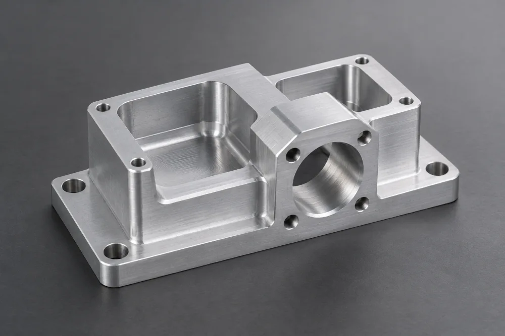
3/4/5-Axis CNC Milling
For pockets, contours and features on multiple faces. Additional axes provide access to angled and hard-to-reach features.
Discuss Your Milled PartCNC Turning
For round components with diameters, shoulders, bores and grooves, including shafts, bushings and spacers.
Discuss Your Turned PartMill-Turn Machining
For parts that combine round features with flats, pockets or off-center holes.
Discuss Your Mill-Turn PartWire EDM
For through-profiles and narrow slots where a continuous wire path can pass through the part.
Review Your ProfileExplore our CNC machining services, 5-axis CNC machining and Swiss machining service for more on process selection.
Quality & Inspection
ISO 9001:2015 certified quality management for custom parts, from prototype to production.
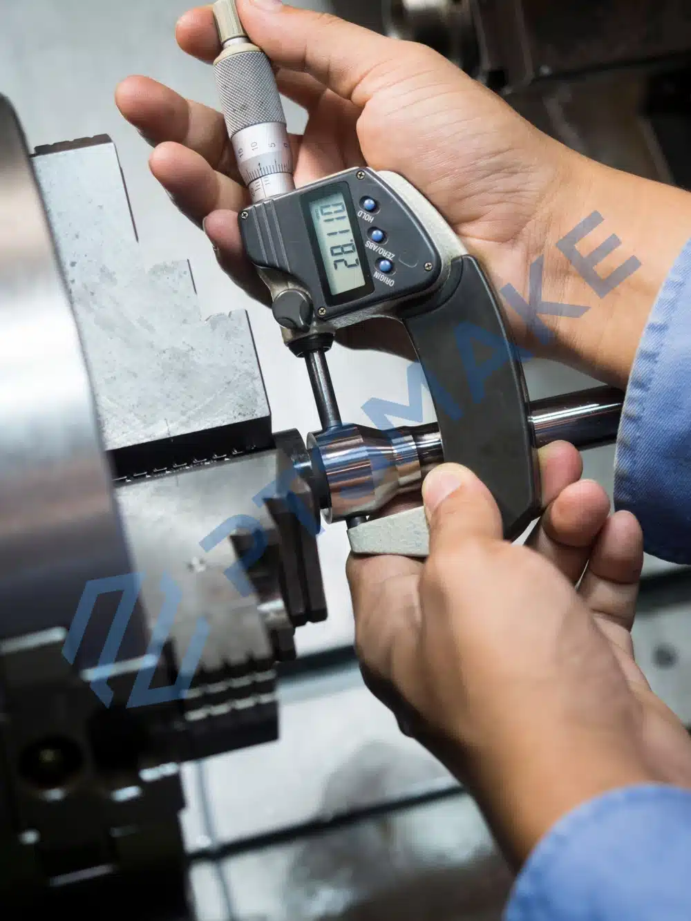
Precision starting from ±0.005 mm
Feasibility is evaluated from your drawing. The achievable precision depends on the alloy, geometry, feature size and surface finish.
A bore that fits, a mounting face that seats correctly and a finished surface that meets your specification each need clear acceptance criteria.
- Fit and alignment: identify mating dimensions and reference surfaces.
- After finishing: state which dimensions apply to the finished part.
- Documentation: include any required inspection or material records in your inquiry.
Alloys We Machine
Compare eight grades we machine. Specify the temper as well as the alloy: it affects strength, machining behavior and the finished result.
Aluminum 6061
A versatile choice for brackets, housings and general machine parts, with a useful balance of strength and corrosion resistance.
Quote Your 6061 Part →Aluminum 7075
For highly loaded parts where strength is a priority. Consider corrosion protection and the required finish when selecting the temper.
Quote Your 7075 Part →Aluminum 2024
A high-strength alloy with good machinability for loaded fittings and structural components. Surface protection is an important part of the specification.
Quote Your 2024 Part →Aluminum 5052
Consider 5052 for corrosion-resistant covers and mounting plates. Check the specified temper against the loads your part must carry.
Quote Your 5052 Part →Aluminum 5083
For corrosion-resistant plates and industrial components. Specify the material condition when strength and dimensional stability are critical.
Quote Your 5083 Part →Aluminum 6082
A structural alloy for brackets and machine components. Often specified when the design calls for a combination of strength and corrosion resistance.
Quote Your 6082 Part →Aluminum 6063
For heat sinks and electronics components where thermal performance and anodized appearance matter. Check strength against the part’s loads.
Quote Your 6063 Part →MIC-6
Cast tooling plate for fixtures and base plates. Its stress-relieved condition supports dimensional stability during machining.
Quote Your MIC-6 Part →Surface Finishes
PTSMAKE coordinates these finishes through external partners. Consider both the desired appearance and the effect on mating surfaces.
Swipe to see all columns →
| Finish | Typical Uses | Define With Your Drawing |
|---|---|---|
| Anodizing Clear / black / hard | Appearance and surface protection; hard anodizing for wear-focused requirements. | Alloy, appearance reference, coating specification, masked areas and final dimensions. |
| Powder coating | An opaque finish where color, texture and coverage matter. | Color, gloss, texture and protection of mating surfaces from coating buildup. |
| Bead blasting | A matte texture on specified surfaces. | Visible faces, target texture and any subsequent anodizing or coating. |
| Polishing | A smoother, brighter surface appearance. | Surfaces to polish, desired gloss and the edges or details that must be preserved. |
Compare our surface finishing services. Appearance and finished dimensions need review for the chosen alloy and process combination.
Aluminum CNC Machining Production Lead Times
Production lead times for planning your order. Your quote will confirm the schedule for your part.
Urgent Prototypes
1–3 daysFor urgent prototype requests, subject to feasibility and scheduling.
Small Batches
7–15 daysFor small production batches with defined material and finish requirements.
Production Runs
15–30 daysFor production quantities, including planned repeat orders.
Final lead time depends on the part, material, quantity, finish and inspection requirements.
Design Choices That Can Lower Aluminum Machining Costs
Allow sufficient cutter access while preserving the fit, strength and appearance your part needs.
Open Up Internal Corners
Larger internal radii can allow a stiffer cutter where the assembly permits; check the radius together with pocket depth and component clearance.
Keep Pockets Only as Deep as Needed
Reducing nonessential depth can shorten tool reach and improve access; preserve space for components, fasteners, and connections.
Support Thin Walls
Extra wall thickness or local ribs can improve rigidity; keep the required internal clearance, mounting access and weight target.
Define Functional and Visible Surfaces
Specify the fit of a locating bore and the finish of a visible face separately. Use appropriate general requirements for the remaining surfaces.
Proposed design changes require your approval before production.
Industries Served
Custom aluminum components for weight-sensitive assemblies, thermal management and mechanical systems.
From Structural Features to Visible Surfaces
A robotics bracket needs the right balance of weight, strength and mounting accuracy. A machine fixture needs stable support and reliable locating surfaces.
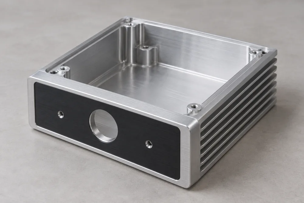
An amplifier housing adds another set of priorities: component clearance, heat transfer, connector locations and the appearance of exposed faces.
- Aerospace
- Automotive
- Medical devices
- Robotics
- Precision electronics
- Industrial machinery
Starting Your Aluminum Machining Order
Answers to common questions about cost, precision and aluminum selection.
How Much Does It Cost to Machine Aluminum?
The cost depends on the alloy, part size, geometry, quantity, tolerances and finish. Deep pockets, difficult tool access and extra setups can increase machining time. A quote needs your drawing and order requirements; part weight alone is not enough to estimate the work involved accurately.
Can Aluminum Be Machined to Tight Tolerances?
Yes. Precision starting from ±0.005 mm is subject to drawing review. Alloy, geometry, feature size and finishing all affect feasibility. Identify the dimensions that control fit or alignment, and state whether they apply before or after finishing, so each requirement can be assessed for your part.
What Aluminum Grade Is Easiest to Machine?
MIC-6 offers excellent machinability for tooling plates and fixtures, and 2024 also machines well. Ease of machining is only one selection factor. The best grade for your part also depends on strength, corrosion resistance, stock form, surface finish and how the component will be used.
A Buyer’s Guide to Aluminum CNC Machining
Practical guidance on alloy selection, part specifications and comparing machining quotes.
1. How Do You Choose the Right Aluminum Alloy?
Start with the load, operating environment, thermal requirements and finish. A highly loaded bracket, a visible electronics housing and a fixture plate need different material properties. Choose the alloy and temper together: the grade name alone does not specify strength.
6061 is a practical starting point for many general components. Consider 2024 or 7075 when strength is a major design driver, while checking corrosion protection and finishing requirements. MIC-6 is cast tooling plate used where stability during machining matters. For electronics and amplifier parts, the thermal path and mating surfaces deserve as much attention as the alloy’s strength.
General reference, part-specific verification required. Values below refer only to the stated temper and stock form. “Typical” values describe representative material; “minimum” values are published limits for the stated product. They are not interchangeable design allowables or a guarantee for your part.
Swipe to see all columns →
| Alloy | Yield Strength (MPa) | Machinability | Typical Uses |
|---|---|---|---|
| 2024 T351 rod/bar | 324 typical | Good in the stated temper. | Loaded fittings and aerospace components. |
| 5052 H32 rolled stock, 0.4–6.3 mm | 160 minimum | H32 is more difficult to machine than harder tempers. | Covers, mounting plates, and industrial components. |
| 5083 H111 rolled stock | 125 minimum proof stress; verify thickness-specific requirements | Challenging in the rolled condition. | Industrial machinery and automotive components. |
| 6082 T6/T6511 extruded stock, 5–150 mm section | 260 minimum | Good; chip control remains important. | Structural brackets and machine components. |
| 6061 T6/T651 rod/bar | 276 typical | More demanding than alloys developed for easy machining. | Robotics brackets, housings, and machinery parts. |
| 6063 T6 extruded stock, section up to 3.2 mm | 170 minimum | Less suited to heavy machining than 6061. | Heat sinks and precision electronics components. |
| 7075 T6/T651 rod/bar | 503 typical | Fair in T6/T651. | Highly loaded mechanical and aerospace components. |
| MIC-6 Stress-relieved cast tooling plate | 105 typical | Excellent for plate-based parts. | Fixtures, base plates, and machine tooling. |
The stock dimensions above identify the reference data; they do not define PTSMAKE’s stock availability or machining limits. Specify the required alloy, temper, product form, and material specification. Machinability also depends on the tools, cutting conditions and part geometry; the descriptions are general guidance, not a common rating scale.
Use the aluminum machinability guide to explore the selection tradeoffs, and the 5083 aluminum machining guide for considerations specific to that grade.
2. Which Machining Process Fits Your Aluminum Part?
The shape of the part determines how it can be machined. Pockets and mounting faces often suit milling; concentric diameters suit turning. When a part combines these features, consider how each operation will locate from the surfaces produced in the previous step.
Swipe to see all columns →
| Process | Features to Evaluate | Key Review Point |
|---|---|---|
| 3/4/5-axis CNC milling | Pockets, mounting faces, contours, and features on several sides | Tool reach, approach angle, and access around the part |
| CNC turning | Diameters, shoulders, bores, and grooves | Rotational geometry, part support, and relationships between diameters |
| Mill-turn machining | Turned diameters combined with flats, pockets, or off-center features | How the milled features locate relative to the turned surfaces |
| Wire EDM | Through-profiles and narrow slots | A continuous wire path through the material and suitable entry access |
Angled faces and features on several sides may benefit from 5-axis CNC machining when the additional movement improves tool access or reduces setups.
For small turned components with slender geometry, see our Swiss machining service. Our CNC machining services page covers broader process selection for custom parts.
3. How Should You Specify Critical Dimensions?
A size requirement and a positional requirement solve different problems. A bore can have the correct diameter but still fail to align with the shaft in an assembly. Your drawing needs to define both the feature size and its location relative to the surfaces that position the part.
Use datums to identify those reference surfaces or axes. For a bracket, the mounting face may establish how the part sits, while a locating hole establishes its position. Include an assembly view when the relationship is difficult to explain in a single part drawing.
- Fits: identify the surfaces that locate, slide, clamp, or support another component.
- Feature relationships: define which faces or axes establish the part’s position in the assembly.
- Finished condition: state which dimensions apply after the specified surface treatment.
- Acceptance records: list any measurements or material documents needed so their scope can be confirmed.
For thin walls or heavily pocketed parts, include the complete geometry. Clamping and material removal can influence the released part, so a single detail view may not provide enough information to assess feasibility. Where several components must fit together, supply the relevant mating dimensions or assembly view.
Apply appropriate general requirements to the remaining features. Reserve tighter controls for dimensions that affect function, and identify any requirements that must be checked after finishing.
4. How Do Finishes Affect Fit and Appearance?
Specify the finished condition of the part, especially where components fit together. A bore sized before treatment may not have the same clearance afterward. Identify the dimensions that apply after finishing and any areas that must remain untreated.
Anodizing develops an oxide layer at the aluminum surface. Powder coating adds a coating over it. Both require attention at mating interfaces: identify bores, threads, locating faces, and contact areas whose final dimensions or surface condition matter. Show which surfaces need treatment and where masking is required, then confirm the complete specification against the part.
Bead blasting creates a matte texture; polishing develops a smoother, brighter appearance. Neither description fully defines the acceptance standard. Identify visible faces, the intended texture or gloss, and any appearance reference. If preparation is followed by anodizing, assess the combined finish rather than treating the two appearances as independent results.
- Appearance: specify color, texture, visible surfaces, and any parts that must be viewed together.
- Function: mark mating, electrical-contact, and thermal-contact areas requiring a particular surface condition.
- Protection: identify masking boundaries and locations where handling or contact marks would affect acceptance.
A color name alone cannot define an exact match between different alloys or finishes. Where appearance is critical, include a representative reference and agree on how the finished part will be accepted. See our surface finishing services and aluminum anodizing guide when preparing these requirements.
5. What Drives Aluminum Machining Cost?
Finished part weight is a poor guide to machining cost. A lightweight housing may start as a much larger block and require extensive material removal. A heavier, simpler part can take less machining time. Compare quotes against the same drawing revision, quantity and acceptance requirements.
- Starting stock and material removal: stock size, alloy and the amount removed all affect the work required.
- Setups and access: features on several sides may need repositioning or more complex machining. Hard-to-reach features can slow an otherwise simple part.
- Order quantity: programming and setup costs are spread across the batch. Request separate quantity options when comparing prototypes with a planned production order.
- Finishing and acceptance: include masking, appearance references and required inspection records in every quote request so you can compare the same scope.
Ask which requirements have the greatest effect on the quote. If a feature can change, explain its function and the space available in the assembly. Any proposed saving should be evaluated against fit, strength and appearance before you approve a drawing change.
6. What Should You Send for a Quote and Lead Time?
Send a matching drawing and model with the same revision identifier. Include the alloy and temper, quantity, finish and required date. If you need several quantity options, list them separately so the quote can distinguish prototype costs from production pricing.
- Drawing and model: identify the current revision, critical features and any assembly details needed to understand the fit.
- Material and finish: state the specification, treated surfaces and any appearance reference.
- Order requirements: include quantities, your required date and the inspection or material records you need.
- Open choices: distinguish requirements that are fixed from alternatives you are willing to consider.
The production lead time overview provides planning guidance. Your quote will confirm the schedule for the specified part, quantity and finish.
For a repeat order or a move from prototype to production, flag changes from the previously evaluated part. Reference the approved drawing revision rather than relying on “same as before.”
Get Your Aluminum CNC Machining Quote
Send your drawing and specifications for a quote on your next prototype or production order.
Related Guides & Resources
- 7075 vs. 6061 aluminum: strength and application tradeoffs
Compare material priorities before specifying aluminum for a mechanically loaded part.
- Which aluminum is easiest to CNC machine?
Explore how alloy selection affects machinability and the choice of material for your design.
- Key considerations for 5083 aluminum machining
Review machining considerations when preparing a component specified in 5083.
- A practical guide to anodizing aluminum alloys
Understand the anodizing process before defining appearance and functional requirements.
- Black anodized aluminum: finish selection and practical considerations
Consider the material and appearance details behind a black anodized surface.
- Aluminum heat-sink materials and grades
Compare material considerations for thermal management in electronics and amplifiers.
- Aluminum CNC machining: a practical service guide
Read the supporting guide for broader context when preparing your machining inquiry.