Are your AI server GPUs hitting thermal walls faster than your cooling hardware can keep up? With H100s pushing 1000W and B200s climbing higher, off-the-shelf heat sinks just don’t cut it anymore. One leak, one warped cold plate, and your entire rack goes down.
CNC machining is the manufacturing method that produces the precision cold plates, manifolds, and quick-disconnect fittings AI servers need for reliable liquid cooling. It delivers the tight tolerances (±0.01mm), micro-channel features, and leak-free sealing surfaces that direct-to-chip cooling demands.
In this guide, I’ll walk you through every CNC-machined part inside an AI server cooling loop. From cold plate channel design to leak testing, material picks, and cost drivers, you’ll get the practical details to spec parts that work the first time.
Why AI Servers Demand a New Class of Cooling Hardware
The latest generation of AI processors is pushing thermal limits beyond what traditional methods can handle. We’re now dealing with GPUs that generate immense heat, making effective cooling a primary design challenge. Standard, off-the-shelf solutions simply can no longer maintain safe operating temperatures.
The Soaring Thermal Challenge
Modern GPUs, such as NVIDIA’s GB200, produce heat loads exceeding 1000W per chip. This intense power density overwhelms conventional air-cooling systems. As a result, hyperscale data centers are rapidly transitioning to more robust liquid cooling systems to manage this thermal reality effectively.
| GPU Model | Thermal Design Power (TDP) |
|---|---|
| NVIDIA H100 | 700W |
| NVIDIA B200 | 1000W |
| AMD MI300X | 750W |
| NVIDIA GB200 NVL72 | ~120kW/rack |
Why Traditional Cooling Fails
Standard heat sinks are designed for lower thermal loads. They lack the surface area and material properties to dissipate over 1000W from such a small footprint. This inadequacy risks thermal throttling, performance degradation, and ultimately, hardware failure in advanced AI servers.
The shift to liquid cooling systems is not just a trend; it’s a necessity for high-performance AI. However, this transition introduces new manufacturing complexities. The components involved, such as cold plates and manifolds, demand a level of precision that traditional manufacturing cannot deliver consistently.
The Role of Precision Manufacturing
Effective AI GPU thermal management relies on components with intricate internal channels and extremely tight tolerances. These features are essential for maximizing the coolant’s surface contact and ensuring leak-proof operation under high pressure. This is where advanced manufacturing becomes critical for success.
Material and Geometric Complexity
Liquid cooling hardware often uses materials like copper for its excellent thermal conductivity. The challenge lies in creating complex internal geometries that promote Turbulent Flow1, which significantly enhances heat transfer compared to smooth, laminar flow. Achieving these designs requires sub-millimeter precision.
| Cooling Method | Heat Dissipation Capacity | Manufacturing Complexity |
|---|---|---|
| Air Cooling | Low-Medium | Low |
| Liquid Cooling | High | High |
At PTSMAKE, we’ve found that CNC machining is the only method that provides the necessary control to produce these components reliably. It allows us to create custom-designed cold plates and distribution manifolds that meet the exact specifications required for cooling next-generation AI accelerators.
The extreme heat of modern AI servers makes advanced liquid cooling systems essential. Standard solutions are inadequate, making precision CNC machining the critical manufacturing partner for creating effective thermal management hardware that performs reliably under demanding conditions.
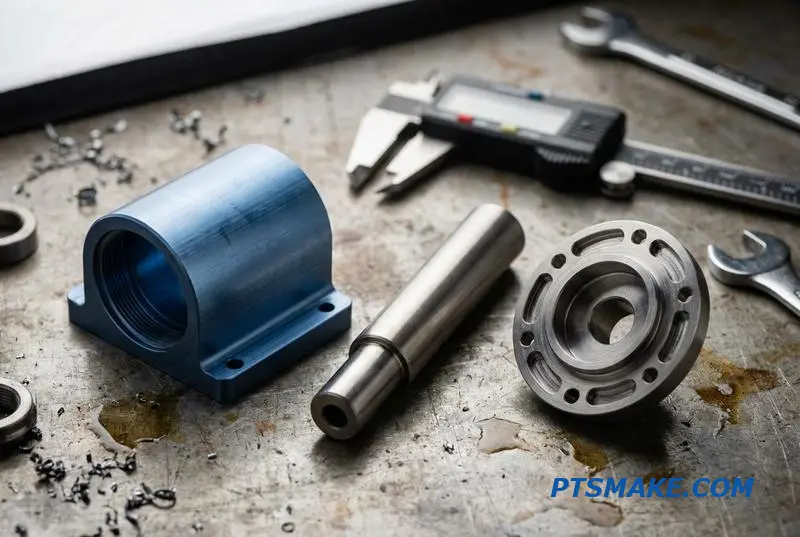
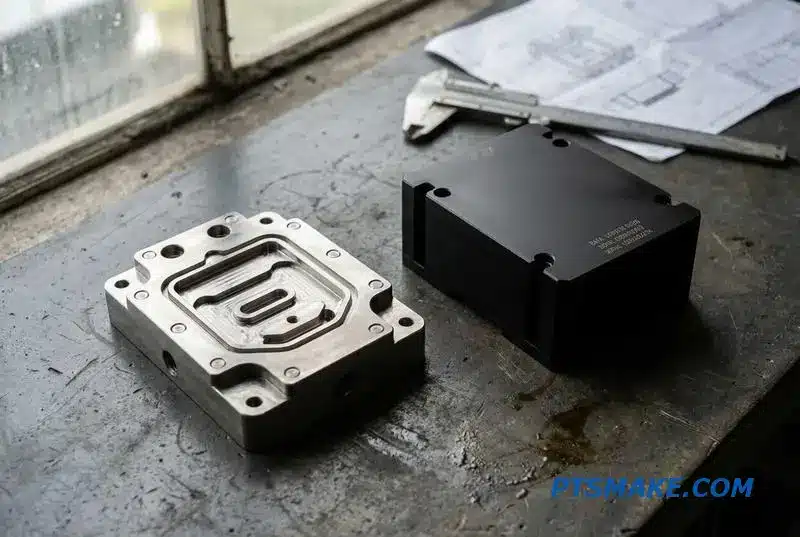
Anatomy of a Liquid-Cooled AI Server: Where CNC Parts Fit
The incredible power of AI servers comes with a massive heat problem. Direct-to-chip liquid cooling is no longer a luxury but a necessity. I see these systems as intricate networks where every component’s precision is critical for performance and reliability. It’s not just about plumbing.
The Component Map
Think of a liquid cooling loop as a city’s water system. Coolant must travel from a central distribution unit (CDU) to each heat source (GPU/CPU) and back again without a single drop lost. CNC machining creates the high-precision infrastructure for this journey.
Key Machined Parts
Here is a breakdown of the essential CNC parts in a typical loop. Each one requires a specific approach to manufacturing to ensure the entire system functions flawlessly under intense thermal loads.
| Component | Function | Why CNC Machining is Critical |
|---|---|---|
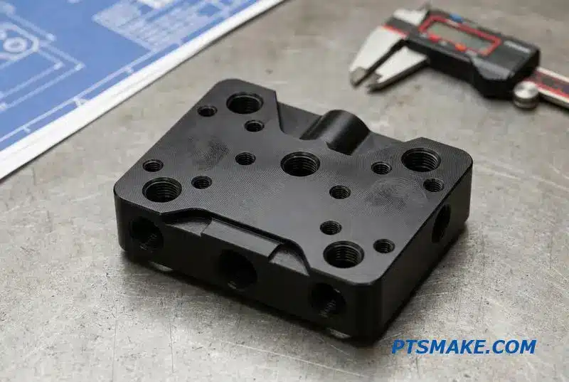
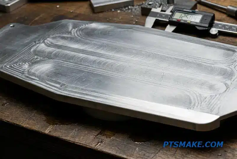
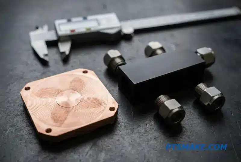
| Cold Plates | Transfer heat from GPU/CPU to coolant | Perfect flatness for thermal contact |
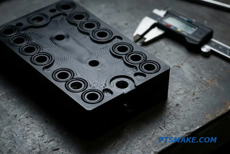
| Manifolds | Distribute coolant to multiple cold plates | Complex internal channels, leak-proof ports |
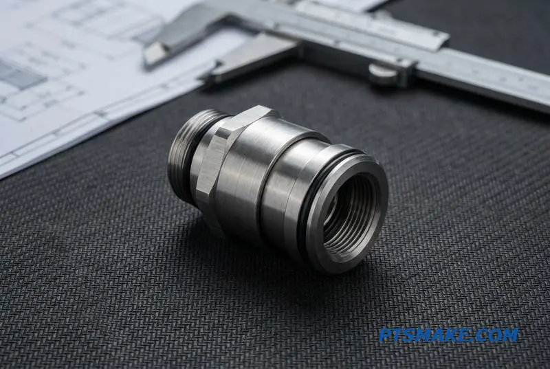
| Couplings | Allow for hot-swapping server blades | Tight tolerances for secure, zero-drip seals |
| Fittings & Connectors | Connect tubing to components | Precise threads and sealing surfaces |
Precision at Every Point
The demand for perfection in liquid cooling systems is absolute. A microscopic leak or a poorly-seated cold plate can lead to catastrophic hardware failure. This is where the value of precision CNC machining becomes clear, moving beyond simple part creation to enabling system-wide reliability.
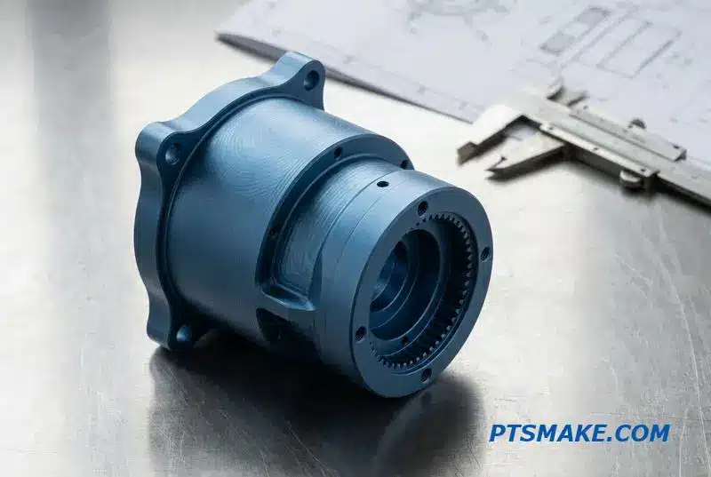
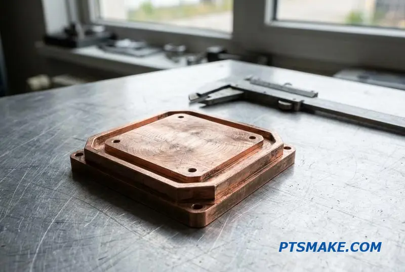
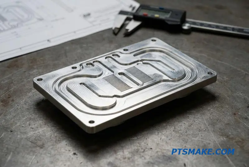
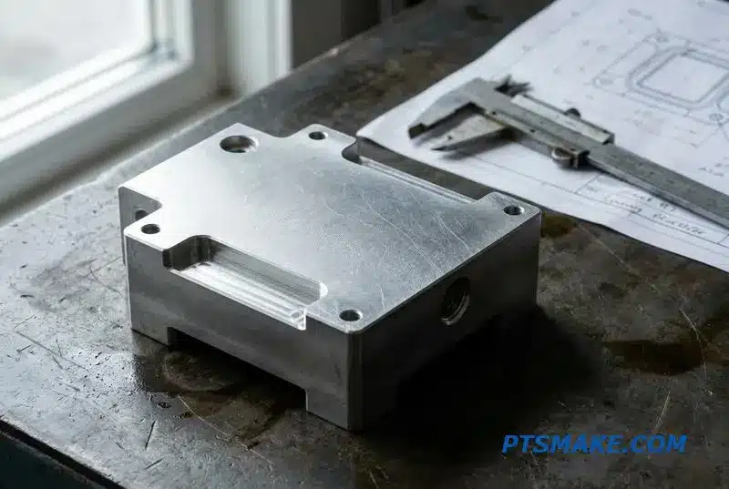
Cold Plates: The Heart of Heat Transfer
The cold plate is the most critical component. It sits directly on the processor. We often machine these from copper for its excellent thermal conductivity. The internal micro-channels, which maximize surface area for heat exchange, demand incredibly precise milling to ensure optimal coolant flow and pressure.
Manifolds and Couplings: The Flow Controllers
Coolant distribution manifolds are the system’s central nervous system. They direct flow efficiently and must be perfectly sealed. The same goes for quick-disconnect couplings. At PTSMAKE, we focus on achieving flawless surface finishes and dimensional accuracy to guarantee leak-proof connections, even after hundreds of cycles.
Material Integrity and Thermal Stress
When a cold plate uses a copper base and an aluminum top, their different expansion rates under heat can cause stress. Understanding the Coefficient of Thermal Expansion2 is crucial. Proper design and machining prevent material fatigue and potential leaks over the server’s lifespan.
| Part Feature | Machining Requirement | Impact of Failure |
|---|---|---|
| Cold Plate Flatness | Tolerance < 0.01mm | Poor thermal transfer, CPU overheating |
| Manifold Port Sealing | Surface Finish Ra < 0.8μm | Coolant leakage, system short-circuit |
| Coupling O-ring Groove | Dimensional Accuracy ±0.02mm | Seal failure, connection drip |
In AI server liquid cooling systems, precision isn’t just a goal; it’s a fundamental requirement. CNC machining ensures every component, from the cold plate to the smallest fitting, meets the extreme tolerances necessary for reliable, leak-proof operation in high-stakes computing environments.
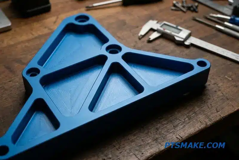
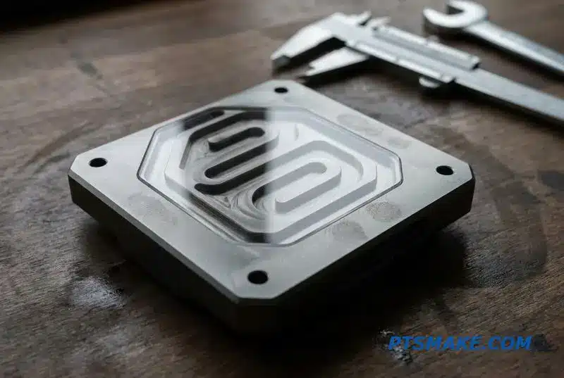
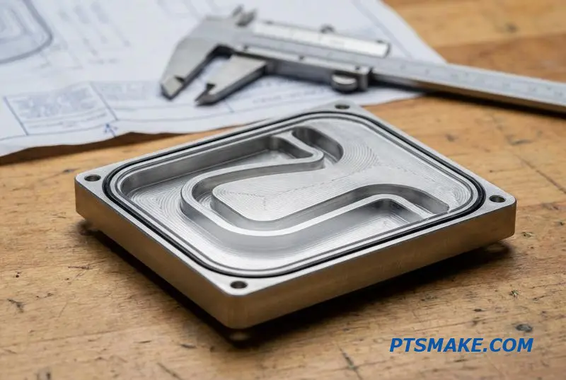
Cold Plates: The Thermal Interface That Makes or Breaks Performance
A cold plate is the heart of any high-performance liquid cooling system. It is the critical component transferring heat from a source, like a CPU, to the coolant. Its design and manufacturing precision directly dictate the system’s overall efficiency. A poorly made plate can cripple performance entirely.
Common Cold Plate Designs
There are several core designs, each with specific applications. The choice depends on thermal load, pressure drop requirements, and cost. Serpentine channels are simple, while microchannels offer maximum surface area for extreme heat flux.
| Design Type | Best For | Key Characteristic |
|---|---|---|
| Serpentine Channel | Low to moderate heat loads | Simple, low-cost machining |
| Drilled Plate | High pressure applications | High structural integrity |
| Microchannel | High heat flux density | Maximized surface area |
| Brazed Fin | Complex thermal needs | High thermal performance |
Material Selection and Precision
Choosing the right material is a balance of thermal performance and system compatibility. While C1100 copper offers superior thermal conductivity, 6061 aluminum is lighter and more cost-effective. Chrome copper (C18150) provides a middle ground with good conductivity and better strength.
However, mixing metals like copper and aluminum in a loop without proper inhibitors can cause Galvanic Corrosion3, which degrades the system over time. At PTSMAKE, we guide clients through these trade-offs to ensure long-term reliability for their liquid cooling systems.
| Material | Thermal Conductivity (W/mK) | Key Benefit |
|---|---|---|
| 6061 Aluminum | ~167 | Lightweight, cost-effective |
| C1100 Copper | ~385 | Excellent thermal transfer |
| C18150 Chrome Copper | ~320 | High strength, good conductivity |
The Importance of Tight Tolerances
Precision is non-negotiable for a CNC machined cold plate. We typically hold general tolerances to ±0.05mm. The critical sealing surfaces, however, are machined to ±0.01mm to prevent leaks. The contact face requires a surface finish of Ra 0.8µm or better for optimal thermal transfer.
A high-performance cold plate hinges on three factors: the right design, the correct material choice for thermal and chemical compatibility, and exacting CNC machining precision. Neglecting any of these elements will compromise the entire liquid cooling system’s effectiveness and reliability.
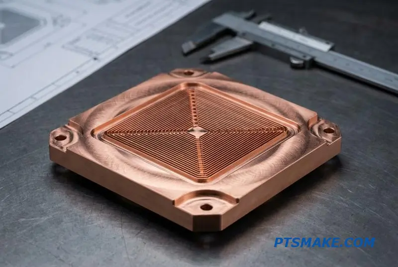
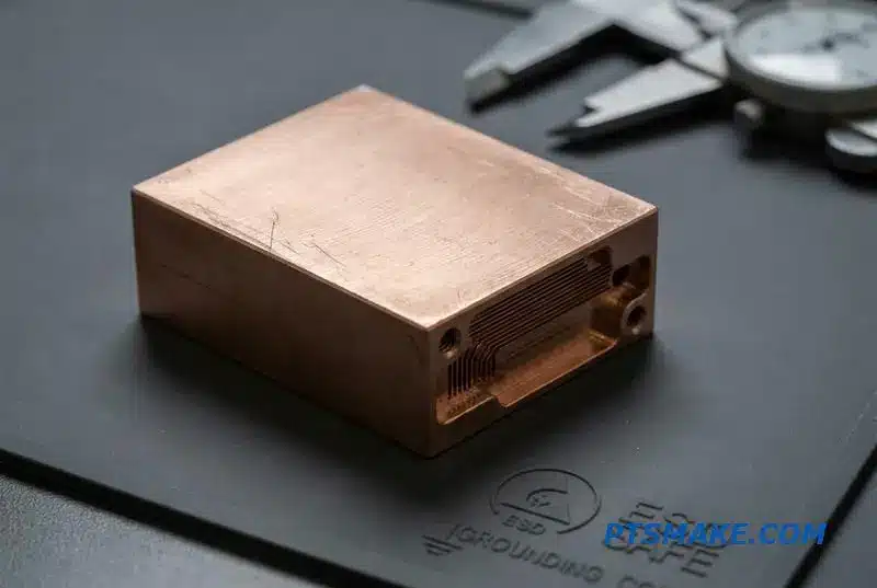
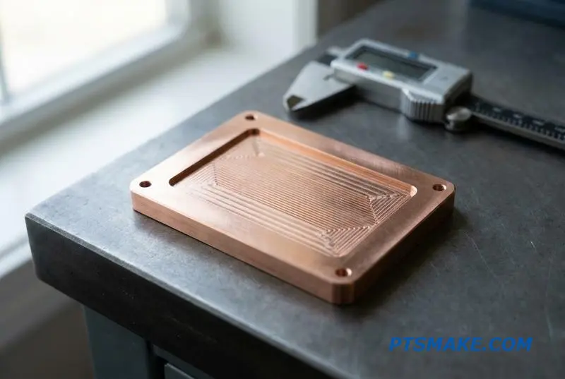
Microchannel Cold Plate Machining: When Standard Channels Are Not Enough
As AI chips become more powerful, they generate immense heat. Standard liquid cooling systems are hitting their limits. This is where microchannel cold plates come in. They offer a much larger surface area for heat transfer, which is critical for these high-performance applications.
The Rise of Microchannels
Traditional channels are simply not efficient enough anymore. To cool modern electronics effectively, we need to machine incredibly small and deep channels. This allows for superior performance in compact liquid cooling systems, keeping sensitive components within their ideal operating temperatures.
Key Machining Hurdles
Machining these features is not simple. We often deal with fin gaps between 0.3mm and 0.8mm. The real test is achieving high aspect ratios—the ratio of fin height to its width—often ranging from 8:1 to 15:1.
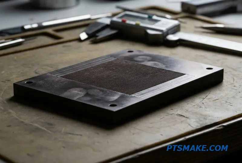
The demand for custom microchannel cold plates is driven by the intense Heat Flux4 of new AI processors. Successfully machining these parts requires specialized tooling and a very stable setup. We rely on micro end mills, high-speed spindles, and extremely rigid CNC machines to prevent tool breakage and maintain accuracy.
Comparing Manufacturing Methods
While CNC machining is a primary method, other options exist. Each has its own place depending on the project’s specific needs. For my clients at PTSMAKE, choosing the right process is a key part of the design consultation.
| Method | Precision & Aspect Ratio | Material Options | Best For |
|---|---|---|---|
| CNC Machining | High, good for up to 15:1 ratios | Copper, Aluminum | Prototypes, Medium Volume |
| Skiving | Very high fins, limited complexity | Copper, Aluminum | High Volume, Simple Designs |
| Etching | Ultra-fine features, lower depth | Silicon, Copper | Mass Production, MEMS |
| 3D Printing (DMLS) | Complex geometries, lower thermal performance | Copper Alloys | Complex Prototypes, Conformal Cooling |
While etching can create finer features, CNC machining remains the most practical and cost-effective solution for prototyping and medium-volume production of custom liquid cooling systems. It offers the best balance of speed and precision.
Microchannel cold plate machining is challenging but essential for high-power electronics. CNC machining provides a balanced solution for prototyping and medium-scale production, delivering the precision required for effective thermal management in modern liquid cooling systems.
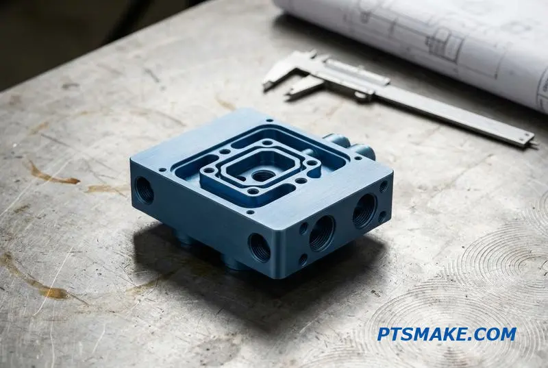
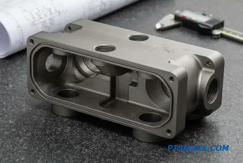
Coolant Distribution Manifolds: Precision Flow Control in a Tight Rack
In modern data centers, managing heat in tightly packed racks is a major challenge. Coolant distribution manifolds are critical components in liquid cooling systems, ensuring that every server gets the precise flow it needs. Without them, a system can easily overheat, leading to performance loss or hardware failure.
Key Design Considerations
The design of these manifolds directly impacts the reliability of the entire cooling loop. We focus on routing that minimizes pressure drop while maximizing flow distribution. Every port, channel, and connection point must be perfectly executed to prevent leaks and ensure consistent thermal management across the rack.
Material Choices
Choosing the right material is a balance between performance and cost. Each option offers distinct advantages for specific environments within liquid cooling systems.
| Material | Primary Benefit | Common Application |
|---|---|---|
| 6061-T6 Aluminum | Lightweight, good thermal conductivity | General purpose, weight-sensitive designs |
| 304/316L Stainless Steel | Excellent corrosion resistance | Systems with aggressive coolants |
Manufacturing a reliable coolant manifold requires more than just following a blueprint. The details of the liquid cooling manifold machining process are what separate a functional part from a flawless one. Precision is not just a goal; it’s a fundamental requirement for these critical components.
Precision Machining Requirements
Complex internal channels often demand multi-axis drilling to create intersecting cross-holes without burrs that could impede flow. O-ring grooves need a specific surface finish to create a perfect seal. An improper finish can cause slow leaks that are disastrous in a server rack environment. We also manage tight thread tolerances for standards like NPT, UNF, and ISO.
| Feature | Critical Tolerance | Reason for Precision |
|---|---|---|
| Port Center Position | ±0.1 mm | Rack-level blind-mate alignment |
| O-Ring Groove Finish | 1.6-3.2 μm Ra | Prevents fluid leaks under pressure |
| Thread Form | Per NPT/UNF/ISO standards | Guarantees secure, leak-proof fitting connections |
Blind-Mate Designs and Testing
In large-scale systems following OCP standards, blind-mate manifolds are common. This means the connections must align perfectly without visual confirmation. This is why positional tolerances are so tight. After machining, we conduct rigorous pressure testing, typically holding 10-15 bar to ensure a leak rate below 0.1 cc/min. For aluminum parts, a process like anodization5 is often specified to improve surface hardness and corrosion resistance.
Precision machining, correct material selection, and rigorous testing are essential for creating coolant distribution manifolds. These parts must deliver reliable, leak-proof performance to protect sensitive electronics in high-density liquid cooling systems, ensuring optimal operation within tight server rack constraints.
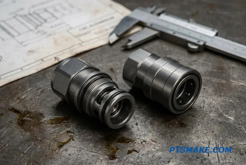
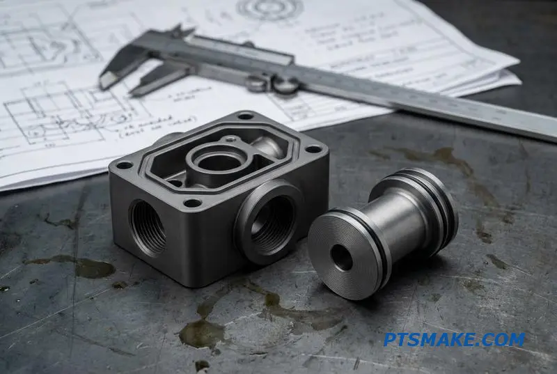
Quick-Disconnect Couplings and Fittings: The Leak-Prevention Challenge
In high-performance liquid cooling systems, every connection is a potential failure point. Quick-disconnect couplings must provide fast, reliable links, but their complexity introduces risks. Even a minor leak can cause catastrophic damage to sensitive electronics, making component integrity essential.
The Most Vulnerable Components
The primary challenge lies in the precision of the coupling’s internal parts. The body, poppet, and sleeve must interact flawlessly to ensure a perfect seal upon connection and disconnection. Threaded fittings also require exact tolerances to prevent leaks under pressure.
Sealing Geometry is Everything
The design of the sealing faces is critical. Whether it’s a ball-and-cone or flat-face design, the mating surfaces must be perfect. Any microscopic imperfection can create a leak path, compromising the entire system’s reliability.
The secret to a leak-proof coupling is not just design but manufacturing precision. For any CNC turned quick disconnect fitting, the focus must be on the internal valve mechanism, often a dry-break design that prevents fluid loss during disconnection.
The Role of Swiss-Type CNC Turning
For these small, complex parts, Swiss-type CNC turning is my preferred method. It provides exceptional stability for long, slender components like poppets, ensuring tight concentricity and dimensional accuracy. This precision is vital for creating the critical sealing geometries required in liquid cooling coupling machining.
Material Selection and Surface Finish
Material choice impacts both performance and longevity. We often work with stainless steel, brass, and PEEK, each offering distinct advantages. Based on our tests, the final surface finish on sealing faces is non-negotiable.
| Material | Key Advantage | Common Application |
|---|---|---|
| 303/316 SS | Corrosion Resistance | High-pressure, demanding environments |
| Brass | Cost-Effective & Machinable | General-purpose cooling loops |
| PEEK | Lightweight & Chemical Inertness | Medical or specialized electronic systems |
A surface finish of Ra 0.4µm or better is essential on any O-ring Gland6 or mating face. This specification, often aligned with standards like OCP UQD/BMQC, ensures the seal can perform without microscopic leaks developing over time.
Precision in manufacturing these components is paramount. The right material, machined with Swiss-type turning to exact tolerances and a flawless surface finish, directly determines the reliability of quick-disconnect fittings in critical liquid cooling systems.
CDU Chassis and Structural Components: Large-Part Machining Considerations
When machining large structural parts for Liquid Cooling Systems, key decisions shape the final product’s integrity. We often handle enclosure panels, mounting plates, and frames, typically from aluminum or stainless steel. A primary consideration is choosing between a weldment and machining from a solid block.
Weldment vs. Machined-from-Solid
This choice impacts cost, lead time, and structural performance. A weldment can be more material-efficient, but machining from solid offers superior stability and precision, eliminating weld-induced stress and distortion.
| Feature | Weldment Assembly | Machined from Solid |
|---|---|---|
| Material Cost | Lower | Higher |
| Stability | Prone to distortion | Excellent |
| Precision | Good, but limited | High |
| Lead Time | Can be longer | Often shorter |
Component Mounting and Flatness
Precise tapped hole patterns are crucial for mounting pumps and heat exchangers. Maintaining flatness, often specified as 0.1mm over 300mm, is a significant challenge that directly influences our fixturing and machining strategy.
The debate between weldments and solid machining for data center cooling structural parts often comes down to tolerance requirements. While weldments seem cost-effective, the heat-affected zones can introduce unpredictable warping, making it difficult to hold tight flatness and positional tolerances for mounting holes.
The Impact of Material Stress
For large aluminum plates, internal Residual Stress7 from the manufacturing process can be a major issue. As we machine material away, this stress is released, causing the part to bow or twist. This directly compromises the required flatness. Proper fixturing is essential, but it can only do so much.
Stress Relief and Fixturing Strategies
To counteract this, we often recommend a multi-step process. This includes rough machining, followed by a stress-relief heat treatment, and then a final finishing pass. Our fixturing techniques are designed to clamp the part securely without introducing new stresses, ensuring the final component for the CDU chassis meets all geometric specifications. At PTSMAKE, we’ve developed methods that minimize deformation during this critical process.
Machining large CDU structural parts requires a careful balance between cost, stability, and precision. The choice between a weldment and a solid block, combined with meticulous stress management and fixturing, is crucial for achieving tight flatness tolerances and ensuring reliable component assembly.
Material Selection for Liquid Cooling Components: Compatibility Matters
Selecting the right materials for liquid cooling systems is critical for performance and long-term reliability. Each component serves a distinct purpose, and its material must be chosen accordingly. The goal is to balance thermal performance, structural integrity, and cost, while preventing system failure.
Component-Specific Choices
For cold plates, where heat transfer is paramount, copper is the clear winner due to its high thermal conductivity. For structural parts like manifolds, aluminum offers a great mix of machinability and cost-effectiveness.
Material Overview
Below is a quick guide I use for initial selection.
| Component | Recommended Material | Key Benefit |
|---|---|---|
| Cold Plates | Copper (C110) | Thermal Conductivity (>380 W/m·K) |
| Manifolds / CDU Parts | Aluminum 6061-T6 | Cost-Effective & Machinable |
| Fittings / QDs | 316L Stainless Steel | Corrosion Resistance |
| Seals / Insulators | PEEK / PTFE | Chemical Inertness |
Beyond individual performance, material interaction within the coolant loop is crucial. A high-performance system can quickly fail if its components are not chemically compatible. This is why a holistic approach to CNC machining materials for liquid cooling is non-negotiable in my work at PTSMAKE.
Fittings, Seals, and Compatibility
For fittings and quick disconnects, I recommend 316L stainless steel. It offers excellent corrosion resistance, especially with common water-glycol coolants. For seals and insulators, plastics like PEEK or PTFE are ideal due to their chemical inertness and stability at various operating temperatures.
Managing Electrochemical Reactions
Mixing dissimilar metals, such as copper and aluminum, in the same coolant loop is a common mistake. It establishes a potential difference because of their varying Electromotive Force8. This drives an electrochemical reaction that degrades the less noble metal, leading to leaks and system failure.
| Treatment | Base Material | Purpose |
|---|---|---|
| Nickel Plating | Copper | Create a non-reactive barrier |
| Anodizing | Aluminum | Enhance corrosion resistance |
| Passivation | Stainless Steel | Improve surface stability |
Surface treatments are a practical solution. Nickel-plating copper or anodizing aluminum creates a protective barrier, allowing you to use the best material for each job without risking corrosion.
In summary, effective material selection for liquid cooling involves matching materials to their function—like copper for heat transfer and aluminum for structure. Ensuring electrochemical compatibility, often through protective surface treatments, is essential for building reliable, long-lasting systems.
Tolerance and Surface Finish Requirements for Leak-Free Sealing
In liquid cooling systems, preventing leaks comes down to precision. It’s not just about the design but about the microscopic details of the machined parts. Achieving a perfect seal depends entirely on controlling dimensional tolerances and surface finish. These factors dictate how well two surfaces mate.
Key Dimensional Tolerances
For reliable sealing, specific dimensions must be held to tight tolerances. O-ring grooves, for example, require precise depth and width to ensure correct compression. If a groove is too deep, the O-ring won’t compress enough; too shallow, and it could be damaged.
Common Specifications
Here are some typical tolerances we work with for liquid cooling components at PTSMAKE.
| Feature | Typical Tolerance | Purpose |
|---|---|---|
| O-ring Groove Depth | ±0.05 mm | Ensures proper O-ring compression |
| Seal Face Flatness | 0.01 mm | Prevents gaps in metal-to-metal seals |
| Thread Class Fit | 2A/2B Minimum | Guarantees secure, leak-proof connections |
Surface Finish Standards
The texture of a sealing surface is just as important as its dimensions. A rough surface can create tiny paths for fluid to escape, leading to leaks over time.
A common mistake is assuming a smoother surface is always better. The optimal surface finish depends on the sealing method. The right texture helps the seal material conform and hold pressure effectively, which is essential for high-performance liquid cooling systems.
Matching Finish to Sealing Method
Different seals demand different surface characteristics. For instance, a soft compression gasket benefits from a slightly rougher surface (Ra 0.8 μm) to bite into. This creates a stronger mechanical lock and prevents the gasket from slipping under pressure or thermal cycling.
An O-ring, however, needs a smoother gland surface (Ra 1.6 μm) to avoid abrasion during installation and operation. In contrast, metal-to-metal seals require an exceptionally smooth finish (Ra 0.4 μm) and high Flatness9 to achieve a bond without any gasket material.
Why Surface Roughness Dictates Leak Rate
Surface roughness, or Ra, measures the microscopic peaks and valleys on a part’s surface. These tiny imperfections can form a continuous leak path if not properly controlled. After running several tests, we’ve confirmed that a rougher-than-specified surface directly increases the potential leak rate under pressure.
This is why Coordinate Measuring Machine (CMM) inspection reports are not just paperwork. They provide documented proof that critical features like flatness and groove dimensions meet the print. At PTSMAKE, we supply these reports to ensure our clients have full confidence in every part.
For leak-free liquid cooling systems, success is in the details. Precise dimensional control and specified surface finishes are non-negotiable. These factors work together to create a reliable seal that performs under pressure and over time, preventing costly failures.
Leak Testing and Quality Assurance for Cooled Server Components
In AI data centers, a component failure isn’t just a defect; it’s a potential catastrophe. That’s why our quality assurance for cooled server components is non-negotiable. Every part must meet stringent leak-proof standards before it ever leaves our facility. This requires a multi-faceted approach.
Key Testing Protocols
We rely on several critical tests to validate integrity. Each serves a specific purpose, from detecting microscopic leaks to ensuring a component can withstand operational pressures. This ensures robust performance for demanding liquid cooling systems in the field.
| Test Type | Purpose | Typical OEM Requirement |
|---|---|---|
| Helium Mass Spectrometer | Detects micro-leaks | <1×10⁻⁶ mbar·L/s |
| Pressure Decay | Verifies seal integrity over time | No detectable pressure loss |
| Hydrostatic Proof | Confirms structural strength | Withstand 1.5x working pressure |
For AI data center OEMs, CNC machined parts quality control goes far beyond simple measurements. It requires integrating advanced testing protocols directly into the production flow to guarantee reliability. We don’t just inspect parts at the end; we build quality in at every stage.
Integrating Testing into Production
Testing is scheduled at critical milestones. For instance, initial checks occur after machining to identify any material porosity before we invest time in assembly. The most rigorous tests, however, are performed on fully assembled components like cold plates, ensuring all seals and joints are perfect.
Sampling Strategies and Validation
Our approach to sampling is risk-based. For critical components that directly handle fluid, such as cold plates and quick-disconnects (QDs), we perform 100% leak testing. For structural components, a statistically significant AQL sampling plan is sufficient.
This is complemented by CMM or Faro Arm inspections. These tools validate critical dimensions, because a dimensional flaw can easily lead to a leak. For example, the hydrostatic proof test relies on Pascal’s principle10 to evenly distribute pressure, which can expose weaknesses if a part’s geometry is not perfect.
Effective quality assurance for liquid cooling systems combines leak testing, pressure validation, and precise dimensional inspection. This integrated process, applied throughout CNC production, is essential for delivering components that meet the zero-failure tolerance required in today’s data centers.
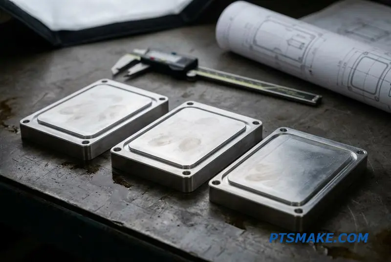
Prototyping vs Production: Matching CNC Process to Volume
Choosing the right CNC machining approach is crucial for managing costs and timelines. The strategy for making one prototype is completely different from making a thousand parts. The key is to match the process to your required volume, especially for components in complex assemblies like liquid cooling systems.
The Prototyping Stage (1-50 Pieces)
For initial prototypes, speed is the priority. The goal is to get a functional part for testing as quickly as possible. We typically machine from a solid block of material using straightforward programming to minimize setup time and allow for rapid design changes.
Milling from Solid
This approach offers maximum design flexibility. We can create complex geometries for components like a liquid cooling cold plate without investing in custom tooling. The focus is on verifying form, fit, and function, not on optimizing for mass production speed.
| Approach | Best For | Key Benefit |
|---|---|---|
| 3-Axis Milling | Simpler geometries, faster setup | Cost-effective and quick for initial concepts |
| 5-Axis Milling | Complex curves and features | Reduces setups, machines intricate parts in one go |
Low-Volume Production (50-1,000 Pieces)
Once the design is validated, we shift focus to efficiency. For these quantities, optimizing the manufacturing process becomes essential to reduce cost per part. It’s about finding a balance between setup time and machining speed.
Optimizing for Repeatability
At this stage, we move from one-off setups to creating repeatable processes. We develop dedicated fixtures to hold parts securely and consistently. This reduces operator error and ensures that the 500th part is identical to the first. Optimizing tool paths also becomes critical to reduce cycle time.
High-Volume Production (1,000+ Pieces)
For high volumes, the strategy changes completely. The goal is to minimize cycle time and material waste. Every second saved on a single part translates into significant cost savings across the entire production run. This is where specialized machinery and alternative processes come into play.
Evaluating Alternative Processes
At PTSMAKE, when a project scales, we evaluate if a hybrid approach is better. For a complex liquid cooling manifold, machining from solid is too slow and wasteful. Instead, we might suggest casting the near-net shape and then using CNC machining for the critical features and mating surfaces. This established a stable Datum11 for all subsequent high-precision operations.
| Volume | Primary Goal | Common Techniques |
|---|---|---|
| 1 – 50 | Speed & Iteration | 3/5-Axis Milling from Solid |
| 50 – 1,000 | Efficiency & Repeatability | Optimized tool paths, custom fixtures |
| 1,000+ | Cost & Cycle Time Reduction | Multi-spindle lathes, casting + finish machining |
Matching your CNC machining process to the production volume is essential for success. Prototyping prioritizes speed, low-volume focuses on creating repeatable efficiency, and high-volume production demands deep optimization for cost and speed, often incorporating hybrid manufacturing methods for the best results.
5-Axis CNC Machining for Complex Cooling Geometries
Modern liquid cooling systems demand intricate designs that traditional machining cannot produce efficiently. 5-axis CNC machining directly addresses this need, enabling the creation of highly complex geometries in a single setup. This capability is crucial for maximizing thermal performance.
Enhanced Cooling Performance
Features like compound-angle coolant ports and complex internal passages are key. They improve flow dynamics and surface area contact. 5-axis machining makes these designs possible, moving beyond the limits of 3-axis methods and enhancing component efficiency.
Consolidating Production
By completing parts in one clamping, we reduce setup time and potential for error. This is especially true for cold plates with features on multiple faces. The result is better accuracy and faster delivery for critical cooling components.
The main decision for multi-axis machining cooling components is between 3+2 positioning and full 5-axis simultaneous motion. While both use a 5-axis machine, their applications differ significantly. Understanding this helps justify the investment in more advanced manufacturing processes.
3+2 vs. Full 5-Axis Simultaneous
3+2 axis machining, or positional machining, locks the workpiece at a compound angle. The machine then performs 3-axis operations. This is great for drilling angled holes or machining pockets on tilted faces. It’s often faster and more cost-effective for these specific features.
Full simultaneous 5-axis machining involves continuous movement of the tool and workpiece. This is essential for creating complex contours, undercut features, and smooth, blended internal passages found in advanced manifolds. It eliminates the sharp edges left by positional strategies, improving coolant flow. This process relates directly to machine kinematics12.
Practical Application Comparison
Based on our tests, full 5-axis motion can reduce cycle times by up to 25% on parts with complex curved surfaces compared to multiple 3+2 setups. The premium is justified when fluid dynamics are critical.
| Machining Type | Best For | Cycle Time | Surface Finish |
|---|---|---|---|
| 3+2 Positional | Compound-angle ports, angled pockets | Lower for simple features | Good, but with potential step marks |
| Full 5-Axis | Blended internal passages, undercuts | Higher for simple features | Superior, continuous finish |
5-axis CNC machining unlocks complex geometries for high-performance liquid cooling systems. The choice between 3+2 and full simultaneous motion depends on the feature’s complexity, required surface finish, and overall performance goals, justifying the investment for critical applications.
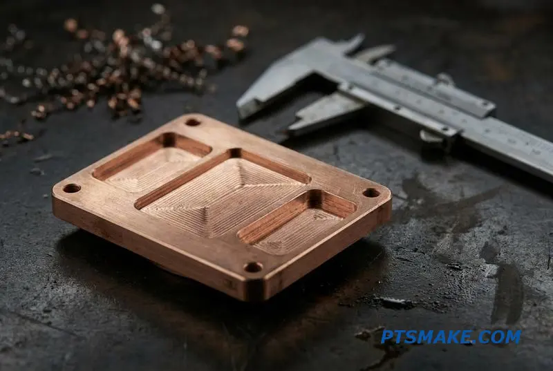
Surface Finish and Post-Processing for Coolant Channel Integrity
After machining, the work on a cold plate is far from over. Post-processing steps are not optional; they are critical for the reliability of high-performance liquid cooling systems. Neglecting them can lead to system failure. These processes ensure coolant channels are clean, smooth, and protected from corrosion.
The Importance of Deburring
Burrs are small, sharp pieces of metal left over from machining. If they break loose, they can clog narrow coolant channels or damage sensitive components like pumps. Proper deburring is essential for clean and reliable coolant channel finishing.
| Deburring Method | Best For | Key Consideration |
|---|---|---|
| Manual | Simple geometries, low volume | Labor-intensive, potential for inconsistency |
| Thermal | Complex internal channels | Requires precise control to avoid part damage |
| Electrochemical | High-precision, hard-to-reach areas | Higher initial cost, material-specific |
Final Cleaning Protocols
Even microscopic residues from cutting fluids or cleaning agents can cause problems over time. We implement ultrasonic cleaning as a final step. This process uses high-frequency sound waves to remove contaminants from deep within the coolant channels, ensuring the part is pristine before assembly.
Proper post-machining processing directly impacts long-term performance. For parts in liquid cooling systems, surface treatments are vital for preventing corrosion, which can degrade thermal efficiency and cause leaks. The right treatment depends on the base material and the type of coolant used.
Passivation for Stainless Steel
For stainless steel components, we use passivation. This is a chemical process that removes free iron from the surface. It enhances the natural corrosion resistance of the steel by forming a passive oxide layer. This is crucial for preventing rust particles from contaminating the cooling loop.
Plating for Copper and Aluminum
When using copper or aluminum cold plates, especially in mixed-metal systems with water-glycol coolants, corrosion is a significant risk. Electroless nickel plating provides a uniform, protective barrier. This coating prevents direct contact between the coolant and the base metal, offering a form of Cathodic Protection13.
| Treatment | Base Material | Primary Benefit |
|---|---|---|
| Passivation | Stainless Steel | Enhances natural corrosion resistance |
| Electroless Nickel | Copper, Aluminum | Creates a protective barrier, prevents galvanic corrosion |
We specify plating thickness carefully, as it must be thick enough for protection but not so thick that it negatively impacts thermal performance. These details are vital for cold plate post-machining processing.
Effective post-processing, including deburring, passivation, and plating, is crucial for coolant channel integrity. These steps prevent blockages and corrosion, directly enhancing the reliability and performance of liquid cooling systems and ensuring long-term operational stability for the final product.
Cost Drivers in CNC-Machined Liquid Cooling Parts
Understanding the cost drivers for CNC-machined liquid cooling parts is crucial for effective budgeting. The primary factors are material choice, machining complexity, and finishing requirements. Each decision directly influences the final pricing of your liquid cooling systems.
Material Selection
Material is a significant part of the cost. Aluminum is a common baseline due to its good thermal conductivity and machinability. Copper offers superior performance but at a higher material and machining cost.
Material Cost Comparison
| Material | Relative Material Cost (Aluminum = 1x) | Thermal Conductivity (W/mK) | Notes |
|---|---|---|---|
| Aluminum (6061) | 1x | ~167 | Excellent balance of cost and performance. |
| Copper (C110) | 2x – 3x | ~385 | Best thermal performance, but heavier. |
| Stainless Steel (304) | 1.5x – 2x | ~16 | Used for corrosion resistance, not performance. |
Machining and Finishing
Simple designs with drilled channels are the most cost-effective. However, complex geometries like microchannels or 5-axis manifolds increase machine time and tooling costs, directly impacting the CNC machining cost of a cold plate.
Let’s delve deeper into how design choices affect liquid cooling parts pricing. Machining complexity is not just about the shape; it’s about the number of setups, specialized tooling, and operator time required for the component.
Design Complexity Impact
A simple cold plate might only require a 3-axis mill. A manifold with intricate internal passages, however, often demands 5-axis simultaneous machining to achieve the required geometry, which significantly increases hourly machine rates and programming time.
Machining Complexity vs. Cost
| Feature Complexity | Machining Approach | Relative Cost Impact |
|---|---|---|
| Simple Drilled Channels | 3-Axis CNC Milling | Baseline |
| Complex Internal Passages | 3-Axis + Multiple Setups | +50% to +150% |
| Microchannel Features | Specialized Tooling/Process | +100% to +300% |
| Integrated Manifolds | 5-Axis CNC Milling | +200% to +500% |
Design for Manufacturing (DFM)
To manage costs, apply DFM principles. Avoid unnecessarily tight Tolerancing14 where it is not functionally critical. Simplifying internal passages and standardizing thread types can also reduce manufacturing time and cost. Finally, production volume has a major impact, with per-part costs decreasing significantly as quantities increase due to setup cost amortization. At PTSMAKE, we guide our partners through these DFM choices.
Key cost drivers for liquid cooling systems are material, machining complexity, and tolerances. Smart design choices and considering production volume are essential for managing your budget effectively without compromising the necessary performance of the final parts.
Design for Manufacturing: Optimizing Your Cooling Part Drawings for CNC
Optimizing your drawings for CNC machining is crucial for creating effective liquid cooling systems. Simple adjustments can significantly reduce costs and lead times. Clear DFM for liquid cooling CNC parts prevents misinterpretation and ensures the final component functions as intended. It’s about communicating effectively with your manufacturing partner.
General DFM Rules for Cooling Parts
Avoid sharp internal corners, as these require specialized tooling or processes. Instead, specify a radius that accommodates a standard end mill. Also, clearly define thread depths and provide clear datum surfaces for accurate setups. This clarity removes guesswork during production.
Sealing and Positional Tolerances
It’s vital to call out the finish for sealing surfaces separately from the general surface finish. Sealing areas require a specific texture for proper function. Avoid unnecessarily tight positional tolerances on non-critical features, like mounting holes, as this drives up machining time and cost without adding value.
| Feature | Common Mistake | DFM Recommendation |
|---|---|---|
| Internal Corners | 90-degree sharp corner | Specify a radius (e.g., 1mm or larger) |
| Threads | "M4 thread" | "M4x0.7, 8mm full thread depth MIN" |
| Tolerances | ±0.01mm on all holes | Loosen tolerance on non-critical holes |
When designing a cold plate, the internal coolant channels are the most critical feature. Your design must account for tool access. Complex, winding paths that a cutting tool cannot physically reach are impossible to machine directly. We often see designs that look great in CAD but are unmanufacturable.
Designing Manufacturable Cold Plates
A key part of the design for manufacturability cold plate is simplifying the coolant path. Consider how an end mill will enter and move through the material. Straight channels or gentle curves are always more cost-effective. If complex paths are necessary, a modular design might be a better approach.
Modular Designs and Surface Finishes
Breaking a complex cold plate into multiple, simpler components that are later assembled can be very effective. This approach simplifies fixturing and machining operations for each piece. For sealing O-rings or gaskets, the Surface Roughness15 is paramount. A specific, smooth finish in the groove prevents leaks, and this requirement should be clearly noted on the drawing.
| Design Element | Consideration | Impact on Manufacturing |
|---|---|---|
| Coolant Channels | Tool diameter and length | Determines feasibility and machining time |
| Fixturing | Part complexity and stability | Influences setup time and part accuracy |
| Sealing Surfaces | Finish callout (Ra value) | Critical for leak-proof performance |
Optimizing your drawings with DFM principles is key for successful liquid cooling parts. By specifying corner radii, clear datums, and appropriate tolerances, you streamline production. For cold plates, focusing on tool access and smart surface finish callouts ensures functionality and cost-effectiveness.
Aerospace vs Data Center: What Liquid Cooling Machining Can Learn From Each
While seemingly worlds apart, aerospace and data center liquid cooling systems share a core dependency on precision machining. One field protects critical flight systems, while the other enables the AI revolution. Yet, their manufacturing priorities diverge significantly.
Core Requirement Divergence
Aerospace demands absolute, documented reliability. Data centers, however, prioritize rapid scalability and cost-efficiency. Understanding these differences is key to optimizing manufacturing for both.
| Industry | Primary Focus | Key Challenge |
|---|---|---|
| Aerospace | Reliability & Safety | Extreme Environments |
| Data Center | Scalability & Cost | Rapid Tech Cycles |
Both sectors converge on one non-negotiable point: leak integrity. A failure in either environment is catastrophic.
The contrast in manufacturing standards becomes clear when you look at the details. Each sector has unique demands that shape the entire production process, from material selection to final inspection.
Aerospace: The Gold Standard
For aerospace liquid cooling machining, MIL-spec standards are the law. This involves extensive documentation for material traceability and process validation. We often work with exotic alloys chosen for their strength-to-weight ratio and resistance to extreme temperatures. Think avionics cold plates that must perform flawlessly at 30,000 feet.
Data Center: The Efficiency Engine
In contrast, data center cooling manufacturing standards are driven by cost and speed. Materials are typically aluminum alloys, optimized for thermal conductivity and ease of manufacturing. The goal is to produce reliable, leak-proof systems at a massive scale, with designs that can be iterated quickly to match new server hardware. We’ve found that materials must have uniform, Isotropic16 properties to manage thermal expansion consistently across thousands of units.
| Aspect | Aerospace Standards | Data Center Standards |
|---|---|---|
| Material | Exotic alloys (e.g., Inconel) | Aluminum (e.g., 6061) |
| Documentation | Extensive (MIL-STD) | Lean (Internal QA) |
| Iteration Speed | Slow, methodical | Fast, agile |
| Cost Focus | Performance over cost | Cost-per-unit is critical |
At PTSMAKE, our experience across both fields provides a unique advantage. We apply aerospace-level precision to data center projects and bring cost-efficiency insights to our aerospace work.
Though aerospace requires rugged, MIL-spec compliance and data centers need cost-effective scalability, both rely on precision machining for leak-proof liquid cooling systems. This shared foundation of reliability is where our expertise delivers value across industries.
Future Trends: Cold Plate Miniturization, Two-Phase Cooling, and Embedded Microfluidics
The future of thermal management is shrinking. We are moving away from traditional, bulky cold plates toward highly integrated solutions. This evolution is driven by the intense heat generated by next-generation AI and high-performance computing chips, demanding more efficient heat dissipation.
Key Evolutionary Steps
The industry’s direction is clear. We are seeing a push toward two-phase cooling for higher efficiency and embedded microfluidics for direct-to-chip thermal management. These shifts require a complete rethinking of manufacturing processes to achieve the necessary complexity and precision.
| Cooling Technology | Current State | Future Direction |
|---|---|---|
| Form Factor | External Cold Plates | Embedded Microchannels |
| Cooling Method | Single-Phase (Liquid) | Two-Phase (Evaporative) |
| Integration | System-Level | Chip-Substrate Level |
The next wave of liquid cooling systems will be defined by their manufacturing complexity. Two-phase cooling, for instance, relies on intricate internal channel geometries to manage the liquid-to-vapor transition efficiently. Any surface imperfection or dimensional error can disrupt this delicate process, leading to system failure.
Manufacturing for Tomorrow’s Cooling
This is where precision becomes paramount. Respected research, like that from Microsoft on Microfluidics17, points toward cooling channels embedded directly into chip substrates. These features are often smaller than 100 micrometers. Based on our collaborations with clients in this space, achieving such designs consistently is a major hurdle.
Newer additive techniques, like Fabric8Labs’ ECAM, show potential for creating complex cold plates. However, CNC machining is the critical bridge technology. It delivers the ±0.005mm tolerances required for today’s advanced prototypes while being adaptable enough to machine the molds and tooling for tomorrow’s integrated cooling solutions.
| Future Trend | Manufacturing Implication | CNC Machining’s Role |
|---|---|---|
| Two-Phase Cooling | Leak-proof, complex internal channels | Prototyping, final machining |
| Embedded Microfluidics | Sub-100µm channel fabrication | High-precision tooling, direct machining |
| Chassis Integration | Tightly toleranced, custom paths | Creating reliable interface surfaces |
Future liquid cooling systems hinge on manufacturing innovation. Miniaturization, two-phase designs, and embedded channels demand unprecedented precision. CNC machining is the foundational technology that enables the development and production of these next-generation thermal management solutions.

Understanding this fluid dynamic principle is key to designing high-performance liquid cooling systems for maximum heat dissipation. ↩
Understanding this helps prevent material stress and leaks in components under thermal cycling. ↩
Understanding this electrochemical process is crucial for preventing premature failure in mixed-metal liquid cooling systems. ↩
Understanding Heat Flux helps in designing effective thermal solutions for high-performance electronics. ↩
Discover how this electrochemical process enhances surface properties for better durability. ↩
Understanding gland design is crucial for ensuring proper O-ring compression and preventing seal failure in high-pressure applications. ↩
Understanding this concept helps prevent part deformation and ensures long-term stability in precision assemblies. ↩
Understanding this concept helps predict and prevent material corrosion when different metals are used in a fluid system. ↩
Understand how this geometric control is measured and its vital role in high-pressure sealing applications. ↩
Understand the fundamental physics that validates hydrostatic pressure testing for component integrity. ↩
Understanding datums ensures design intent is maintained from prototype to production. ↩
Understanding machine kinematics helps optimize toolpaths for better surface finish and reduced machining time. ↩
Understanding this principle helps select coatings that prevent corrosive failure in multi-metal systems. ↩
Explore how precise tolerancing ensures component fit and function while impacting manufacturing costs. ↩
Learn how controlling surface texture is critical for preventing leaks and ensuring the reliability of your liquid cooling systems. ↩
Learn how this property ensures material stability under thermal stress, preventing part failure. ↩
Understanding microfluidics is key to grasping how fluid dynamics at the micrometer scale will redefine thermal management. ↩