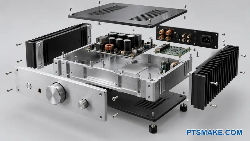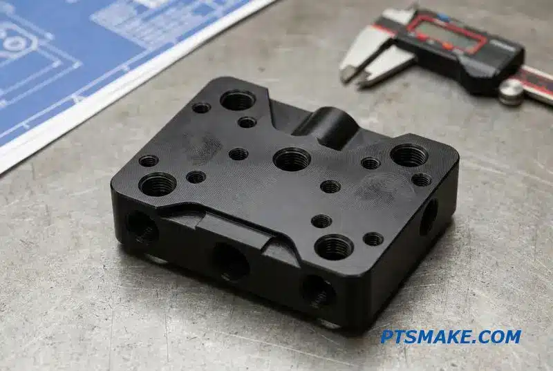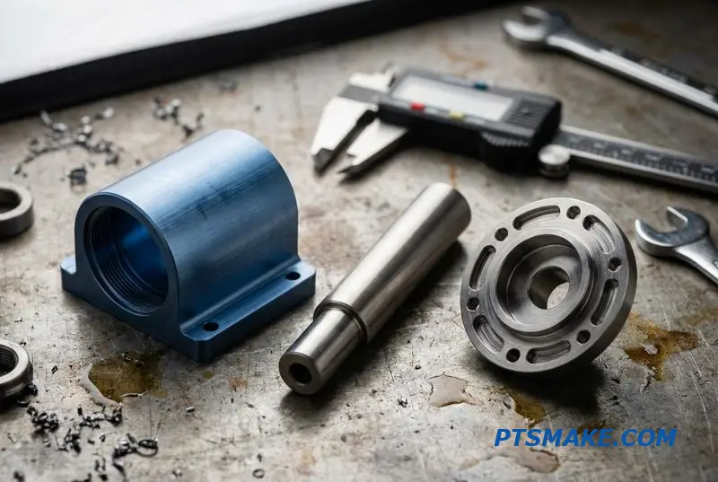

A spotlight housing can look simple, but weak datum, thermal, sealing, or finish choices can cause beam shift, heat buildup, leaks, and expensive rework.
Quick answer: Good machined aluminum spotlight housings use one functional datum system for the LED, optic, lens, seal, and mounting features. The design also needs a short heat path, clear cutter access, finishing allowances, and defined inspection methods before production.
The review order below follows the way each decision affects the next one. This sequence protects optical and enclosure performance while giving the CNC supplier enough freedom to reduce risk and cost.
Send your drawing for a focused spotlight housing DFM review.
Define the Engineering Inputs Before You Shape the Housing
Start with the product conditions
Every spotlight housing DFM review starts with the product conditions. A clean solid model does not show the full engineering problem. It does not explain the beam target, LED heat load, outdoor exposure, mounting load, cleaning method, or expected service work. Those conditions decide which surfaces must stay stable and which shapes can change.
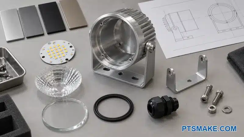
The design team should identify the LED package and board. The review also needs the optic or reflector part number, lens stack, seal concept, cable entry, bracket, driver location, intended finish, and use environment. A housing for a dry indoor display has different risks from a housing that faces rain, salt, dust, vibration, or frequent aiming.
Separate fixed inputs from open choices
Each input receives one of three labels: fixed, preferred, or open. This simple classification prevents a style choice from becoming an expensive hidden requirement. It also prevents a supplier from changing a critical interface because the drawing did not explain its purpose.
| Input status | What it means | DFM response |
|---|---|---|
| Fixed | Product function, safety, certification, or a purchased component controls it | We protect the interface and define verification |
| Preferred | The team wants the condition, but another solution may work | We compare cost, risk, and appearance before release |
| Open | The supplier may propose a better form or process | We state the design goal and an acceptable boundary |
The input sheet also records quantity, launch timing, and likely production life. Those facts change the right stock form and fixture investment. A prototype may justify flexible workholding. A repeating production order may justify dedicated soft jaws or a checking fixture.
The customer does not need to freeze every decision before DFM starts. The team only needs to show which decisions remain open. That distinction keeps the review honest. It also lets our engineers at PTSMAKE suggest a practical route without making an unsupported product decision.
Build one input sheet
One short input sheet works better than facts scattered through email. The sheet can point to controlled drawings and supplier data. It should show the current revision and owner for each open item. This approach reduces the chance that machining begins with an old optic file or an unapproved gasket.
Map Every Interface and Its Failure Consequence
Treat the housing as a system of interfaces
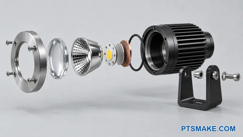
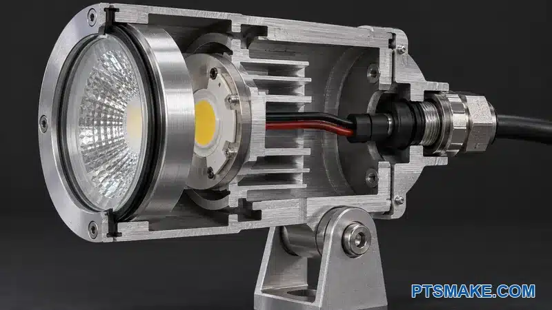
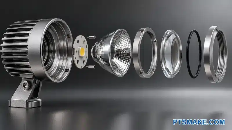
A machined aluminum spotlight housing is not just one block of metal. It contains an optical interface, a thermal interface, a sealing interface, a structural interface, and several assembly interfaces. One machined face may serve two functions, but the team must know both functions before it changes the face.
The LED board touches a thermal land. The optic locates from a bore or shoulder. The lens presses a seal. The pivot boss transfers aiming and locking loads. The cable gland closes another path into the enclosure. Each interface can pass a dimensional inspection and still fail in the assembled light if the surrounding stack is wrong.
The LED Luminaire Lifetime Guide1 explains that LED luminaire life depends on more than the LED package. Thermal management, optical elements, seals, and other system parts can control useful life. That system view is why I map interfaces before I assign tight tolerances.
Rank the consequence before the dimension
A short failure map gives the DFM meeting a clear order. This map does not replace a formal design FMEA. The review starts with the interface, names the likely failure, and identifies the first physical control.
| Interface | Possible product effect | First design control | Useful verification |
|---|---|---|---|
| LED board to housing | Higher temperature or uneven heat flow | Flat, clean contact land and balanced clamp load | Flatness, contact pattern, thermal test |
| LED to optic | Beam shift, hot spot, or lower optical efficiency | Shared center and direct axial seat | Assembly check and beam test |
| Lens to housing | Water or dust path | Continuous gland and even compression | Visual check and leak test |
| Pivot boss to bracket | Aim drift, wear, or crack risk | Supported boss and defined fit | Dimensional and load review |
| Cover to body | Gap, distortion, or lost seal load | Datum-controlled flange and fastener pattern | Flatness and assembly check |
| Cable entry | Leak, strain, or difficult service | Defined thread, sealing face, and access | Gauge, torque, and leak test |
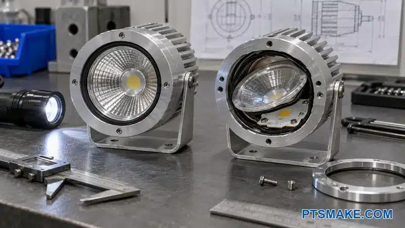
The next question is what can change after rough machining, finish machining, anodizing, assembly, and temperature cycling. This sequence often exposes a weak stack. For example, a lens seat may be concentric before finishing, but an unplanned coating on a locating diameter can change the fit.
Use the failure map to spend precision well
A general note such as “high precision required” does not help the shop. A consequence map does. It shows why the optical seat needs control while a hidden clearance pocket can remain flexible. It also gives the supplier a safe place to suggest a larger radius, a standard tool, or a different stock size.
The controls usually fall into three groups. The first group prevents function loss. The second protects assembly and service. The third protects appearance. All three groups matter, but they do not need the same measurement method or process margin.
Keep evidence tied to the actual product
Supplier documents and standards help frame the questions. A generic limit should not enter a drawing without a check against the selected LED, optic, seal, fastener, and environment. The product team owns functional acceptance. The machining team owns a capable manufacturing route. The interface map connects those responsibilities.
When PTSMAKE reviews a new housing, we can comment on machining access, datum transfer, finishing allowance, and inspection. We need the customer’s optical, thermal, sealing, and compliance targets to judge the final acceptance plan. That boundary prevents us from inventing product facts.
Choose a CNC Architecture That Matches the Shape and Volume
Read the dominant geometry first
The first architecture question is whether the housing is mainly round, mainly prismatic, or truly mixed. A round body with concentric steps can suit CNC turning. Live tools can add radial holes, flats, and slots. A box, yoke, or open frame may suit three-axis or four-axis milling. Angled optical faces and compound ports can make five-axis machining useful.
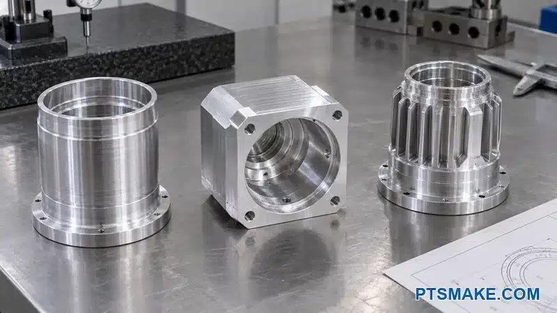
Access, datum retention, quantity, and inspection should drive the route. Five-axis machining is not the right choice only because a part looks complex. A stable three-axis process with two planned setups can be better for a simple body. A mill-turn route can be better when concentric faces and radial features must stay related.
Our CNC machining services include three-axis, four-axis, five-axis, turning, and mill-turn work. That range gives us options, but the part still needs a clear architecture. A machine cannot correct a weak datum plan or an inaccessible sealing face.
Compare one-piece and split-body designs
A one-piece body removes a joint and one possible leak path. It can also create a deep cavity, long tools, trapped chips, and difficult assembly. A split body opens the cavity and can simplify finishing. It also adds a flange, fasteners, tolerance stack, and seal.
Both concepts need comparison against function and total process risk. Fewer part numbers do not always mean lower cost. The one-piece option may save an assembly step but require slow deep-pocket machining. The split design may machine faster but require another controlled sealing interface.
Match investment to repeat volume
Prototype work benefits from adaptable fixtures and available stock. Repeated production can justify custom jaws, a tombstone, a dedicated gauge, or near-net stock. The expected volume also changes whether we combine operations or keep a simple process with clear inspection gates.
The PTSMAKE comparison of CNC machining and die casting for aluminum spotlight housings2 explains the larger process decision. This article assumes the team has selected CNC machining and needs to make that route stable.
Select the Alloy and Stock Form as One Decision
Balance heat, strength, finish, and supply
Many teams start with 6061 aluminum because it offers a useful balance for machined parts. The final choice still depends on the thermal model, pivot loads, finish, corrosion exposure, stock availability, and applicable specification. I avoid choosing an alloy from a single property table.
The aluminum alloy and temper standards3 maintained by the Aluminum Association help teams specify material in a shared language. The drawing or purchase package should state the required alloy, temper, and material specification. A loose note such as “aluminum” does not give purchasing or inspection enough control.
Review stock form at the same time
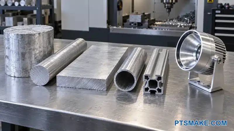
Plate, billet, round bar, tube, and extrusion do not create the same machining plan. They differ in available size, surface condition, grain direction, residual stress, waste, and lead time. A low price per kilogram can lose its advantage when most of the blank becomes chips.
| Design priority | Stock or material question | Review action |
|---|---|---|
| Stable optical geometry | Can heavy, uneven roughing release movement? | Review stock condition and staged machining |
| Anodized appearance | Can the alloy and stock route hold the approved look? | Approve samples from the intended process route |
| Thermal path | Does the alloy support the validated heat-flow model? | Confirm with the thermal owner |
| Pivot strength | Does the local boss carry clamp and service loads? | Review the boss and load path |
| Production cost | Can tube or extrusion remove roughing volume? | Compare total process cost, not material price alone |
Broad thermal lands, thin rings, and asymmetric housings need close attention. Heavy removal from one side can change the stress balance. A roughing step, rest period, stress-relieved plate, or revised stock shape may help. The right method depends on the part, so the supplier should describe the proposed route.
Control substitutions
An allowed substitute should match the product need, not only a general strength value. It may also affect anodized color, conductivity, corrosion behavior, cutting response, and supply documentation. I want every substitute approved before production material is cut.
At PTSMAKE, we machine common aluminum grades, but we do not treat them as visually or dimensionally identical. I recommend that the customer approves the actual alloy and finish route when color or surface consistency matters.
Build Functional Optical and Assembly Datums
Put the references on real mating features
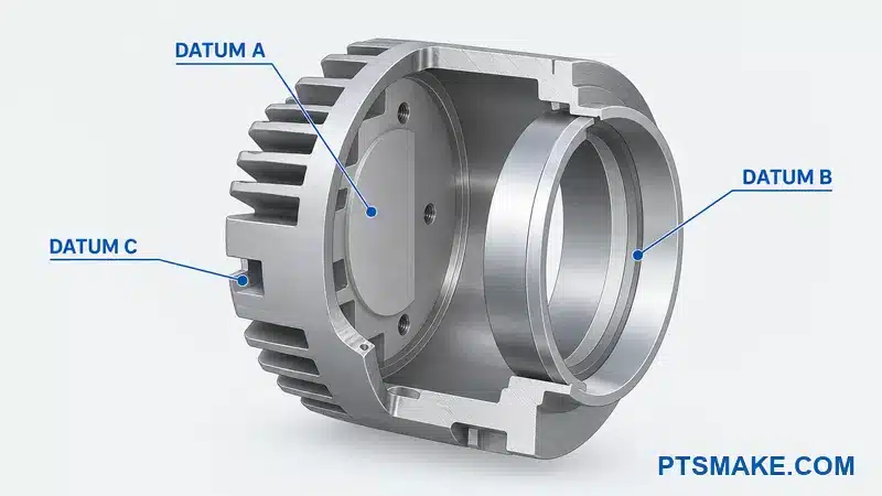
The datum plan usually starts with the surface that seats the LED board or optic carrier. That surface can create the primary plane. A controlled bore, pilot, or circular seat can then locate the optical axis. A pin, notch, or other feature can control rotation when cable or beam orientation matters.
A cosmetic outside cylinder can look like a natural reference. It is often weak if the LED, optic, and lens do not locate from it. The housing can look concentric while the optical stack remains displaced. A datum should represent assembly function before it represents visual symmetry.
Control six degrees of freedom
The primary plane should stop three motions. The secondary feature should locate two more. The tertiary feature should stop the final rotation or translation. This 3-2-1 idea is simple, but the actual features must be large, stable, accessible, and repeatable.
A tiny edge or flexible fin makes a weak datum target. A datum that disappears after a cover or bracket is installed creates the same problem. If assembly and inspection cannot recreate the reference, the drawing may be mathematically complete but operationally weak.
ASME Y14.54 defines a common system for dimensioning and geometric tolerancing. ISO 11015 defines the international language for geometrical controls. The drawing should identify its governing standard and edition because symbols need a shared interpretation.
Tie related features to one datum frame
The LED center, optic seat, lens seat, and front opening usually need a direct relationship. I try to connect those features to the same functional datum frame. I do not create separate coordinate systems for each component unless the product really uses separate locating systems.
The pivot can need another functional relationship. If beam direction must follow the pivot axis, the drawing should control that relationship. If the bracket only provides coarse aiming, a wider allowance may be enough. I use the failure map to choose.
| Feature | Functional question | Possible control approach |
|---|---|---|
| LED land | Does it set axial position and heat contact? | Primary datum and flatness based on interface need |
| Optic pilot | Does it set the beam center? | Position or run-out from the functional datum frame |
| Lens seat | Must it share the optical axis? | Direct location from the same frame |
| Clocking feature | Does rotation affect the beam or cable? | Profile or position from primary and secondary datums |
| Pivot bore | Does aim depend on its relation to the optical axis? | Orientation and position based on mounting function |
Make machining and inspection agree
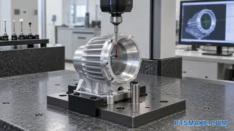
The process review asks how the part will be held for the critical operation and how inspection will establish the same datums. A coordinate measuring machine can calculate many relationships, but the fixture still needs stable access and a clear alignment method.
The drawing should not force the shop to inspect from a cosmetic shell when the machine and assembly use the thermal land. This mismatch adds argument without adding control. A good datum scheme lets design, machining, assembly, and quality discuss the same physical references.
In our DFM work, we often suggest small datum pads or a practical clocking feature when the original model lacks a repeatable reference. We only keep those features when they support the finished product, the fixture, or inspection. We do not add geometry only to make the CAD look technical.
The chosen references must also remain usable after anodizing and final assembly.
Design the LED Thermal Interface as a Complete Path
Start at the heat source
The thermal review follows the heat path from the LED junction to the surrounding air. That path can include the LED package, solder, board, thermal interface material, machined contact land, housing wall, finish, fins, and airflow. A change at any layer can affect the result.
The Lumileds thermal design white paper6 describes this path as a thermal resistance network and shows why each interface matters. A large external heat sink cannot correct a poor contact surface near the LED. The design needs both a low-resistance internal path and enough external area for the actual environment.
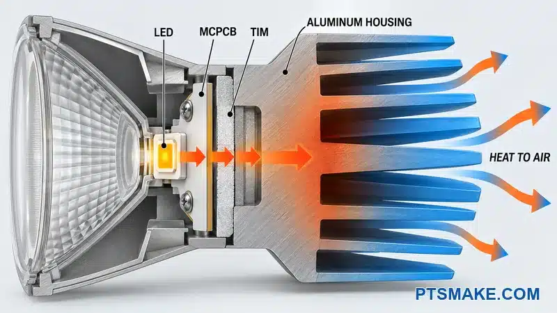
The thermal owner should provide the LED power condition, board type, interface material, allowed temperature, mounting position, airflow, and ambient range. A housing diameter alone cannot set a universal fin size. The product thermal owner should validate the final design under representative conditions.
Define the contact land as a functional interface
The board land needs enough area under the intended heat-spreading region. It also needs a controlled surface condition. Burrs, chips, coating, local dents, and a high spot near a screw can keep the board from sitting evenly.
The drawing should identify the contact zone and separate it from nearby cosmetic surfaces. If the land must remain free of anodizing or another coating, the drawing should define the mask boundary and acceptable transition. The process plan should also protect the bare aluminum from damage and contamination.
A very fine surface-finish value needs supporting evidence. Some thermal interface materials conform to machining marks. Some need a different condition. A finer finish can add cycle time and still fail if the land is not flat under the clamp load. The interface material supplier and thermal team should define the need.
Create a balanced clamp path
A flat land works only when the assembly holds the board against it. I place screws or clips so the clamp load reaches the active area without bending the board. I give each fastener a stiff local seat, enough driver access, and a repeatable tightening method.

The design should not let the board rock on solder joints, wire pads, or debris. Stand-offs and locating pins must not sit higher than the intended contact stack. The thermal interface layer also needs a defined thickness or compression condition. Extra material is not always safer because a thicker layer can add resistance.
| Thermal detail | Risk if unclear | DFM question |
|---|---|---|
| Contact land | Partial contact or board distortion | Which region must touch under assembly load? |
| Surface condition | Burr, coating, or debris creates a gap | What finish and cleanliness does the interface need? |
| Fastener pattern | Uneven pressure and local board bending | Does the pattern create a balanced clamp path? |
| Interface material | Excess thickness or incomplete coverage | What installed condition does the supplier require? |
| Wall to fins | Heat bottleneck near the source | Is the metal path continuous and thick enough? |
| External airflow | Fins work below expectation | Was the housing tested in its real orientation? |
Keep machining and thermal validation connected
The shop should explain how it will finish and protect the land. A broad land may need a staged operation after heavy cavity roughing. A thin housing can distort when clamped. A finish cut from the functional datum can help, but the fixture must support the part without bending it.
The separate PTSMAKE heat sink design guide covers the wider thermal design problem. For this housing, I keep the DFM focus on the contact land, metal path, fin machinability, finish boundary, and measurable acceptance criteria.
Machining alone does not prove thermal performance. We can make and inspect the defined geometry. The customer or test owner should confirm the assembled temperature under the intended electrical load and environment.
Ask PTSMAKE to review your LED contact land and machining route.
Keep the LED, Reflector, and Lens on One Optical Stack
Control center, height, and rotation
An LED can sit near the center and still produce the wrong beam. The optical stack needs radial control, axial control, and sometimes rotation control. The LED’s optical center may not match the center of its package or board outline. The selected component drawing must define the true locating references.
The LEDiL installation guide7 tells designers to align the LED optical center with the optical component. I use that requirement to review the mechanical stack. I do not assume that wide screw clearances can locate the board. Screws clamp well, but they usually make poor precision locators.
A direct machined pilot, locating edge, pin pattern, or controlled carrier is usually the clearest choice. The selected feature must match the component supplier’s allowed contact area. A pin that touches a sensitive circuit region can create a new problem even if it improves position.
Set axial height from a stable shoulder
The LED-to-optic distance can change focus and beam shape. I try to set this height from a direct machined shoulder and a short component stack. Soft gaskets, adhesive beads, rough finish transitions, and floating covers should not define focal height unless the optical design accounts for their variation.
The lens may also need an axial stop that is separate from the seal compression limit. If the fasteners keep compressing a gasket until the lens finds its seat, the design should define both conditions. If the gasket alone sets lens height, the gasket tolerance and aging behavior become part of the optical stack.
Shorten the tolerance chain
A simple loop from the LED emitting surface to the optic and lens references exposes the stack. The loop should list every dimension and component that closes it. If the loop crosses many parts, a direct housing feature may remove one or more variables.
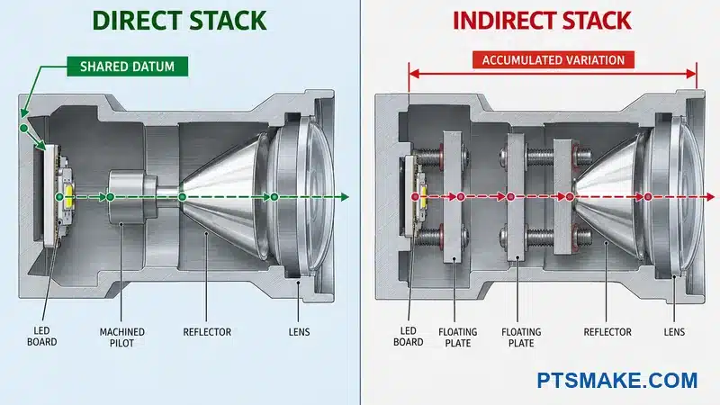
| Optical condition | Stronger mechanical control | Weaker control |
|---|---|---|
| LED radial position | Pins or locating edges tied to the optical datum | Board outline floating in wide screw holes |
| Optic radial position | Dedicated pilot or seat from the same datum | Cosmetic shell diameter |
| Focal height | Direct shoulder and a short rigid stack | Several soft or unfinished layers |
| Rotation | Key, tab, or asymmetric locating pattern | Installer judgment |
| Lens relation | Controlled seat tied to the optical frame | Cover position through loose fasteners |
The product team’s method should control whether the stack uses worst-case or statistical calculation. One very tight housing dimension should not hide all variation. Purchased optics, boards, seals, and retainers also contribute. The team needs current supplier tolerances before it assigns the housing allowance.
Provide assembly error-proofing
The design should make a wrong orientation difficult. An asymmetric pin pattern, keyed carrier, visible clocking feature, or connector clearance can help. The assembly process should also show how the optic seats and how the technician confirms full engagement.
The assembly path should keep tools away from the LED and reflective surfaces. A driver path that crosses the optic can lead to scratches or contamination. A retaining ring needs a usable tool interface. If adhesive is required, the housing needs a controlled bond area and a path that keeps excess material away from the optical aperture.
Verify the assembled beam
Dimensional inspection can confirm the machined relationships, but it cannot prove the final beam by itself. I link the datum and tolerance plan to an assembly and optical test. If the beam fails, the team can then separate housing error, component variation, assembly error, and test setup error.
This traceable loop is more useful than tightening every concentric diameter. It lets us spend CNC precision on the features that actually control the optical stack.
Open Internal Cavities to Real Tools and Real Cleaning
Design for a cutter with finite length and diameter
A CAD pocket can be easy to draw and hard to machine. Deep narrow cavities need long tools. Long tools bend more, vibrate more, and often need lighter cuts. A small internal radius can force a small cutter through an entire pocket even when most of the material could use a larger tool.
The cavity review should identify which surfaces truly need the deepest wall and smallest radius. The entry can open, the wall can shorten, or the corner radius can grow when function allows it. If a mating insert has a sharp outside corner, a local relief is often better than a sharp internal corner throughout the cavity.
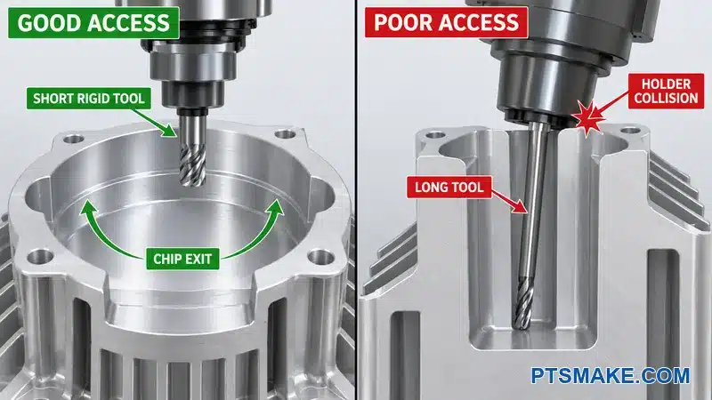
At PTSMAKE, our five-axis CNC machining capability can improve access to angled faces and radial features. It does not remove cutter diameter, holder clearance, or chip evacuation limits. The design still needs physical access.
Review the tool, holder, and spindle path
Tool access extends beyond the cutting edge. The tool holder and spindle nose also need clearance. A tapered outer wall or tall boss can block the holder before the tool reaches the floor. An angled approach can help, but it may change the datum and workholding plan.
The review should also check how the tool leaves the cut. A narrow slot with no overtravel can create dwell marks or force a special tool. A thread near a shoulder may need a relief. A sealing face may need space for a cutter to enter and exit without leaving a step across the gasket path.
| Geometry | Common process effect | Practical design response |
|---|---|---|
| Deep narrow pocket | Long tool, lower stiffness, slower removal | Open the entry or reduce depth where function allows |
| Small internal radius | Small cutter controls the whole operation | Increase the radius or localize the small feature |
| Tall boss near a wall | Holder collision and poor chip flow | Add clearance or change the approach |
| Closed annular groove | Difficult chip removal and inspection | Add access and define the functional segment |
| Sharp insert corner | Impossible milled internal corner | Use corner relief or change the insert |
Create a path for chips and cleaning media
The cavity must release chips during cutting. It must also release wash fluid after machining. Chips can hide behind ribs, in blind threads, under ledges, and between close fins. A part that looks clean from the opening can retain debris near the LED or optic.
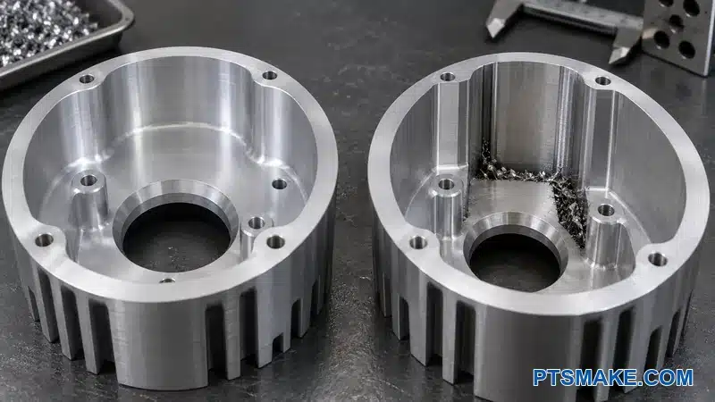
The housing needs review in likely machining and wash orientations. Gravity matters. Blind upward pockets can hold fluid. Narrow gaps can resist rinsing and drying. If the product needs special optical or electronic cleanliness, the requirement should define the accepted condition and verification method.
Plan deburring before release
Cross holes, interrupted threads, fin roots, and internal slots can create hard-to-reach burrs. A vague “break all edges” note does not explain which edges touch a seal, wire, board, or technician. I mark critical edge conditions and allow a practical method.
The team should decide whether media blasting, tumbling, brushing, hand deburring, or thermal methods are acceptable. Each process can change appearance or functional edges. The plan must also account for cleaning after deburring.
Use access as a cost and quality lever
Better access often reduces tool count, cycle time, burr risk, and cleaning effort at the same time. I treat an open cavity as more than a machining convenience. It can make inspection and assembly more reliable.
Product function still sets the boundary. A wall that carries heat, seal load, shielding, or structural load should not open without review. The right change keeps the interface and removes unnecessary obstruction.
Balance Walls, Fins, Ribs, and Bosses for Rigidity
Make thin features support process loads
Thin fins can add surface area and reduce weight. They can also vibrate during cutting, bend during handling, and show finish variation. Tall bosses can move when the surrounding floor is thin. I review height, thickness, spacing, cutter direction, and clamp load together.
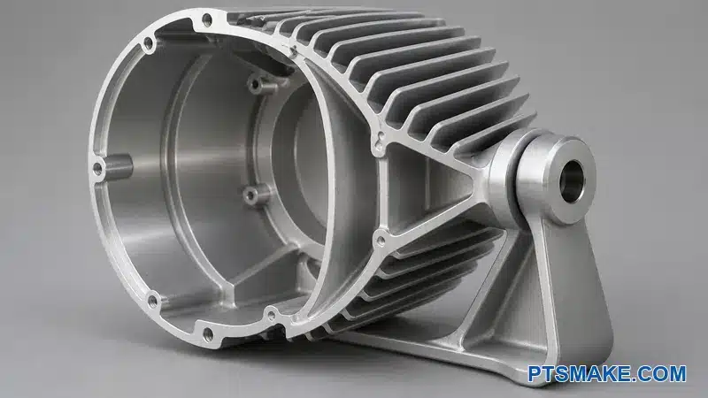
Gradual section changes usually behave better. A loaded pivot boss needs a broad load path into the body. Ribs should support a known load. A decorative rib can block a larger cutter and add deburring work without improving function.
Leave a stable finish-machining condition
Roughing can release material stress and heat. A broad land or thin optical ring may move after the main cavity is opened. The process may need staged roughing and finishing, but the part must still have a stable place to locate and clamp.
One universal minimum wall or fin thickness would be misleading. The workable value depends on alloy, unsupported height, tool, tolerance, surface finish, quantity, and fixture support. The shop should flag the features that need special support or a slower process.
Review boss loads locally
A pivot boss can see clamp load, aiming torque, impact, and repeated adjustment. The bulk housing alloy does not prove that the local shape is adequate. The product engineer should check the load case, fillet, edge distance, wall connection, and mating bracket.
The CNC review then checks tool access and distortion. A thick isolated boss beside a thin wall can create uneven stock removal. A deep pivot bore may need support from both sides. A cross bolt also needs room for its head, nut, washer, and tools.
| Feature | Product role | Manufacturing question |
|---|---|---|
| External fins | Reject heat to ambient air | Can the cutter reach the roots without weak blades? |
| Main wall | Carry heat and structural load | Will roughing or clamping distort the wall? |
| Rib | Stiffen a known load path | Does it help more than it blocks access? |
| Pivot boss | Carry aiming and locking loads | Is the boss supported and machinable from a stable datum? |
| Screw boss | Transfer clamp load | Is there enough seat area and driver clearance? |
Thermal and structural work must stay connected. Removing metal may reduce cycle time but also narrow the heat path. Adding fins may improve area but make cleaning or coating harder. The final geometry should satisfy the validated product model and a stable machining process.
Reduce Setups Without Losing Datum Control
Count controlled orientations
Each new orientation adds handling, probing, workholding, and another datum transfer. Five-axis machining can expose more faces in one hold. Four-axis indexing can repeat radial features. A simple part may still run best in two clear three-axis setups.
The setup review counts the orientations needed to reach functional features. Related features should stay together where the fixture and tool allow it. The optical pilot, LED land, and nearby locating features often benefit from one controlled operation because their relationship matters more than their relation to a cosmetic shell.
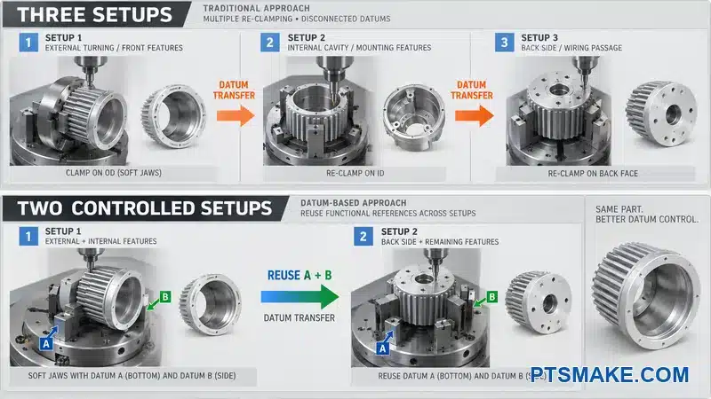
Give the fixture a real grip zone
Designers often use every outside surface for appearance. The shop then has no stable place for jaws, stops, or clamps. I reserve a clamp band, stock extension, sacrificial pad, removable tab, or existing noncosmetic surface when the part needs one.
The fixture should resist cutting force without bending the housing. A thin ring can become round only after the jaws release it. A broad face can look flat only while the clamp holds it down. I ask how the part will behave in the free state because inspection and assembly usually happen after release.
Protect the datum through each operation
The first setup creates features that locate the next setup. Those features need enough size, stiffness, and access. If anodizing occurs before a later operation, the finish can change or damage the location. If all machining occurs before finishing, the process must account for coating on the final fit.
| Setup question | Why it matters | Possible response |
|---|---|---|
| Where does the first operation grip? | The blank must resist roughing forces | Leave stock or a clear clamp band |
| Which features stay in one hold? | Shared machining reduces transfer error | Group related optical and thermal features |
| What locates the second operation? | Weak transfer features add variation | Create stable pads, pilots, or jaws |
| How is the finished surface protected? | Re-clamping can mark cosmetics | Use protected contact zones and clean fixtures |
| What does inspection recreate? | A different datum can hide process error | Use the same functional frame |
Setup count is not a useful goal by itself. One crowded setup can use long tools, poor approach angles, or weak clamps. Two robust setups can be safer. The best plan reduces unnecessary transfers while keeping each operation stable.
Use in-process inspection at the right point
Some features are easiest to check before the part leaves the fixture. A probe can verify stock position or a critical bore during machining. That check does not replace final inspection, but it can catch a setup issue before more value is added.
The supplier should show which controls happen in process and which happen after finish. This split matters for coated fits, sealing faces, and cosmetic zones. It also helps the customer understand what the quoted inspection scope includes.
Changeover needs also belong in the fixture review. A fixture should make wrong loading difficult, and its contact points should be easy to clean. These details protect repeatability when operators load many parts.
An illustrative two-setup review
Consider a 6061-T6 housing for a 60 W outdoor spotlight and a planned pilot batch of 120 pieces. The model uses a front optical bore, a rear LED land, two side pivot bores, and a clocking notch. The first process concept places those features across three orientations. That plan forces the optical axis to move through two datum transfers before final inspection.
In this example, the rear land becomes datum A, the optical bore becomes datum B, and the notch becomes datum C. The design also adds a 6 mm-wide grip band outside the sealing path. A first operation creates A and B from round stock. A second soft-jaw operation locates from those finished features and machines the pivot bores, cable port, and notch. This proposed route removes one transfer without forcing a long tool into the front cavity.
The expected benefit is a simpler datum chain and one fewer handling step. It is not a claimed production result. A supplier would still need to confirm tool access, clamp force, stock condition, cycle time, and inspection repeatability from the released files.
| Example control | Planning value | Reason for the value |
|---|---|---|
| Primary reference | Rear LED land as datum A | It supports the board and creates the main assembly plane |
| Optical reference | Front pilot bore as datum B | It controls the beam axis from the functional seat |
| Clocking reference | Cable-side notch as datum C | It fixes rotation for the bracket and cable path |
| Pilot quantity | 120 pieces | It can justify repeatable soft jaws without assuming high-volume tooling |
| Inspection record | Sample layout with actual results left blank | It defines the method without pretending that parts have been measured |
Let production quantity guide the fixture
Prototype fixtures should support learning and reasonable changes. Production fixtures should support repeat loading, chip control, tool access, and part protection. A dedicated gauge may make sense when it checks a repeated functional relationship faster than a full CMM routine.
At PTSMAKE, we choose among three-axis, four-axis, five-axis, turning, and mill-turn routes after we review the part and expected quantity. The process name comes after the datum and workholding logic. This order gives the customer a clearer reason for the proposed route.
Design Holes, Threads, Pivots, and Fastener Access Together
Design the complete connection
A threaded hole is only one part of a connection. I review the fastener, engagement, counterbore, seat, driver path, mating part, edge distance, and service method together. A correct thread can still be unusable when a fin blocks the tool or the screw head sits on a curved surface.
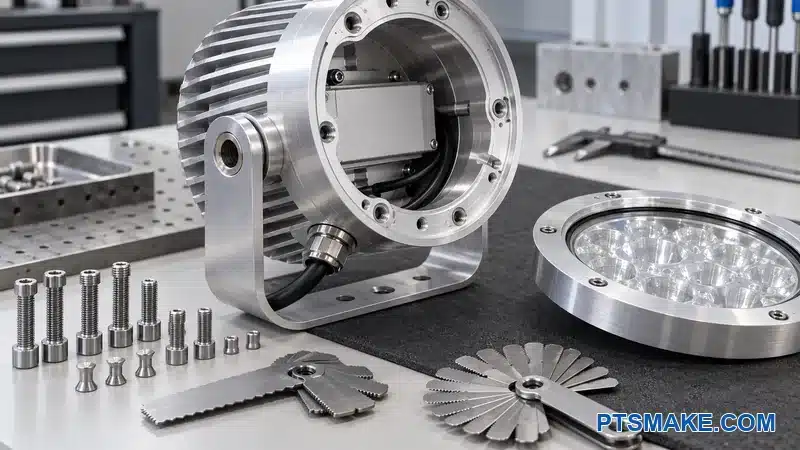
Standard thread forms and available fasteners are usually the safest starting point unless the product needs something special. The drawing should identify whether a thread is cut before or after finishing. It should also define any required mask, insert, thread lock, sealant, or conductive contact area.
Leave room at blind ends
A blind threaded hole needs space for the drill point, tap lead, chips, and the fastener end. I do not place full thread depth against a physical bottom without checking the tool. I also keep deep small threads away from thin walls when the layout allows it.
For a cable gland or sealed plug, I review the thread and its sealing face as one interface. The thread may pull the component in while a shoulder, gasket, or tapered form creates the seal. The assembly torque and supplier specification matter more than a generic hole note.
Treat the pivot as a functional joint
The pivot bore, bracket, bolt, washer, and locking feature control aim. I ask whether the joint rotates on the bolt, a bushing, or a machined shoulder. I also ask how the user locks it and how many adjustments the product expects.
| Connection feature | DFM check |
|---|---|
| Threaded hole | Tool depth, engagement, edge distance, finish, and gauge access |
| Counterbore | Head seating, corner radius, driver clearance, and chip removal |
| Pivot bore | Fit, axis relation, bearing area, and inspection access |
| Cable port | Thread standard, seal surface, wrench clearance, and strain relief |
| Ground point | Bare contact area, corrosion plan, and assembly control |
Special threads need clear marks, and similar systems should not mix without a reason. The geometry also needs room for a go/no-go gauge where thread inspection is required. A feature that cannot be reached by a driver, wrench, or gauge is not fully designed.
Design Sealing Features Around Compression and Test Access
Start with the complete sealing stack
The sealing review covers the housing, lens, gasket or O-ring, groove, fasteners, finish, and pressure path together. The groove alone does not create a seal. The mating part must stay stiff enough, the fasteners must create even load, and the assembled product needs a way to verify leakage.
The Parker O-Ring Handbook8 explains that gland design depends on seal type, motion, pressure, material, and application conditions. I use the selected seal supplier’s data for the actual gland. I do not copy a groove from a different diameter or application.
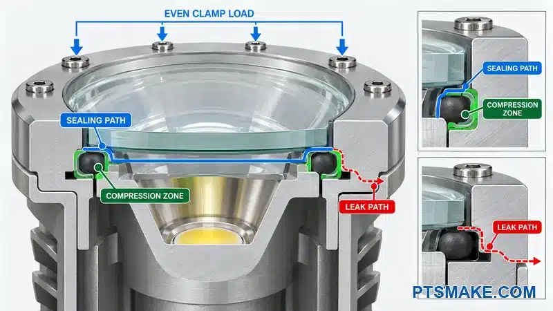
Maintain continuous compression
The groove should follow a continuous path without abrupt section changes. The surrounding flange needs enough width and stiffness. Fasteners should create even compression instead of pulling only at a few points. A corner or cable feature should not interrupt the sealing land unless the seal system is designed for it.
The groove and mating face should come from functional datums. Surface texture and tool marks also need review. A scratch or burr that crosses the sealing direction can create a leak path. A finish change near the groove can change dimensions or damage the seal during assembly.
The seal should not carry the full lens location unless its compression behavior is part of the optical design. I prefer a hard stop or separate locating feature when the product needs stable focal height. The seal can then provide compression within its approved range while the housing controls position.
Plan fastener load and flange stiffness
More fasteners do not automatically create a better seal. Their spacing, torque, seat stiffness, and assembly sequence matter. A thin flange can bow between screws. A very stiff lens can load the gasket differently from a flexible cover.
| Seal design item | Question to close before release |
|---|---|
| Seal material | Is it compatible with temperature, fluid, UV, and expected life? |
| Groove geometry | Does it match the selected seal and application type? |
| Mating surface | Is the texture, flatness, and edge condition defined? |
| Fastener pattern | Does it create even compression without flange distortion? |
| Finish | Which surfaces receive coating, masking, or post-finish machining? |
| Assembly | How does the operator avoid twist, pinch, contamination, or damage? |
| Test | What method, condition, fixture, and acceptance rule apply? |
Design test access into the product or fixture
IEC 605299 defines the IP classification system for protection against solid objects and water. An IP target is a product-level requirement. A machined housing by itself cannot prove that the complete luminaire meets the target.
The validation plan should state how the assembled unit will be tested. A pressure or vacuum test may need a temporary port, a sealed connector, or a fixture interface. A water test needs the defined orientation and exposure. The team should also decide whether every production unit, a sample, or only the design is tested.
The test method should not hide in vague notes. The controlled document should state the medium, pressure or exposure, duration, stabilization, temperature if relevant, and acceptance condition. Those values must come from the product validation plan. Machining DFM should not invent them.
An illustrative seal-stack review
Consider a front lens that sits on a face seal inside a black-anodized aluminum bezel. The first model controls groove depth from the cosmetic front surface, while the lens stop comes from an internal shoulder. Those two references can move independently after machining and finishing. The buyer may then face a frustrating problem: every separate dimension looks acceptable, but the assembled seal load remains hard to explain.
In this example, the revised drawing controls the groove and lens stop from the same functional flange. The finish map keeps the actual sealing track clear, while the visible bezel remains anodized. The fastener pattern stays symmetric around the optical axis. The inspection plan records groove geometry and flange flatness after the defined finishing stage. It leaves pressure, duration, and leak limits to the product validation specification.
This scenario does not claim a customer test or measured leak-rate improvement. It shows how a shared reference can remove ambiguity before a real enclosure test begins.
Protect seals during assembly
Sharp lead-in edges can cut an O-ring. A rough thread can drag a cable seal. Chips and blasting media can remain in a groove. I add a suitable lead-in, identify critical edges, and define cleaning. I also check whether the technician can see or feel that the seal is seated.
At PTSMAKE, we can machine and inspect the defined gland and mating features. We still need the chosen seal data and the customer’s enclosure test plan. This division keeps the manufacturing controls traceable to real product requirements.
Plan Anodizing and Coating Before Final Dimensions
Treat finish as part of the dimensional stack
Anodizing changes the surface and can affect fits, threads, electrical contact, thermal interfaces, seal lands, and cosmetic color. I place finish decisions before final tolerance decisions. I do not send a finished model to coating and then ask why the optic pilot or thread feels different.
The Aluminum Anodizers Council guide10 explains that anodizing forms an oxide layer from the aluminum surface. A complete specification also covers alloy, process, appearance, and function. The exact dimensional effect depends on the process and supplier. I ask the finishing source for its expected range on the selected alloy and geometry.

Mark coated, masked, and post-machined areas
The drawing should show which areas receive the finish. It should also show any mask boundaries. A thermal land may need bare metal. A grounding pad may need electrical contact. A precision pilot or thread may need a controlled finished size. Each choice has a corrosion, appearance, and process consequence.
A broad note that says “mask critical surfaces” is not enough. The finisher cannot know which surfaces the designer considers critical. The drawing should define the areas, boundary tolerance, acceptable rack location, and allowed touch-up if the product needs those controls.
Post-finish machining can restore a fit or electrical contact. It also exposes bare aluminum and creates a visible transition. The product team should approve that condition. Sometimes a designed mask is better. Sometimes the fit can accept the coating. The decision depends on function.
Separate dimensional and appearance controls
Color and gloss can vary with alloy, temper, stock surface, pretreatment, geometry, and batch conditions. A numerical color value can help, but a physical approved sample often gives the team a clearer visual reference. The sample must represent the intended alloy and finish route.
| Finish concern | Drawing or control-plan response |
|---|---|
| Precision fit | State whether the dimension applies before or after finish |
| Thermal contact | Define coating or masking on the contact land |
| Electrical ground | Define the bare conductive area and corrosion plan |
| Thread | Define finish condition, mask, chase, insert, and gauge stage |
| Seal land | Review growth, texture, edge condition, and finish damage |
| Cosmetic match | Use approved samples and viewing conditions |
| Rack mark | Define allowed hidden zones when appearance matters |
The PTSMAKE guide to anodizing aluminum alloys provides a broader process overview. In the housing drawing, I keep the instruction specific to the selected part and its interfaces.
Plan the inspection stage
A dimension can be checked before finish, after finish, or at both stages. The correct point depends on what the mating part sees. A final-fit diameter usually needs a finished-state requirement. A process control dimension may be useful before finish as well.
The control plan should name who owns each check and how the part is protected after inspection. A clean bare thermal land can be damaged by later handling. A finished cosmetic shell can be marked by a metal fixture. Soft contact materials, clean packaging, and controlled loading become part of the production plan.
Keep finish language verifiable
Terms such as “premium black” or “perfect finish” are not measurable. I define alloy, process designation, color reference, gloss or texture when needed, cosmetic zones, viewing conditions, and allowed defects. I keep those requirements proportional to the product.
PTSMAKE can coordinate CNC machining and the specified finish route, but the customer should approve appearance samples before volume production. The sample approval gives both teams a real reference and reduces subjective disputes.
The approved coupon should stay with its alloy, temper, pretreatment, color, gloss, and date. A loose sample without this record cannot guide a later batch.
Mark Cosmetic Zones, Edge Rules, and Cleanliness Needs
Divide surfaces by visibility and contact
The drawing should mark primary cosmetic faces, secondary visible faces, hidden faces, and functional contact areas. The same scratch limit should not apply to a front bezel and an internal roughing pocket. A zone map lets the shop protect the important faces without adding unnecessary handling to every surface.
The map should include allowed rack or clamp zones. It should also identify faces that touch seals, wires, hands, boards, or optics. Those faces may need edge or cleanliness controls even when the customer cannot see them.
Replace vague edge notes with functional rules
“Deburr all edges” leaves room for different results. I identify sealing edges, wire passages, assembly lead-ins, exposed user edges, and edges that must remain sharp for location. I then define the required condition or an approved range where needed.
A large break on an optic seat can change axial contact. A small burr in a wire path can cut insulation. A rounded cosmetic edge can help finish consistency. These edges need different instructions.
| Zone | Main concern | Useful control |
|---|---|---|
| Front bezel | Visible scratches and color variation | Approved sample and protected handling |
| Seal land | Cross scratches, burrs, and contamination | Functional texture and edge definition |
| Cable path | Sharp edges and trapped chips | Edge condition and cleanliness check |
| Thermal land | Burrs, coating, debris, and dents | Defined contact zone and protective packaging |
| Hidden cavity | Loose chips or wash residue | Cleaning and visual acceptance method |
Define cleanliness from the next process
Optics, electronics, adhesive, potting, and thermal interfaces have different contamination risks. I ask what happens after machining. The answer guides washing, drying, gloves, packaging, and inspection.
A claim such as “particle free” needs a real standard and test method. A practical note can define no visible chips, no loose media, and a named inspection condition. Higher cleanliness needs require a controlled specification, environment, and verification method.
Trapped water also deserves attention. Deep blind holes and narrow channels can hold wash fluid. The design can add drainage, open access, or a different orientation. Good cavity DFM often improves both cutting and final cleanliness.
The packaging plan should preserve that cleanliness until assembly.
Apply Tolerances, GD&T, and Surface Finish Only to Function
Start with the failure and the mating part
The tolerance review should not begin with the tightest value that a machine can sometimes hold. It should begin with the failure map and the mating component. The tolerance must protect optical alignment, thermal contact, sealing, mounting, or assembly. A tight dimension without a stated functional effect deserves a challenge.
PTSMAKE can achieve tolerances as tight as ±0.005 mm on suitable features. That capability is conditional. Material, geometry, feature size, setup, inspection, surface treatment, and quantity all affect feasibility. A capability statement should not become a blanket tolerance across a housing.
Use geometric controls for relationships
Size tolerances cannot fully control orientation, location, or form. A bore can meet its diameter and still point in the wrong direction. A flange can meet thickness and still be warped. GD&T lets the drawing control these relationships from a functional datum frame.
Flatness can control one surface’s form. Perpendicularity or parallelism can control orientation. Position or run-out can relate an axis or pattern to the datum system. Profile can set a controlled boundary for a complex surface. The exact control must match the assembly and inspection plan.
ASME Y14.5 and ISO 1101 use related concepts but are not interchangeable line by line. I state one governing system and edition. I do not mix symbol conventions from different standards without review.
Build a tolerance budget
The product-level allowance needs distribution across each contributor. The housing, LED board, optic, lens, gasket, bracket, and assembly method can all add variation. If the total is too large, the first response should shorten the chain or improve location. One CNC feature should not carry the full correction by default.
| Function | Likely contributors | Better question |
|---|---|---|
| Beam center | LED location, optic seat, board location, assembly | Which features directly control the optical centers? |
| Focal height | Housing shoulder, board, optic, gasket, retainer | Can the stack use fewer hard dimensions? |
| Seal compression | Groove, seal section, lens, flange, fastener load | Which stops control compression and flatness? |
| Pivot aim | Bore location, bracket, bolt or bushing, clamp load | Which axis must relate to the optical axis? |
| Cover fit | Pilots, coating, fastener clearance, flange form | Is the final state measured after finish? |
The calculation should state whether it uses worst-case limits or a statistical method. The choice should match the production and quality plan. A statistical assumption without process data can create false confidence.
Specify surface finish where it changes function
Surface roughness can affect thermal contact, sealing, bearing, sliding, appearance, and coating. It does not need to be equally fine everywhere. A broad, unnecessary fine finish can add passes and inspection without improving the product.
The drawing should mark the contact zone and the measurement direction or method when it matters. A sealing face also needs review for tool marks that cross the seal. An optic seat may care more about form and location than a very low roughness number.
Make every control inspectable
Each critical requirement needs a practical measurement method. A deep bore may block a probe. A thin flexible wall may change under contact force. A cosmetic surface may need noncontact inspection. A thread or seal groove may need a special gauge.
The drawing should provide accessible datum targets and enough feature length for the method. It should also identify whether the requirement applies before or after anodizing. When a tight value requires a special fixture or full CMM report, the request for quote should say so.
Use a review loop instead of blanket precision
The customer should mark critical-to-function features. We then compare the tolerances with the proposed machine, setup, finishing route, and inspection. If a control adds high cost, we explain the reason and offer a functional alternative when possible.
This review does not weaken the design. It makes the precision traceable. The drawing becomes easier to quote, make, inspect, and revise because each tight control has a reason.
Reduce Cost Without Weakening Critical Requirements
Remove cost from noncritical work
Cost reduction should start with the process drivers. Excess stock removal, deep pockets, small corner radii, long tools, extra setups, special threads, broad fine finishes, and low-value inspection deserve the first review. A critical optical or sealing control should not be the first target.
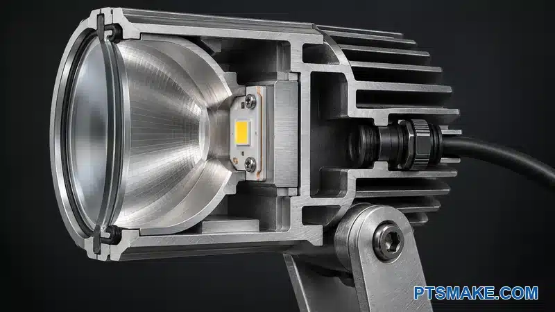
The interface map gives us a safe boundary. We protect the LED land, optical stack, seal, pivot relationship, and mounting interfaces. We then simplify material around areas with low consequence. This method turns cost reduction into an engineering review instead of a general request to make the part cheaper.
Compare total process cost
A lighter housing does not always cost less. Thin walls can need slower cutting and gentler clamping. A larger internal radius can add a small amount of material but allow a stronger tool. A split body can reduce pocket depth but add assembly and sealing work.
| Cost driver | Possible review action | Function to protect |
|---|---|---|
| Large billet and heavy roughing | Compare tube, extrusion, or revised envelope | Heat path and structural margin |
| Deep narrow cavity | Open access or split the body | Sealing and assembly needs |
| Small internal radii | Increase radius or localize relief | Mating component clearance |
| Extra orientation | Align features or revise access | Datum relationships |
| Fine finish across all faces | Limit it to functional zones | Contact and appearance requirements |
| Full inspection of flexible features | Use risk-based sampling or a functional gauge | Customer quality plan |
Repeat volume should guide any fixture or gauge recommendation. A dedicated solution can reduce production cost, but it may not make sense for a changing prototype. The quote should separate one-time tooling from part cost when that difference helps the customer decide.
Allow controlled supplier proposals
A useful drawing protects requirements and leaves noncritical process details open. The request can ask the supplier to propose stock form, setup grouping, standard cutter radii, or inspection method. The customer can then approve the proposal without giving up design control.
At PTSMAKE, we explain a cost-down suggestion in terms of geometry, process, and the protected interface. We do not promise a fixed saving before we review the model, quantity, material, finish, and inspection scope. That approach keeps the recommendation factual.
Include Assembly, Service, and Certification in the Housing Design
Walk through the assembly sequence
The assembly review follows the order for the LED board, wires, optic, lens, seal, cover, bracket, and cable gland. It checks whether tools can reach each fastener without touching an optic or pinching a wire. It also checks whether the housing provides clear locating feedback.
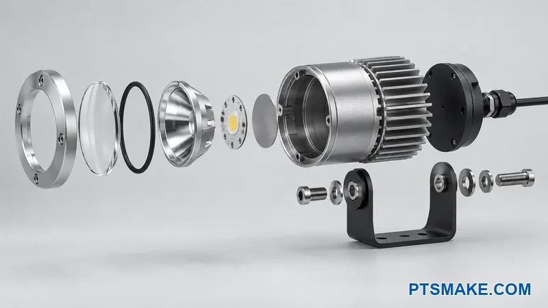
An asymmetric pin pattern or keyed carrier can prevent a wrong orientation. A lead-in can help a seal enter without damage. A wire channel can keep the cable away from the lens seat and screw path. These small features can prevent assembly variation more effectively than a tighter general tolerance.
Design realistic service access
If the product needs LED, driver, lens, or seal replacement, the technician needs access after installation and aging. I ask which fasteners remain reachable, which seals need replacement, and which finish surfaces can tolerate tools. A permanent adhesive or hidden ring may conflict with the service plan.
Repeated opening can also affect threads in aluminum. A steel insert may help some designs, but it adds material, installation, and corrosion questions. The product load and service frequency should guide that choice.
Connect certification needs to controlled features
Certification applies to the finished product and its documented construction. The UL lighting industry guidance11 describes lighting evaluation across electrical, mechanical, thermal, environmental, and related safety considerations. The target market and applicable standard should come from the product compliance owner.
The housing can affect grounding, wire protection, flame barriers, spacing, ingress protection, and temperature. I ask the compliance team to identify controlled construction details before the design freezes. I do not label a housing as certified because PTSMAKE holds ISO 9001 certification or because the metal part meets its drawing.
The drawing and bill of materials should preserve the features and materials that the certification plan controls. A supplier change that looks harmless can affect the approved construction, so the change process needs a clear owner.
The inspection plan should also mark safety-related characteristics when the compliance owner requires them. This step keeps a later drawing change from bypassing the required review.
Validate the Prototype and First Production Batch
Use the prototype to close named risks
The interface map should lead to a validation matrix. A prototype should answer optical, thermal, sealing, mounting, assembly, finish, and service questions. A dimensional report alone does not close every risk.
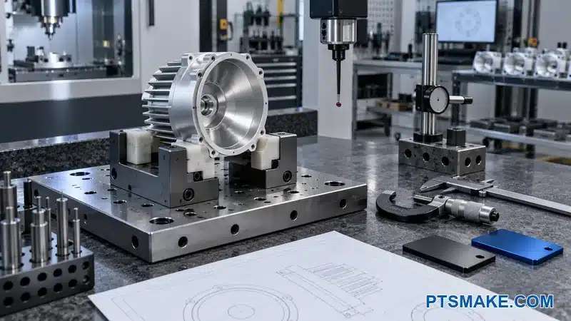
The team should record the part revision, material lot, finish route, component revisions, assembly method, and test setup. This traceability helps when a later result changes. It also stops the team from approving a geometry with one component and producing it with another.
Separate design validation from process validation
Design validation asks whether the assembled spotlight meets its product requirements. Process validation asks whether the planned manufacturing route can repeat the defined characteristics. The two activities support each other, but they do not use the same evidence.
| Validation area | Example evidence owner |
|---|---|
| Optical output and beam alignment | Product optical team |
| Temperature under defined load | Product thermal team |
| Ingress or leak performance | Product validation team |
| Material, dimensions, and GD&T | Supplier and customer quality teams |
| Finish color and cosmetic condition | Approved visual standard and inspection |
| Assembly time and error-proofing | Manufacturing engineering |
First-article inspection compares the manufactured part with the controlled drawing. The team should then review actual assembly feedback. A dimension can meet its limit and still create difficult assembly if the stack or method was incomplete.
Control the first production batch
The first batch should use the intended material, tools, fixture, finish source, inspection plan, and packaging where practical. I watch the features that had the highest interface risk and the features that needed process learning.
The team should define reaction rules before the batch begins. If a feature trends toward a limit, the supplier and customer need a clear review path. I do not invent a sample size or capability threshold because those values depend on the customer’s quality plan and product risk.
At PTSMAKE, we can provide the agreed dimensional and process records for the machining scope. The customer combines those records with assembly and product test evidence to approve production.
Share your CAD and inspection requirements for a practical manufacturing review.
Build a Quote-Ready DFM Package
Send a controlled model and drawing together
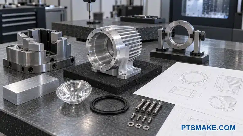
A reliable quote needs more than a STEP file. The 3D model defines the shape, but the drawing defines datums, tolerances, finish, threads, critical interfaces, and inspection expectations. Both files need matching revision control.
The quote package should include the selected LED, optic, lens, seal, bracket, fasteners, and cable components when their geometry controls the housing. Supplier drawings or models are useful. A screenshot without a part number or revision is weak evidence.
Include the commercial assumptions that change the process
Quantity affects stock, fixtures, inspection, and programming. The request should show prototype quantity, expected production batch, forecast when available, target date, delivery location, and packaging needs. The supplier should not guess whether a one-piece quote is a one-time prototype or the first step toward recurring production.
The request should state the alloy, temper, finish, color, and certification documents. It should also state whether the quote includes material certificates, first-article inspection, full reports, finish samples, leak-test support, or special packaging. These items can change both cost and lead time.
Use a clear quote checklist
| Package item | What I expect |
|---|---|
| 3D CAD | Native or neutral solid model with a revision |
| 2D drawing | Functional datums, tolerances, GD&T, threads, finish, and notes |
| Component data | Current files for the LED, optic, lens, seal, bracket, and connectors |
| Material | Alloy, temper, accepted specification, and certificate needs |
| Finish | Process, color reference, masked zones, cosmetic zones, and sample plan |
| Inspection | Critical features, report scope, standards, and finished-state requirements |
| Validation | Assembly, optical, thermal, seal, and first-batch responsibilities |
| Commercial scope | Quantities, delivery, schedule, packaging, and expected repeat demand |
Open questions should stay visible. A supplier can quote a controlled assumption when the missing item has a limited effect. If the missing item changes the architecture, seal, alloy, or critical tolerance, the team should close it before a firm production quote.
Ask for DFM feedback in a structured form
The supplier should list the feature, issue, reason, proposed change, expected effect, and required customer decision. This format is easier to review than scattered screenshots. It also creates a record for later drawing revisions.
The supplier should separate a hard manufacturability issue from a cost or risk suggestion. A feature may be possible but expensive. Another feature may be impossible with the stated tool access. The customer needs that distinction to make a sound decision.
Define acceptance before the purchase order
The final package should state which revision controls, which standards apply, and which evidence closes acceptance. It should also define how approved deviations are recorded. Email approval can be lost if it never reaches the drawing or purchase order.
For machined aluminum spotlight housings, I pay special attention to the finished-state optical seats, LED land, seal gland, pivot relationship, thread condition, and cosmetic zones. Those interfaces often cross machining, finishing, assembly, and product testing.
PTSMAKE has provided custom machining services since 2002 under PTS Industrial Ltd. Our scope includes three-axis, four-axis, five-axis milling, CNC turning, and mill-turn machining. We can review tight features down to ±0.005 mm where the material, geometry, setup, process, and drawing support them. We confirm that feasibility during drawing review rather than applying the value to every feature.
Keep one decision log
A short decision log closes the quote package. It records accepted DFM changes, open product decisions, approved finish samples, and the inspection scope. The log does not replace the drawing. It helps the team make sure that approved decisions reach the controlled files.
When the model, drawing, component data, finish requirements, inspection scope, and quantity agree, the supplier can quote a real process. The customer also receives a clearer basis for comparing proposals beyond the lowest unit price.
Send Us Your Spotlight Housing for a Practical DFM Review
Send us your CAD model, drawing, quantity, finish, and known optical, thermal, and sealing requirements. I will help our PTSMAKE team review the machining route and prepare a clear quote.

I cite this guide because it explains why LED luminaire life depends on thermal, optical, electrical, mechanical, and environmental system factors. It supports treating the housing as part of a complete luminaire. ↩
I cite this PTSMAKE comparison because it expands the process-selection question. It lets this guide stay focused on DFM after the team selects CNC machining. ↩
I cite this standards overview because it identifies the industry’s alloy and temper designation systems. It supports asking teams to specify more than the word “aluminum.” ↩
I cite this standard because it is the authoritative source for the GD&T system used in this article. It also identifies the governing edition. ↩
I cite this standard because it defines the international geometrical specification language for form, orientation, location, and run-out. ↩
I cite this white paper because it explains LED thermal resistance paths and interfaces. It supports the complete-path method instead of a housing-only heat-sink assumption. ↩
I cite this guide because it tells designers to align the LED optical center with the lens. It supports the review of mechanical and optical centers. ↩
I cite this handbook because it gives application and gland-design guidance. It supports using seal-specific data instead of treating one groove as a universal rule. ↩
I cite this standard because it defines the IP classification system. It helps separate product-level enclosure testing from dimensional inspection of the housing alone. ↩
I cite this guide because it covers alloy, process, appearance, and specification factors for anodized aluminum. It supports including finish in the dimensional and cosmetic plan. ↩
I cite this guidance because it covers electrical, mechanical, thermal, environmental, and related lighting safety considerations. It supports getting compliance inputs from the finished-product certification plan. ↩