Manufacturing engineers face a critical challenge: achieving consistent, high-strength metal joints without heat damage or material distortion. Traditional welding methods often introduce thermal stress, oxidation, and warpage that can compromise precision components.
Ultrasonic metal welding offers a solid-state joining process that creates molecular bonds through high-frequency vibrations and pressure, eliminating heat-affected zones while maintaining material properties and dimensional accuracy.
After working with various metal joining challenges at PTSMAKE, I’ve seen how the right ultrasonic welding approach can solve complex assembly problems. This guide covers 12 essential aspects that determine welding success, from material compatibility to process optimization strategies that ensure reliable production results.
What physical limitations define a material’s ‘weldability’?
Not all metals are easy to weld. A material’s "weldability" isn’t a simple yes or no. It depends on its core physical properties.
These properties dictate how a material responds to the welding process. For techniques like ultrasonic metal welding, this is crucial. Understanding them is key to success.
Key Factors in Weldability
Certain properties are more important than others. Hardness, ductility, and conductivity play huge roles. Material thickness also sets clear limits.
| Property | Impact on Ultrasonic Welding |
|---|---|
| Hardness | Too hard prevents plastic deformation |
| Ductility | Allows material to flow and bond |
| Conductivity | High conductivity dissipates energy |
| Thickness | Limits vibration energy transmission |
These factors together determine if a strong, reliable weld is even possible.
The Physics Behind the Limitations
The success of ultrasonic welding hinges on physics. The process uses high-frequency vibrations to create a solid-state bond. It doesn’t melt the metal. Instead, it uses friction and pressure.
Hardness and Ductility
Hardness is critical. If a metal is too hard, the vibrations can’t create enough friction or plastic deformation at the joint. The surfaces won’t bond. Conversely, good ductility allows the materials to flow and mix under pressure, forming a strong weld. Softer, more ductile metals are generally better candidates.
Conductivity’s Dual Role
Thermal and electrical conductivity also matter. Highly conductive materials like copper can be tricky. They dissipate the vibrational energy as heat too quickly. This prevents temperatures from rising enough at the weld interface to soften the material.
Thickness Constraints
Material thickness is a major physical barrier. The ultrasonic vibrations must travel through the top piece to reach the joint. Thicker materials dampen this energy. This reduces the effectiveness of the weld, making it difficult to achieve a solid bond. This entire process relies on creating sufficient interfacial slip1 between the surfaces.
A material’s suitability for ultrasonic welding is defined by its physical makeup. Hardness, ductility, conductivity, and thickness are not just abstract properties. They directly control whether a strong, solid-state bond can be formed by limiting energy transfer and material deformation at the weld interface.
What are the main categories of ultrasonic metal welding applications?
Ultrasonic metal welding is a versatile technology. Its applications are quite diverse. Each type requires a specific approach and expertise.
Let’s break down the main categories. We see it used across many industries. This ranges from automotive to medical devices. The process is adapted for different materials and shapes.
Here is a quick overview of common applications:
| Application Category | Primary Industry | Common Materials |
|---|---|---|
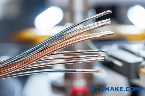
| Wire Splicing | Automotive, Electronics | Copper, Aluminum |
| Tube Sealing | Medical, HVAC | Copper, Aluminum |
| Battery Welding | EV, Consumer Electronics | Copper, Nickel, Aluminum |
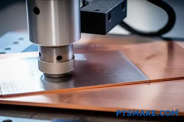
| Foil/Sheet Joining | Packaging, Solar | Aluminum, Copper |
Understanding these categories is key. It helps in selecting the right process for your project.
Navigating Application-Specific Challenges
Each category of ultrasonic metal welding presents unique hurdles. Success depends on understanding these complexities. It’s not just about applying pressure and vibration. It requires deep process knowledge.
Wire Splicing Complexities
Wire splicing might seem straightforward. But controlling the weld nugget is crucial. Too much energy can damage thin wires. Too little results in a weak, unreliable connection. The combination of materials also plays a big role here.
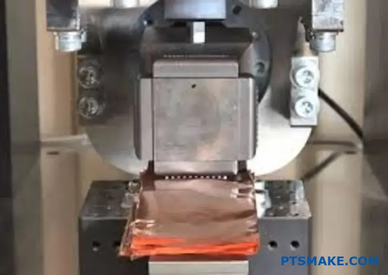
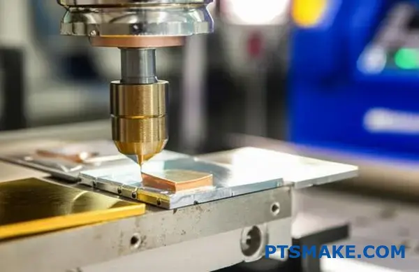
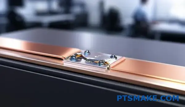
Battery Tab and Foil Welding
Battery manufacturing is a major area for this technology. Welding thin foils to tabs demands extreme precision. Any damage can compromise battery performance and safety. The main challenge is maintaining consistent weld quality. This must be done across thousands of parts. This process is very sensitive to surface contamination.
The high-frequency vibration induces a process called acoustic softening2. This makes the metal more pliable for a moment. It enables a solid-state bond without melting.
Challenges Overview
| Application | Key Challenge | Why It’s Difficult |
|---|---|---|
| Wire Splicing | Weld nugget control | Balancing joint strength and wire integrity. |
| Tube Sealing | Achieving a hermetic seal | Ensuring no leaks in critical systems like HVAC. |
| Battery Welding | Preventing foil damage | Thin materials are easily torn or overheated. |
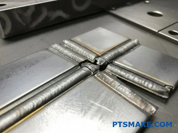
| Sheet Joining | Maintaining flatness | Large, thin surfaces can warp under pressure. |
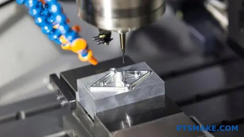
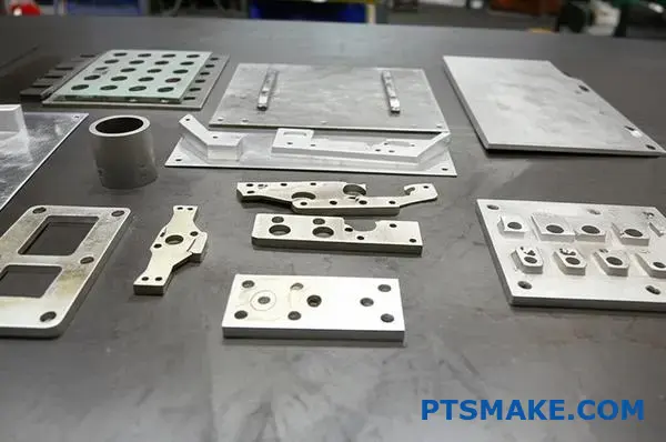
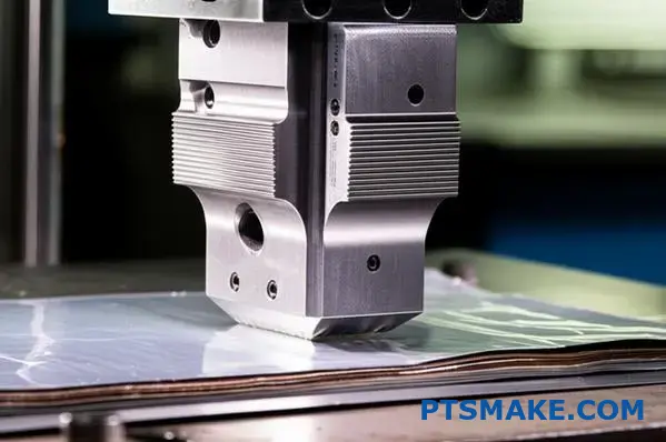
In past projects at PTSMAKE, we’ve machined components for welding fixtures. We understand how critical precision manufacturing is to support these advanced joining methods effectively.
Ultrasonic metal welding applications are highly specialized. From wire splicing to battery tab welding, each has distinct challenges. Success hinges on understanding these nuances and applying precise process control to achieve reliable, high-quality joints for every specific use case.
How do material combinations (e.g., Cu-Al) affect welding?
Welding dissimilar materials like copper and aluminum presents unique challenges. The core problem lies in their vastly different physical properties.
When you attempt to join them, they don’t simply fuse. They react chemically at the weld interface.
The Problem with Mixing Metals
This reaction creates brittle layers that can cause the weld to fail under stress. These layers are hard but lack toughness. They are the weak link in the chain.
Let’s look at their core differences.
| Property | Copper (Cu) | Aluminum (Al) |
|---|---|---|
| Melting Point | ~1083°C | ~660°C |
| Thermal Conductivity | High | Very High |
| Crystal Structure | FCC | FCC |
These conflicting properties make controlling the weld process absolutely critical for a successful joint.
Controlling Brittle Intermetallic Formation
When copper and aluminum are heated and mixed, they form various intermetallic compounds3. These compounds, such as Al₂Cu and Al₄Cu₉, are notoriously brittle and prone to cracking.
The thickness of this intermetallic layer is the enemy. A thicker layer results in a weaker joint. The primary goal is always to keep this layer as thin as possible, ideally just a few micrometers.
Fine-Tuning Welding Parameters
So, how do we achieve this? The answer is precise control over welding parameters. Heat input is the single most critical factor. Less heat means less reaction time and a thinner brittle layer.
This is where advanced processes like ultrasonic metal welding excel. They create a solid-state bond with minimal heat, bypassing many issues of fusion welding.
At PTSMAKE, we adjust multiple parameters for each unique application.
| Parameter | Adjustment | Impact on Cu-Al Weld |
|---|---|---|
| Heat Input | Minimize | Reduces intermetallic layer thickness |
| Welding Speed | Increase | Limits time for intermetallic growth |
| Pressure | Optimize | Ensures good atomic contact |
Based on our project experience, balancing these variables is key. It’s not about one setting, but the synergy between them. This is how we ensure a strong, durable, and reliable bond for our clients’ critical components.
Welding dissimilar metals like Cu-Al is difficult because of brittle intermetallics. The solution is precise parameter control, especially minimizing heat. This careful management limits the growth of these weak layers, ensuring a strong and reliable joint is formed.
What are the common failure modes in ultrasonic welds?
Recognizing weld failures is the first step toward process control. Each defect is a clue, pointing directly to a specific issue in your setup. It’s about diagnosing the symptoms to find the cure.
This prevents costly rejects and production delays. Let’s explore the most common failure modes you’ll encounter.
Under-Welding
This results in a weak bond that fails easily. The parts may seem joined but lack structural integrity. It’s a clear sign of insufficient energy reaching the weld interface.
Over-Welding
Here, too much energy is applied. This can cause cracks, material degradation, or flash (expulsion). It severely compromises the strength and appearance of the final assembly.
Material Sticking
When material melts and adheres to the horn, it’s a major problem. This defect damages the component’s surface and can halt production for tool cleaning.
Understanding what causes these defects is essential. In my experience, most issues trace back to a handful of key process parameters. By linking the failure mode to a parameter, you can make targeted adjustments. This systematic approach is far more effective than random guesswork.
The process relies on controlled Interfacial Friction4 to generate heat. When parameters are off, this friction is either too low or too high, leading to predictable defects. Challenges in ultrasonic metal welding often stem from getting this balance right.
Diagnosing the Root Cause
At PTSMAKE, we often help clients troubleshoot their welding processes. A logical diagnostic method is always the best path forward. Below is a table that links common defects to their likely causes.
| Weld Defect | Potential Parameter Issue | Common Correction |
|---|---|---|
| Under-Welding | Low Amplitude, Short Weld Time, Low Pressure | Gradually increase energy input parameters. |
| Over-Welding/Cracking | High Amplitude, Long Weld Time, High Pressure | Systematically reduce energy input. |
| Material Sticking | Excessive Heat, Poor Tool Finish, Wrong Material | Lower amplitude/time, check horn condition. |
| Inconsistent Peel | Parameter Fluctuation, Poor Part Fit-Up | Calibrate welder, improve part fixtures. |
This table serves as a solid starting point for troubleshooting. Always adjust one parameter at a time to isolate the variable causing the issue.
Recognizing these defects is crucial. Linking them to process parameters like pressure, time, and amplitude allows for precise troubleshooting. This ensures consistent, high-quality welds, saving valuable time and preventing material waste in your production line.
How does part cleanliness impact the welding process?
Surface contaminants are a significant obstacle to achieving a strong weld. Substances like oils, oxides, and drawing compounds form a barrier on the metal.
This barrier prevents the direct metal-to-metal contact required for a solid bond. The result is often an inconsistent and structurally weak weld joint.
Common Contaminants and Their Effects
| Contaminant | Primary Impact |
|---|---|
| Oils & Greases | Creates porosity, weakens the joint |
| Oxides (Rust) | Trapped as inclusions, causes brittleness |
| Drawing Compounds | Acts as a physical barrier, prevents fusion |
Therefore, proper cleaning is a critical, non-negotiable step in the welding workflow.
How Contaminants Disrupt the Weld
Contaminants actively interfere with the welding process. They introduce unwanted elements and prevent a true metallurgical bond from forming successfully.
The Problem with Oils and Greases
When heated during welding, oils and greases vaporize. This process releases gases, which can become trapped in the molten weld pool. This creates tiny bubbles, known as porosity, making the final weld weak and unreliable.
The Issue with Oxides
Oxides, such as rust, typically have a much higher melting point than the base metal. They don’t melt properly during welding. Instead, they get trapped as solid inclusions within the weld, reducing the joint’s strength and ductility.
The Barrier Effect
Ultimately, all contaminants form a dirty interfacial layer5 on the material’s surface. This barrier physically separates the metal parts. Some processes, like ultrasonic metal welding, depend on absolutely pristine surfaces to create a bond. This contaminated layer absorbs energy, disrupts heat flow, and prevents a proper fusion from occurring.
| Contaminant Type | Disruption Mechanism | Consequence |
|---|---|---|
| Organic (Oil) | Vaporization & Gas Formation | Porosity, Hydrogen Embrittlement |
| Inorganic (Oxide) | High Melting Point | Inclusions, Reduced Ductility |
| Processing (Compound) | Physical Barrier | Lack of Fusion, Poor Bonding |
In past projects at PTSMAKE, we’ve identified inadequate cleaning as the direct cause of component failure. It is a fundamental step for any reliable manufacturing process.
Contaminants like oils and oxides create a barrier preventing proper metal-to-metal bonding. This leads to weak welds with defects like porosity and inclusions. Proper surface preparation is non-negotiable for achieving reliable weld quality and strength.
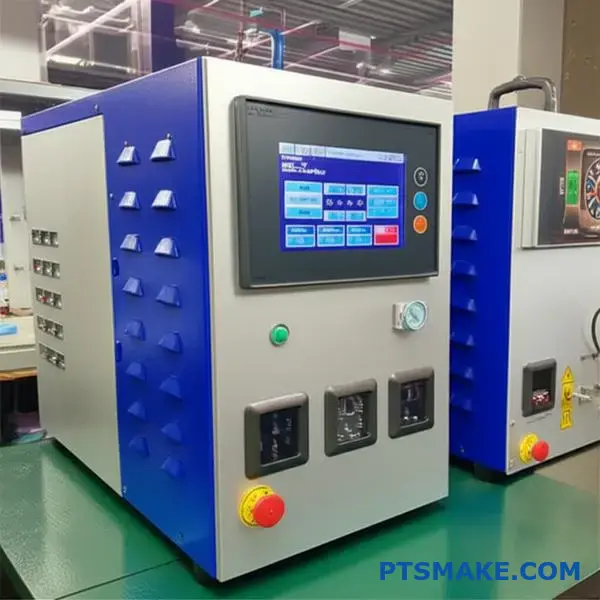
What types of feedback controls exist on modern welders?
Modern welders offer precise control over the joining process. Selecting the right control mode is key for consistent results. It’s not a one-size-fits-all situation.
Each mode provides a different way to manage the weld cycle. The choice depends on your materials, part geometry, and quality requirements.
Comparing Key Control Modes
Understanding the best use case for each mode prevents common welding defects. It ensures stability in your production line.
| Control Mode | Primary Function |
|---|---|
| Time | Welds for a fixed duration. |
| Energy | Delivers a preset amount of energy. |
| Peak Power | Stops welding at a target power level. |
| Distance | Welds until a specific collapse is met. |
This choice directly impacts the final product quality.
A Practical Guide to Control Modes
Choosing the right control is a critical step. It ensures that every weld meets strict specifications. This is especially true for high-precision applications. In past projects at PTSMAKE, we’ve seen how a mode change can solve persistent quality issues.
Time Mode
This is the most basic control. The welder runs for a pre-set amount of time. It’s simple and repeatable for applications where part and material consistency is very high. However, it cannot compensate for variations.
Energy Mode
Energy mode delivers a specific amount of electrical energy to the weld. This mode is excellent for compensating for minor variations in part surface or material. It’s often used in ultrasonic metal welding to ensure a solid molecular bond is formed.
Peak Power Mode
Here, the weld cycle stops once a pre-determined power level is reached. This is useful for protecting delicate components from overpowering. It prevents overheating or damage.
Distance / Collapse Mode
This mode offers the most direct physical feedback. The process stops once the specified weld collapse6 is measured. This ensures consistent joint strength and final assembly dimensions. It is ideal for critical applications.
| Control Mode | Best Use Case | Key Benefit |
|---|---|---|
| Time | Highly consistent parts, simple joints. | Simplicity and speed. |
| Energy | Parts with minor surface variations. | Compensates for inconsistencies. |
| Peak Power | Delicate or heat-sensitive electronics. | Prevents component damage. |
| Distance | Critical assemblies requiring dimensional accuracy. | Guarantees mechanical integrity. |
Choosing the correct control mode—Time, Energy, Power, or Distance—is fundamental for process stability. The best choice is always tied to the specific application, materials, and quality requirements to ensure consistent, reliable welds every time.
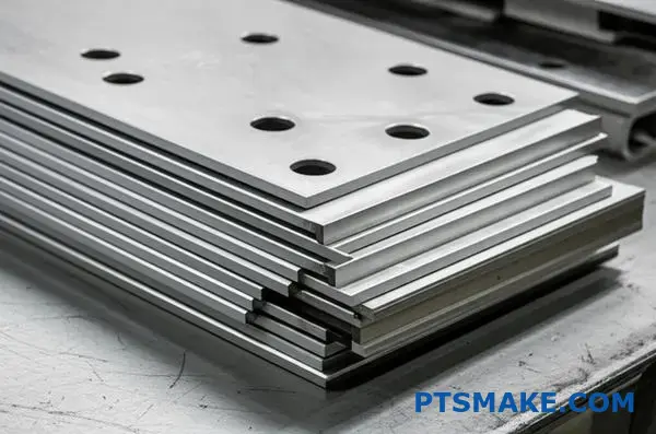
How does workpiece thickness influence parameter selection?
Total weld stack thickness is a major factor. Thicker materials present a significant hurdle for successful welds. They demand much more energy to create a solid bond.
This isn’t just about turning up the power. Parameter selection becomes a delicate balance. We must consider power, frequency, and even tooling design to get it right.
Key Parameter Shifts
Greater thickness requires a fundamental shift in approach.
| Factor | Thin Workpiece | Thick Workpiece |
|---|---|---|
| Power | Lower | Higher |
| Tooling | Standard | More Robust |
Overcoming Energy Dissipation
When welding thicker materials, more vibrational energy is lost. It dissipates as heat throughout the workpiece instead of focusing at the weld interface. This effect is a form of material damping7. To create a strong bond, you must overcome this energy loss.
Adjusting Power and Frequency
To compensate, the system needs to deliver more power. This creates a higher amplitude of vibration. We often find that lower frequencies, such as 20 kHz, perform better than 40 kHz on thicker stacks. The larger motion helps transmit energy through the material more effectively.
Typical Parameter Adjustments
Our experience in past projects shows a clear trend.
| Parameter | Thin Stack (<1mm) | Thick Stack (>3mm) |
|---|---|---|
| Power | Low to Medium | High |
| Frequency | 40 kHz or 30 kHz | 20 kHz or 15 kHz |
| Amplitude | Lower | Higher |
| Tooling | Standard Design | Reinforced/Robust |
The Need for Robust Tooling
The increased force and amplitude place immense stress on the tooling. Standard horns and anvils can crack or fail under these conditions. At PTSMAKE, we engineer more robust tooling for these applications. This is critical for consistent performance in ultrasonic metal welding and prevents costly equipment failure.
Welding thicker materials requires careful system calibration. Key adjustments include higher power, lower frequency, and more durable tooling. This approach effectively manages the increased energy demands and ensures a strong, reliable bond for the workpiece.
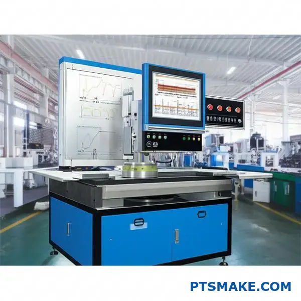
What is the structure of a comprehensive weld quality monitoring system?
A truly comprehensive system moves beyond simple visual checks. It relies on real-time data to create a digital signature for every single weld. This is the core of modern quality control.
Monitoring key data points gives us an instant health check. It allows us to see inside the process as it happens.
Key Real-Time Data Points
Here are the critical metrics we track:
| Data Point | What It Measures |
|---|---|
| Power Curve | The energy consumed throughout the weld cycle. |
| Final Collapse | The final thickness of the welded materials. |
| Frequency Shift | Changes in the system’s resonant frequency. |
This data provides a complete picture of weld integrity.
To ensure quality, we don’t just collect data; we use it to make automated decisions. Each weld generates a unique signature based on power, collapse, and frequency.
In our work at PTSMAKE, we establish a "golden" weld signature. This is based on extensive testing and analysis of perfect parts. This signature becomes our benchmark for quality.
From Data to Automated Rejection
We then apply control limits around this benchmark. This process is often called parameter windowing8. Any weld that produces a signature outside these defined limits is automatically flagged.
This system doesn’t guess. If a part’s data deviates, it is immediately rejected or sorted for review. This is crucial for high-volume production. It ensures that no suspect part slips through.
For processes like ultrasonic metal welding, this precision is non-negotiable.
Detecting Common Defects
Here’s how data deviations can indicate specific problems:
| Data Deviation | Potential Defect |
|---|---|
| Low Power | Insufficient energy, weak bond |
| High Collapse | Over-welding, material damage |
| Atypical Frequency | Contamination, poor part fit |
This automated approach eliminates human error. It also provides a full digital record for traceability, which is vital for our clients in the medical and automotive sectors.
Real-time data transforms weld monitoring from a reactive to a proactive process. By tracking key metrics, we can automatically detect and reject suspect parts, ensuring consistent quality and complete traceability for every component produced.
Analyze a failed battery tab weld: what is your process?
When a battery tab weld fails, the first question is always "why?". A high-resistance reading is a clear symptom, but not the cause.
My process avoids guesswork. It’s a systematic investigation built on four pillars. This structure helps us move from symptom to solution efficiently.
The Four Pillars of Analysis
We start with the simple things first. Then we move to more complex analyses. This saves time and resources.
Here is a quick overview of my initial approach.
| Analysis Pillar | Primary Focus |
|---|---|
| Visual Inspection | Surface-level defects, discoloration, alignment |
| Weld Data Review | Recorded parameters during the weld cycle |
| Destructive Testing | Internal structure and bond strength |
| Material Review | Contamination, thickness, and composition |
This methodical plan ensures we don’t miss crucial evidence.
Formulating a Root Cause Plan
A comprehensive plan is essential. We start by analyzing the weld data from the machine. Did the power, time, or collapse distance deviate from the set parameters? This data often provides the first clue.
Then, we move to destructive testing. This is non-negotiable for finding the true cause. A simple peel test can quantify the weld’s strength. But to see inside, we need more advanced methods.
Deep Dive with Destructive and Material Analysis
This is where my team at PTSMAKE excels. We perform a cross-section of the weld nugget. This allows for metallographic analysis9, revealing the internal structure under a microscope. We look for voids, cracks, or insufficient bonding at the weld interface.
This step is critical in processes like ultrasonic metal welding. It confirms if a true metallurgical bond was formed. Finally, we review the raw materials. Were the nickel tabs or copper foils contaminated with oils or oxides?
This comprehensive approach is laid out in the table below.
| Test Method | Key Objective | Potential Finding |
|---|---|---|
| Peel Test | Quantify weld strength | Low N-force indicates a weak bond |
| Cross-Section | View internal structure | Voids, poor material flow, micro-cracks |
| SEM/EDX Analysis | Check material purity | Surface contaminants, incorrect alloy |
Combining these methods gives us a complete picture of the failure.
A structured root cause analysis is key. By combining visual checks, weld data, destructive testing, and material review, we can move beyond symptoms to identify the true failure mechanism. This ensures any corrective actions are effective and lasting.
Critique a sonotrode design for a complex, multi-layer foil weld.
Let’s evaluate a hypothetical sonotrode design. This is crucial for complex multi-layer foil welding.
The design aims for a strong, consistent bond. Success depends entirely on the tool’s geometry.
Key Design Elements
A contoured surface ensures even contact. Energy directors are included to focus ultrasonic vibrations precisely. This combination is common.
But, is it optimal for delicate, layered foils? We must look deeper.
| Feature | Intended Purpose |
|---|---|
| Contoured Surface | Distribute clamping pressure evenly |
| Energy Directors | Concentrate energy at the weld interface |
| Hardened Steel | Provide durability and wear resistance |
Analyzing Potential Failure Points
A critical eye reveals potential problems. Even a well-intentioned design can fail under pressure, especially in ultrasonic metal welding. The interaction between the sonotrode, foils, and anvil is complex.
The contoured surface might not match the foil stack-up perfectly. This can cause uneven pressure distribution, leading to weak spots or overwelding in certain areas. It’s a common issue we’ve addressed in past projects at PTSMAKE.
Energy directors, if too sharp, can easily tear the top foil layer before a proper weld is even formed. The material’s acoustic impedance10 also plays a huge role here. A mismatch between the sonotrode and the workpiece can reflect energy instead of transmitting it.
Path to an Improved Design
Instead of sharp directors, we could use a micro-textured surface. This provides grip and focuses energy without damaging the foil.
Based on our test results, Finite Element Analysis (FEA) is also invaluable. It helps simulate heat and pressure, allowing us to refine the sonotrode contour digitally before any metal is cut.
| Potential Failure | Probable Cause | Suggested Improvement |
|---|---|---|
| Uneven Welding | Poor pressure distribution | Refine contour using FEA simulation |
| Foil Tearing | Aggressive energy directors | Replace with micro-textured surface |
| Weak Bond | Energy reflection | Match sonotrode material to foil stack |
A theoretical critique reveals critical flaws. By predicting failures like foil tearing and suggesting data-driven improvements, we can create a far more robust design for a reliable process.
How would you approach welding a novel or ‘unweldable’ alloy?
When faced with a novel material, you can’t just guess. You need a plan. A Research and Development (R&D) plan is our roadmap. It turns an unknown challenge into a series of manageable steps.
This structured approach is how we tackle feasibility studies at PTSMAKE. It ensures we get reliable data. It’s the first step to making the "unweldable" weldable.
Initial R&D Phases
Our plan starts with understanding the basics. We break down the problem into key phases.
| Phase | Objective |
|---|---|
| Phase 1 | Material Characterization |
| Phase 2 | Baseline Parameter Testing |
| Phase 3 | New Technique Development |
A Deeper Dive into Experimental Design
The core of our R&D plan is designing smart experiments. We must isolate variables to see what truly works. For any new alloy, we begin by establishing a baseline. This tells us how the material behaves under standard conditions.
We then methodically test the limits. The goal is to find a stable "welding window." This is the specific combination of settings that produces a strong, reliable bond. The entire process hinges on creating enough heat and material flow through interfacial friction11 without melting the metal.
Exploring Welding Parameters
In our collaborative research with clients, we have found that a systematic approach is key. We adjust one variable at a time to map its effect on weld quality. This data-driven process is crucial for success with ultrasonic metal welding.
| Variable | Range of Test | Expected Impact |
|---|---|---|
| Amplitude | Low to High | Controls vibrational energy and heat generation. |
| Pressure | Low to High | Ensures intimate contact between surfaces. |
| Weld Time | Short to Long | Determines the duration of energy application. |
This detailed testing helps us develop new techniques. These might include custom horn designs or surface preparation methods tailored specifically to the novel alloy.
A structured R&D plan is the only way to tackle "unweldable" alloys. It provides the clear, data-backed path needed to develop innovative welding solutions and turn difficult manufacturing challenges into successful outcomes for our clients.
How does ambient temperature and humidity affect process stability?
Significant environmental shifts can disrupt even the most stable processes. Temperature and humidity are silent variables. They can alter the very physics of your setup.
These factors directly influence both the ultrasonic stack and the materials you work with.
Impact on Key Components
Changes in temperature cause materials to expand or contract. This alters the resonant frequency of the ultrasonic stack. Humidity can also affect certain materials.
A stable environment is crucial for consistent results.
| Factor | Effect on Ultrasonic Stack | Effect on Workpiece |
|---|---|---|
| Temperature | Alters resonant frequency | Changes material properties |
| Humidity | Can cause corrosion on components | Affects hygroscopic materials |
The Physics Behind the Problem
The ultrasonic stack is tuned to a precise resonant frequency. When temperature changes, the components expand or contract. This change in physical dimensions directly shifts the frequency. A frequency mismatch reduces welding efficiency and consistency.
Workpiece materials are also vulnerable. Temperature affects their plasticity and hardness. Humidity can introduce moisture, which is especially problematic for polymers. This alters the material’s acoustic impedance12, affecting energy transfer.
Mitigation Strategies for Sensitive Processes
In past projects at PTSMAKE, we’ve found that proactive control is essential. For high-stakes applications like ultrasonic metal welding, you cannot leave the environment to chance. Small variations can lead to significant quality issues.
We’ve helped clients implement robust strategies to counter these effects.
| Strategy | Description | Benefit |
|---|---|---|
| Climate Control | Implement HVAC systems to maintain stable temperature and humidity levels. | Prevents frequency drift and material changes. |
| Regular Recalibration | Periodically check and adjust the system’s resonant frequency. | Ensures optimal energy delivery. |
| Material Pre-conditioning | Store workpiece materials in a controlled environment before processing. | Stabilizes material properties. |
| Real-time Monitoring | Use sensors to track environmental conditions and system performance. | Allows for immediate adjustments. |
By adopting these measures, you can insulate your process from environmental variables. This ensures predictable and repeatable outcomes.
Significant environmental changes directly impact resonant frequency and material properties. Controlling temperature and humidity is critical for maintaining process stability and ensuring the quality of the final product.
Unlock Your Ultrasonic Metal Welding Success with PTSMAKE
Ready to solve your toughest ultrasonic metal welding challenges? Contact PTSMAKE today for a rapid quotation—our experts help you overcome weldability issues, optimize application parameters, and deliver repeatable, precision results. Let’s build quality solutions together—send your inquiry now!

Learn more about the micro-mechanisms that enable solid-state welding bonds. ↩
Learn how this phenomenon allows strong welds without melting the metal. ↩
Discover the science behind these compounds and why they impact joint strength in dissimilar material welding. ↩
Discover how this core principle dictates heat generation and weld quality in ultrasonic applications. ↩
Learn how this microscopic boundary layer is critical to material bonding and overall weld integrity. ↩
Learn how this measurement ensures consistent joint strength and final part dimensions. ↩
Learn how material properties influence the absorption and dissipation of vibrational energy during welding. ↩
Learn how setting precise digital limits ensures 100% in-process quality control. ↩
Discover how microscopic examination reveals hidden defects and confirms weld integrity. ↩
See how this property impacts energy transfer and weld integrity. ↩
Learn more about how friction is key to forming solid-state bonds in ultrasonic welding. ↩
Learn more about how this property influences ultrasonic energy transfer efficiency. ↩