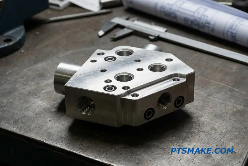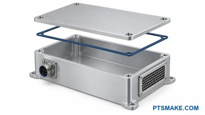

Liquid cooling promised to solve data center heat. But now leaking couplings, failed seals, and unplanned downtime are eating millions in damaged servers and lost uptime.
CNC machined quick disconnect couplings deliver ±0.005mm precision, dry-break sealing, and 100,000+ cycle life for data center liquid cooling. They outperform cast couplings in leak resistance, flow rate, and longevity—critical for high-density AI racks.
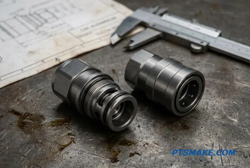
I’ve worked with hardware teams scaling liquid cooling from prototype to production. The coupling is where most projects stumble. Let me walk you through what actually matters when sourcing QD couplings for your next rack design.
Data Center Liquid Cooling Has a Bottleneck Problem — and It’s Not the Cold Plate
As rack densities in AI data centers push beyond 80kW, liquid cooling is no longer optional. The industry’s focus has been on improving cold plate and CDU efficiency. However, the system’s true weak link is often the fluid interconnect layer where components meet.
The Critical Interface
Quick Disconnect Couplings (QDs) are at the heart of this challenge. They are the primary interface for servicing and scaling liquid-cooled racks, making their reliability paramount. A single failure here can take down an entire rack of expensive hardware.
Evolving Industry Standards
The demands on these small components are increasing rapidly, driven by industry-wide trends. These standards dictate the performance required for modern data center liquid cooling interconnects.
| Trend | Implication for Couplings |
|---|---|
| OCP UQD Standard | Drives interoperability and universal design needs. |
| Tool-Free Maintenance | Requires robust and ergonomic locking mechanisms. |
| Zero-Downtime Goals | Mandates perfect dry-break performance to protect hardware. |
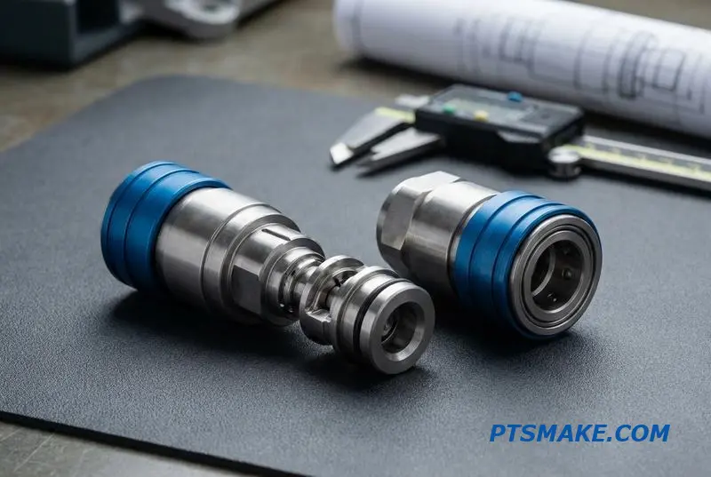
Many designs for Quick Disconnect Couplings look great on paper but falter under real-world conditions. The issue isn’t just about preventing catastrophic leaks; it’s also about preventing the slow, seeping failures that can go unnoticed until it’s too late.
Unpacking Common Failure Points
Reliability issues often trace back to manufacturing compromises. For instance, poor surface finishes on internal sealing faces or minute dimensional inaccuracies in valve components can create pathways for fluid to escape under pressure. These are not design flaws but execution failures.
The Importance of Material Science and Precision
Material choice is another critical factor. The interaction between the coolant, the seals, and the metal body of the coupling is a complex dynamic. The study of Tribology1 informs how we design mating surfaces to minimize wear and prevent galling during connection and disconnection cycles.
At PTSMAKE, we’ve seen how precise CNC machining directly addresses these rack-level cooling failure points. Tolerances measured in microns are not just for show; they are essential for ensuring a perfect seal every time.
| Failure Mode | Common Root Cause | Prevention Strategy |
|---|---|---|
| Weeping or Seeping | Inconsistent seal compression. | High-precision machining of seal glands. |
| Connection Difficulty | Tolerance stacking in components. | Strict process control and inspection. |
| Spillage on Disconnect | Poor valve timing or geometry. | Precise manufacturing of valve components. |
While cold plates and CDUs are vital, the system’s operational integrity hinges on its smallest parts. The reliability of Quick Disconnect Couplings is the true bottleneck, directly impacting uptime, maintenance costs, and the overall success of a liquid cooling deployment.
What Makes a Quick Disconnect Coupling CNC Machined — and Why It Matters
Quick disconnect couplings are often overlooked, yet they are critical in many systems. Their reliability depends entirely on how they are made. While standard cast or forged couplings are common, CNC machined alternatives offer a distinct advantage in performance and longevity, especially in demanding applications.
The Standard Approach: Casting and Forging
Most off-the-shelf quick disconnect couplings are produced through casting or forging. These methods are cost-effective for mass production but often fall short on precision. The result is a component that performs its basic function but may lack the refinement needed for high-pressure or high-cycle environments.
The Precision Alternative: CNC Machining
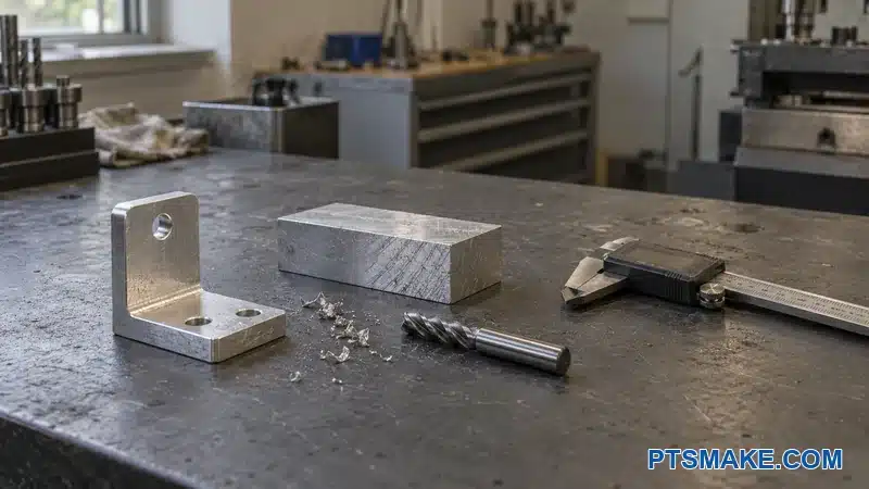
CNC machining creates parts from a solid block of material. This process provides unparalleled control over the final dimensions and surface quality. For a fluid connector, this precision is not a luxury; it is essential for a reliable seal and smooth operation over thousands of cycles.
| Feature | Cast/Forged Couplings | CNC Machined Couplings |
|---|---|---|
| Tolerance | Looser, often inconsistent | Tight, up to ±0.005mm |
| Surface Finish | Rougher, can wear seals | Smooth, controlled Ra |
| Internal Geometry | Simple, limited flow paths | Complex, optimized for flow |
| Material Integrity | Potential for porosity | Solid, uniform structure |
The debate of CNC vs cast quick disconnect couplings comes down to application demands. A cast part might have microscopic voids or a rougher surface finish. This directly impacts the O-rings and seals, leading to premature wear and potential leaks. A poor surface finish can quickly destroy a seal.
Surface Finish and Seal Longevity
The quality of the machined coupling surface finish (Ra) is critical. A smoother surface, achieved through precise CNC machining, allows seals to function effectively without abrasion. In our tests at PTSMAKE, we have seen that a superior finish can extend the life of a coupling’s seals significantly.
Material Performance is Not Automatic
Using a premium material like 316 stainless steel is only half the battle. Its corrosion resistance and strength mean little if the machining process is flawed. CNC machining ensures the material’s properties are fully realized, providing the reliability expected from high-grade alloys, especially in precision machined fluid connectors.
The internal geometry of a coupling also affects fluid dynamics. With CNC machining, we can create complex internal pathways that minimize turbulence and pressure drop. This optimization is impossible with casting. Performance under repeated use can also show material memory effects, where Hysteresis2 in the sealing material can lead to connection inconsistencies over time.
| Parameter | Impact of CNC Machining |
|---|---|
| Seal Life | Extended due to smooth surface finish |
| Leak Prevention | Enhanced by tight tolerances on sealing surfaces |
| Flow Efficiency | Improved with optimized internal channels |
| Durability | Maximized by preserving material integrity |
CNC machining provides the precision necessary for reliable, high-performance quick disconnect couplings. This process yields tighter tolerances, superior surface finishes, and design flexibility, ensuring longevity and optimal performance that cast or forged alternatives cannot match in critical applications.
UQD, QD, and QDC — Understanding the Alphabet Soup of Data Center Coupling Standards
In data center liquid cooling, acronyms like UQD, QD, and QDC can cause confusion. These terms define different types of quick disconnect couplings, but their specifications are not always interchangeable. Understanding the nuances is crucial for engineers and procurement managers.
What Do These Acronyms Mean?
A simple mistake in sourcing can lead to leaks or system failures. Each standard has a specific role, and knowing the difference prevents costly errors. Let’s break down what each of these acronyms stands for in the context of data center hardware.
Quick Comparison
| Acronym | Full Name | Primary Function |
|---|---|---|
| UQD | Universal Quick Disconnect | OCP-compliant form factor for server racks |
| QD | Quick Disconnect | General term for any quick-release connector |
| QDC | Quick Disconnect Coupling | Specific term for fluid or gas line connectors |
| BMQC | Blind Mate Quick Connector | Connectors designed for blind mating |
This table provides a high-level overview. Sourcing the correct component requires a deeper understanding of their application and limitations, especially when dealing with custom solutions.
Diving Deeper into the Standards
Let’s clarify the key distinctions. While these terms are related to quick disconnect couplings, they are not synonyms. The primary source of confusion often comes from the "Universal" in UQD, which can be misleading.
UQD: An OCP Standard Form Factor
The Universal Quick Disconnect (UQD) is a standard defined by the Open Compute Project (OCP). It specifies the form factor for connectors used in liquid-cooled server racks. This ensures that a UQD-compliant manifold can accept a UQD-compliant server.
However, it does not guarantee interoperability3 between components from different manufacturers. Dimensions, materials, and performance can still vary significantly. When sourcing replacements or custom parts, you cannot assume one UQD connector will work with another brand’s system.
QD, QDC, and BMQC
QD (Quick Disconnect) is a generic term, while QDC (Quick Disconnect Coupling) specifically refers to couplings for fluid transfer. A Blind Mate Quick Connector (BMQC) is designed for connections made without direct visibility, common in dense server racks.
The main challenge in UQD vs BMQC data center applications is ensuring a perfect seal under blind-mate conditions. At PTSMAKE, we often machine custom quick disconnect couplings that meet OCP form-factor requirements but are optimized for a specific client’s performance and material needs.
| Feature | UQD (per OCP) | General QDC/BMQC |
|---|---|---|
| Standard | OCP-defined form factor | Varies by manufacturer and application |
| Compatibility | Limited to form factor, not internal parts | Typically brand-specific unless stated otherwise |
| Use Case | OCP-compliant liquid cooling racks | Broad industrial and data center applications |
This variability is why precise engineering and manufacturing are critical. A slight deviation in tolerance can compromise the entire cooling loop, risking equipment worth millions.
Understanding these coupling standards is essential. UQD compliance only standardizes the form factor, not universal compatibility. Always verify manufacturer specifications for internal dimensions and performance to ensure system integrity and prevent leaks in critical liquid cooling applications.
When Off-the-Shelf UQD Couplings Don’t Fit — Custom Machining Scenarios
Standard Quick Disconnect Couplings are incredibly useful, but they don’t solve every engineering problem. When off-the-shelf parts from major suppliers fail to meet unique system requirements, custom CNC machining becomes essential. This is where precision manufacturing offers a direct solution.
Unique Space Constraints
Compact designs often leave no room for standard fittings. A shorter overall length or a specific angle might be necessary to fit within a tight enclosure. Custom machining allows for tailored dimensions that integrate perfectly.
Material Incompatibility
Standard materials like brass or stainless steel are not always suitable. Applications involving corrosive fluids or specific thermal properties demand specialized materials that are not available in standard catalogs.
| Feature | Standard UQD Coupling | Custom Machined UQD |
|---|---|---|
| Geometry | Fixed, standard sizes | Fully customizable length & shape |
| Material | Limited to common alloys | Wide range (PEEK, Titanium, etc.) |
| Integration | Requires adapters | Direct fit into manifolds |
| Threads | Standard NPT, BSP, etc. | Any custom or hybrid thread |
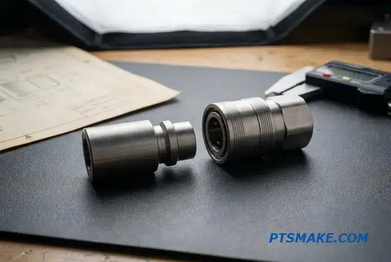
Off-the-shelf Quick Disconnect Couplings fall short in several real-world scenarios. We often see this with custom manifold integration, especially in complex hydraulic or liquid cooling systems. A standard part may require multiple adapters, increasing potential leak points and assembly complexity.
Custom Manifold and Port Configurations
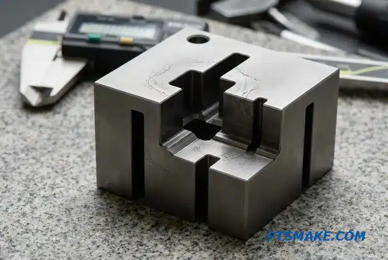
Machining a bespoke data center fluid connector directly into a manifold block eliminates these issues. This creates a stronger, more reliable connection with a smaller footprint. It also simplifies the system architecture, which is a significant advantage in high-density applications like server racks.
Non-Standard Threads and Fittings
Another common challenge is interfacing with legacy or specialized equipment that uses non-standard thread types. Instead of searching for rare adapters, we can machine non-standard quick disconnect fittings with the exact threads needed, whether they are metric, NPT, or a proprietary design.
Specialized Material Needs
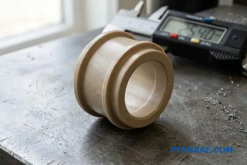
Material requirements also drive customization. For example, a project involving a dielectric4 fluid for electronics cooling required couplings made from PEEK. This material provides electrical insulation that standard metal couplings cannot offer, preventing short circuits and ensuring system safety.
When standard Quick Disconnect Couplings fail due to unique geometry, material, or integration needs, custom CNC machining is the solution. It provides tailored parts that fit perfectly, perform reliably, and meet the exact specifications of the most demanding applications.
Material Selection for Data Center Quick Disconnect Couplings — 316 Stainless, Brass, and PEEK
Choosing the right material for Quick Disconnect Couplings is critical for data center liquid cooling reliability. Your decision impacts longevity, cost, and safety. While many options exist, the application’s specific demands—coolant type, pressure, and environment—should always guide your selection process.
Gold Standard vs. Budget-Friendly
For mission-critical systems, 316 stainless steel is the undisputed choice. Its superior corrosion resistance ensures long-term performance, preventing costly leaks. Brass, on the other hand, offers a significant cost advantage for less critical cooling loops where performance demands are lower.
Material Trade-offs Overview
| Feature | 316 Stainless Steel | Brass |
|---|---|---|
| Corrosion Resistance | Excellent | Good |
| Cost | Higher | Lower |
| Strength | High | Moderate |
| Best Use Case | Mission-critical loops | Non-critical systems |
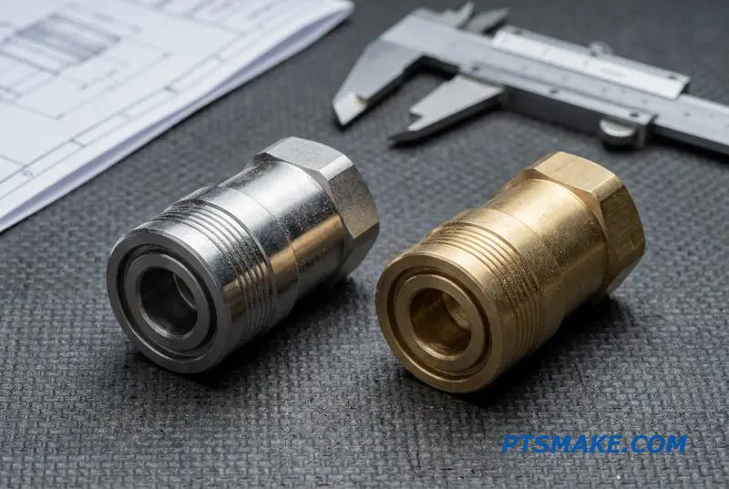
Beyond metals, polymers like PEEK and PTFE are essential when dealing with dielectric fluids. These materials prevent electrical conductivity, a key requirement for certain cooling architectures. A PEEK quick disconnect fitting offers excellent chemical resistance and high strength, making it ideal for specialized applications.
The Critical Role of Seals
Material selection extends to the seals within the Quick Disconnect Couplings. The compatibility between the seal and the coolant is paramount. EPDM seals are excellent for glycol-water mixtures, but they degrade quickly when exposed to dielectric fluids. For those applications, FKM is the preferred choice.
Seal and Coolant Compatibility
| Seal Material | Glycol-Water Coolant | Dielectric Fluid |
|---|---|---|
| EPDM | Highly Compatible | Not Compatible |
| FKM (Viton) | Compatible | Highly Compatible |
We often see failures caused by mismatched materials. In high-humidity data centers, using dissimilar metals like brass and a stainless steel UQD coupling in the same loop can lead to Galvanic corrosion5. This electrochemical process accelerates degradation, leading to premature leaks and system downtime. At PTSMAKE, we guide clients through these nuances to ensure system integrity.
Choosing the right material for Quick Disconnect Couplings involves a careful balance of cost, coolant compatibility, and environmental factors. From 316 stainless steel to PEEK and the right seal material, each component is critical for long-term data center cooling reliability.
Dry-Break and Non-Spill Technology — Why Every Drop Matters in a Server Rack
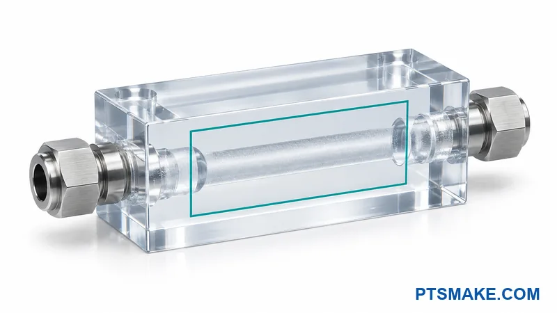
In a data center, one drop of coolant can cause a catastrophic short circuit. This is why non-spill Quick Disconnect Couplings are a necessity, not a luxury. These couplings are engineered to prevent fluid loss during connection or disconnection, protecting sensitive electronics.
Why Standard Couplings Fail
Traditional couplings often leave a small residue of fluid upon disconnection. In a server rack, this is an unacceptable risk. Dry-break technology aims for a "zero-leak" performance, which is the benchmark for mission-critical applications where system uptime is paramount.
Flat-Face vs. Poppet-Style Valves
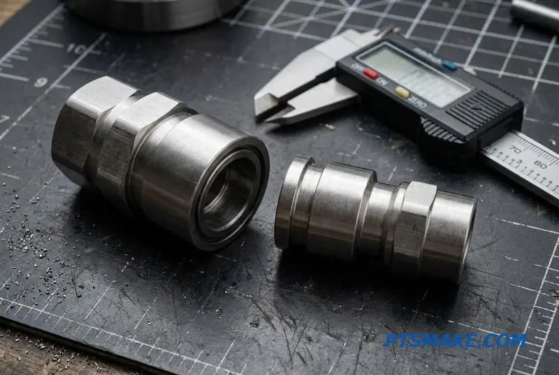
The valve design inside a Quick Disconnect Coupling dictates its performance. Many older designs use a Poppet valve6, which can trap a small amount of fluid between internal components. This trapped fluid results in minor spillage during disconnection.
The Superiority of Flat-Face Design
A flat-face dry break quick disconnect is the superior solution for data center applications. This design brings two perfectly flat surfaces together, creating a tight seal before the internal valves open. This virtually eliminates the "dead volume" where fluid can be trapped, ensuring a clean break.
| Feature | Poppet-Style Valve | Flat-Face Dry-Break Valve |
|---|---|---|
| Spillage | Minor spillage on disconnect | Near-zero spillage |
| Air Inclusion | Allows some air in on connect | Minimal air inclusion |
| Application | General hydraulics | Data centers, electronics |
| Precision Need | Moderate | Very High |
Precision Machining for Zero Leaks
The effectiveness of a flat-face non-spill coolant coupling depends entirely on its sealing surfaces. At PTSMAKE, we rely on precision CNC machining to achieve the extremely tight tolerances required for a perfect seal. We then validate performance with helium leak testing to guarantee integrity.
In data center cooling, non-spill flat-face Quick Disconnect Couplings are essential for mitigating risk. Their reliability over older poppet-style designs comes directly from the precision of CNC machining, which is validated by rigorous methods like helium leak testing to ensure absolute safety.
Tolerance Matters — How ±0.005mm Machining Affects Coupling Performance
When designing Quick Disconnect Couplings, tolerance isn’t just a number; it’s the foundation of performance. A loose tolerance directly compromises seal integrity. It creates uneven gaps, leading to seal extrusion under pressure and eventual leakage. This is a common failure point I’ve seen in many designs.
Seal Life and Insertion Force
Even slight deviations cause seals to wear unevenly, drastically shortening their operational life. Furthermore, inconsistent internal dimensions increase the force needed to connect and disconnect the coupling. This makes operation difficult and can damage components over time.
| Tolerance Impact | Loose Tolerance (+/- 0.1mm) | Tight Tolerance (+/- 0.005mm) |
|---|---|---|
| Seal Wear | Uneven, premature failure | Consistent, extended life |
| Insertion | High, inconsistent force | Smooth, low force |
| Leakage Risk | High | Minimal |
Vibration Resistance and Pressure Rating
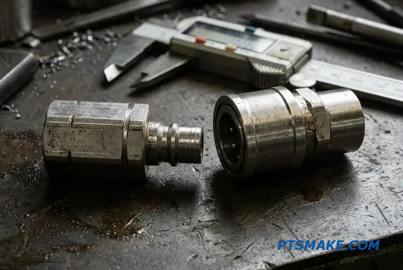
In high-vibration systems, loose tolerances allow micro-movements between mating parts. This can lead to Fretting7 and wear, compromising the connection. Tight, precise fits from CNC machining minimize this movement, ensuring the coupling remains secure and functional.
Pressure ratings are also directly tied to tolerance. A precise fit ensures that forces are distributed evenly across the locking mechanisms and seals. Our tests show this prevents localized stress points that could lead to catastrophic failure under high pressure. Casting simply cannot achieve this level of precision.
Manufacturing Method vs. Tolerance
| Manufacturing | Typical Tolerance Range | Performance Outcome |
|---|---|---|
| Casting | ±0.2mm to ±0.5mm | Inconsistent fit, lower pressure rating |
| CNC Machining | ±0.005mm to ±0.02mm | Reliable seal, high vibration resistance |
At PTSMAKE, we specialize in achieving these critical tolerances. This ensures every precision machined coupling delivers optimal seal life and performance from the first connection to the last, making it a reliable component for demanding applications.
Tight tolerances achieved through precision CNC machining are essential for Quick Disconnect Couplings. They directly enhance seal life, reduce insertion force, improve vibration resistance, and ensure the component meets its specified pressure rating, preventing premature failure.
Pressure, Flow Rate, and Pressure Drop — Engineering Specs Buyers Actually Need to Check
When evaluating quick disconnect couplings, especially for applications like data center liquid cooling, three performance specs matter most: pressure, flow rate, and pressure drop. Getting these right is critical for system efficiency and reliability. Focusing on them ensures you select a component that truly fits your design intent.
Key Performance Metrics
It’s easy to get lost in datasheets. However, these three values directly impact your system’s hydraulic performance. They determine pump sizing, cooling efficiency, and long-term operational costs.
| Specification | Typical Range (Data Center) | Importance |
|---|---|---|
| Operating Pressure | 150 – 300 psi | Ensures coupling integrity under system load. |
| Flow Rate | 10 – 30 L/min | Determines the volume of coolant moved per unit time. |
| Pressure Drop (ΔP) | < 5 psi | Measures the energy loss across the coupling. |
Why They are Interconnected
A low pressure drop at your target flow rate indicates an efficient coupling. This allows you to use a smaller, more energy-efficient pump, directly impacting your operational expenses and system footprint.
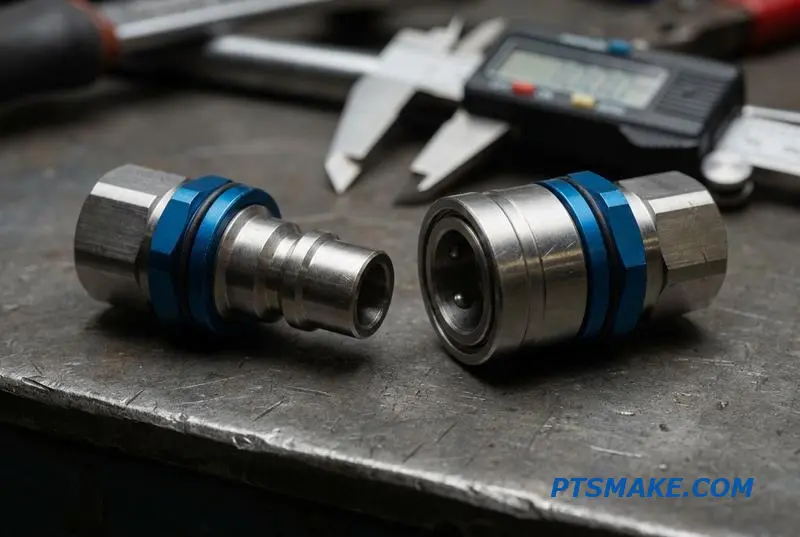
The hydraulic performance of a quick disconnect coupling isn’t magic; it’s pure engineering. The internal geometry dictates how fluid moves through it. Factors like internal bore diameter, surface finish, and the smoothness of the flow path are critical. A wider, smoother path minimizes turbulence, which in turn lowers pressure drop.
Impact of Internal Geometry
At PTSMAKE, our precision CNC machining allows us to create components with exceptionally smooth internal surfaces and optimized flow paths. This precision directly translates into better hydraulic performance for the couplings our parts are used in. It’s a tangible benefit that affects the entire system.
Flow Rate and Pump Sizing
Some manufacturers, like Danfoss, claim their designs offer up to 25% higher flow versus the OCP standard for the same pressure drop. This is significant. Higher flow efficiency means you can meet cooling requirements with a smaller, less powerful pump. This reduces both initial hardware costs and long-term energy consumption. This relationship is governed by principles like Bernoulli’s principle8, where fluid velocity and pressure are inversely related. An efficient coupling maintains higher pressure by minimizing velocity-inducing restrictions.
Selecting the right quick disconnect coupling requires a close look at operating pressure, flow rate, and pressure drop. These interconnected specs dictate system efficiency, influence pump selection, and ultimately impact your project’s overall cost and reliability.
Tool-Free Operation and Hot-Swap Capability — Design Features That Reduce Data Center Downtime
In data centers, downtime isn’t just an inconvenience; it’s a significant financial drain. Tool-free designs, especially for fluid connectors, are a direct response to this challenge. They simplify maintenance and reduce the time required for component replacement from hours to mere minutes, a critical factor in high-availability environments.
The Advantage of Speed
Quick disconnect couplings (QDCs) are central to this philosophy. By eliminating the need for wrenches or other tools, technicians can perform service tasks much faster. This directly minimizes the risk of extended system outages during routine maintenance or emergency repairs, safeguarding operational continuity.
Reducing Human Error
Simplifying the connection process also inherently reduces the potential for human error. A secure, tool-free connection provides clear tactile and often audible feedback, confirming a proper seal. This contrasts sharply with threaded connections, where over-tightening or under-tightening can easily lead to costly leaks.
| Feature Comparison | Traditional Screw-On | Tool-Free Quick Disconnect |
|---|---|---|
| Connection Time | 3-5 minutes per connection | <10 seconds per connection |
| Required Tools | Wrenches, torque tools | None |
| Risk of Error | High (cross-threading, torque) | Low (intuitive design) |
| Operator Skill | Moderate | Minimal |
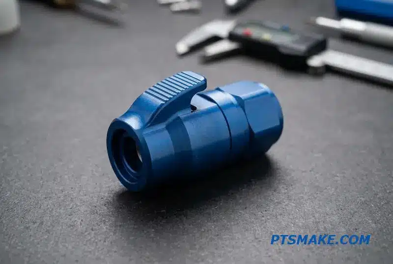
When selecting a tool-free UQD connector, the mechanism is key. Each design offers a different balance of security, ease of use, and application suitability. Understanding these differences is crucial for optimizing system performance and maintainability in a data center environment.
Comparing Connection Mechanisms
Push-to-connect designs offer speed, while screw-to-connect provides high security. Thumb-latch mechanisms strike a balance, offering both security and easy one-hand operated QD coupling functionality. The choice depends entirely on the specific application’s pressure, vibration, and accessibility requirements.
| Mechanism Type | Primary Advantage | Ideal Use Case |
|---|---|---|
| Push-to-Connect | Speed and simplicity | Low-pressure, frequent access |
| Screw-to-Connect | High-pressure security | Permanent or semi-permanent |
| Thumb-Latch | Secure, one-handed use | Rack-mounted systems, CDUs |
The Critical Role of Hot-Swapping
The hot swap quick disconnect coupling capability is non-negotiable for modern Cooling Distribution Units (CDUs). It allows technicians to connect or disconnect fluid lines while the system is under pressure. This eliminates the need for a complete system shutdown, ensuring continuous operation during maintenance.
How Precision Machining Enables Innovation
This is where our work at PTSMAKE becomes critical. Using CNC machining, we produce custom latching features with precise geometries that ensure reliable, drip-free connections. We focus on the Kinematics9 of the mechanism to create ergonomic thumb latches for blind mate data center coolant connections, which are often in tight, hard-to-see spaces. We are also seeing a trend, driven by the Open Compute Project (OCP), towards standardized push-lock hose connections.
Tool-free operation and hot-swap capability are no longer luxuries but necessities in data center design. By leveraging advanced connection mechanisms, enabled by precision manufacturing, operators can significantly reduce downtime, minimize human error, and enhance the overall reliability and efficiency of their cooling systems.
Why Surface Finish on the Seal Bore Is the Difference Between 10,000 and 100,000 Cycles
The surface finish inside a seal bore is a critical detail often overlooked. In my experience, it directly dictates the operational life of dynamic seals, especially in high-cycle applications like quick disconnect couplings. A smoother surface dramatically reduces friction and wear on O-rings.
Surface Finish (Ra) vs. Seal Life
The difference in performance is not minor. Based on tests we’ve conducted with our clients, moving from a standard to a fine finish can extend a seal’s life by an order of magnitude, preventing costly downtime and maintenance for fluid connector systems.
| Ra Value | Expected Seal Cycle Life | Common Machining Method |
|---|---|---|
| 1.6μm | ~10,000 cycles | Standard Turning |
| 0.8μm | ~30,000 cycles | Fine Turning |
| 0.4μm | >100,000 cycles | Precision Turning/Grinding |
Achieving Consistent Finishes
Achieving a consistent sub-micron finish requires precise CNC turning. It depends on selecting the right insert geometry, maintaining optimal cutting speeds, and using high-quality coolant. This control is what separates a reliable component from one that fails prematurely.
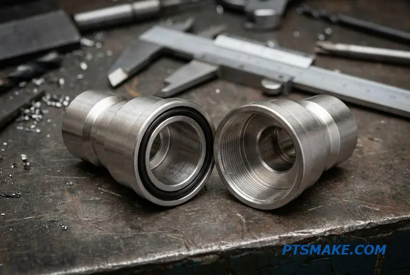
A rough seal bore surface finish (Ra) acts like fine-grit sandpaper on a dynamic O-ring. Every time the coupling is connected or disconnected, the seal rubs against the bore’s microscopic peaks and valleys. This constant friction causes steady wear and material degradation.
The Problem of Micro-Abrasion
This wear mechanism is known as micro-abrasion. The tiny, sharp surface features, or asperity10, on a poorly finished bore shear off microscopic particles from the O-ring. These particles don’t just disappear; they enter the fluid system, causing contamination.
Contamination in Closed-Loop Systems
In sensitive systems like coolant loops for medical or electronic equipment, this contamination is a major problem. The particles can clog filters, damage pumps, and reduce the thermal efficiency of the entire system, leading to unexpected failures far from the original seal.
| Surface Finish Issue | Resulting System Problem | Industry Impact |
|---|---|---|
| High Ra Value | Increased O-ring Wear | Shorter quick disconnect cycle life |
| Particle Shedding | Fluid Contamination | Reduced coolant efficiency |
| Seal Failure | System Leakage | Unplanned maintenance/downtime |
At PTSMAKE, we specialize in achieving Ra values below 0.4μm for clients whose applications demand extreme reliability and system cleanliness. We understand that CNC surface finish O-ring wear is a key factor in fluid connector seal durability.
Controlling seal bore surface finish is a critical engineering decision. It directly impacts seal wear, system contamination, and the operational life of components like quick disconnect couplings. A finer finish ensures far greater durability and reliability for the entire system.
CDU Integration — Designing Couplings That Work With Coolant Distribution Units
Coolant Distribution Units (CDUs) are the heart of any serious liquid cooling system. The quick disconnect couplings on their inlets and outlets are not just simple connectors; they are critical components that must perform flawlessly under constant stress.
Critical Performance Metrics
These couplings handle continuous flow, often at the system’s maximum rated pressure. Unlike couplings used for intermittent service, CDU connections must maintain a perfect seal without failure over thousands of hours of operation, ensuring system uptime.
Connection Security
Frequent connection and disconnection cycles during maintenance demand robust designs. This is why many CDU applications use screw-to-connect mechanisms. They provide an extra layer of security against accidental disconnection, which is vital in dense data center racks.
| Feature | Standard Coupling | CDU-Specific Coupling |
|---|---|---|
| Duty Cycle | Intermittent | Continuous |
| Connection Type | Push-to-connect | Screw-to-connect (often) |
| Pressure Rating | Varies | High, sustained |
| Leak Tolerance | Low | Near-zero |
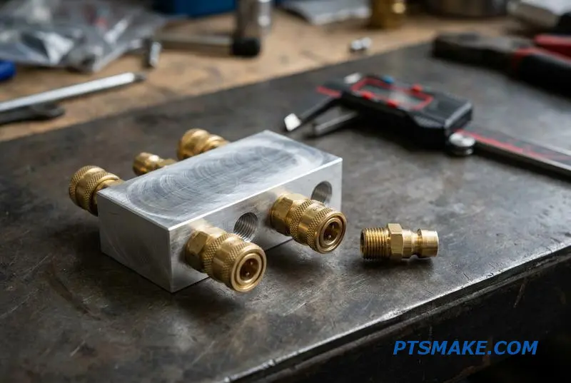
Specialized Coupling Solutions
Companies like CEJN exemplify a focused approach to CDU coupling design. They engineer solutions specifically for a high Volumetric flow rate11 with minimal pressure drop. This ensures the cooling system operates at peak thermal efficiency, a crucial factor in data center power usage effectiveness.
Integrating Couplings with CNC Machining
However, the coupling itself is only part of the equation. At PTSMAKE, we see the real innovation in integration. Instead of attaching separate couplings to a manifold, we use CNC machining to create custom aluminum or stainless steel manifold blocks with the quick disconnect receptacles machined directly into the unit.
This approach eliminates potential leak points at threaded connections. It also creates a more compact, reliable, and service-friendly coolant distribution unit. In our work with clients, this has reduced assembly time and improved overall system integrity.
| Approach | Pros | Cons |
|---|---|---|
| Discrete Couplings | Standardized parts | More potential leak points |
| Integrated Manifold | Compact, fewer seals | Requires custom machining |
| Highly reliable | Higher initial design cost |
In short, designing for CDU integration is a two-part challenge. It requires selecting robust, purpose-built quick disconnect couplings and leveraging precision manufacturing to create integrated manifolds. This combination is key to building reliable and efficient liquid cooling systems for critical applications.
Direct Liquid Cooling (DLC) and Cold Plate Connections — Getting the Interface Right
Direct Liquid Cooling (DLC) architectures require compact components. The connections between cold plates, manifolds, and the Coolant Distribution Unit (CDU) are critical. Space constraints inside a server chassis demand that Quick Disconnect Couplings have a minimal footprint, directly impacting system layout and serviceability.
Hand-Mate vs. Blind-Mate Couplings
Choosing the right coupling type is essential. Hand-mate couplings require manual connection, suitable for accessible areas. Blind-mate couplings are designed for racks where components slide into place without direct visual or physical access. The choice depends entirely on the service strategy and hardware layout.
Selection Criteria Breakdown
The decision involves balancing accessibility, cost, and reliability. Here is a simple comparison based on common project requirements.
| Feature | Hand-Mate Coupling | Blind-Mate Coupling |
|---|---|---|
| Accessibility | Requires direct access | Ideal for inaccessible areas |
| Alignment | Manual alignment needed | Self-aligning mechanism |
| Cost | Generally lower | Higher due to complexity |
| Application | Prototyping, open chassis | High-density server racks |
The Limits of Off-the-Shelf Parts
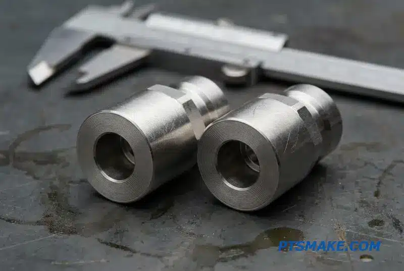
Standard Quick Disconnect Couplings often fail to meet the unique form-factor requirements of high-density DLC systems. Off-the-shelf parts can create integration challenges, forcing designers to compromise on layout, which can negatively impact airflow and thermal performance. This is a common issue I see.
Why Custom CNC Machining is the Solution
When standard parts don’t fit, custom CNC-machined couplings are the answer. At PTSMAKE, we create compact UQD connectors for DLC that resolve these conflicts. We can tailor the length, diameter, and port angles to fit perfectly within a server chassis, ensuring no wasted space. A precisely machined Elastomeric Seal12 groove, for example, is critical for leak-proof performance over thousands of cycles.
Custom vs. Standard: A Clear Advantage
Custom solutions provide more than just a better fit. After reviewing client test data, we’ve seen significant improvements in flow efficiency and long-term reliability.
| Aspect | Standard Couplings | Custom CNC-Machined Couplings |
|---|---|---|
| Fit | Generic, may not fit | Perfect fit for the application |
| Performance | Standard flow characteristics | Optimized for specific flow rates |
| Material | Limited material options | Wide selection for fluid compatibility |
| Integration | May require adapters | Direct integration, fewer parts |
Custom manufacturing for a DLC cold plate coupling eliminates compromises, leading to a more robust and efficient cooling system. This approach transforms a potential bottleneck into a strength.
Getting the interface right is crucial for DLC reliability. While standard parts have their place, custom CNC-machined Quick Disconnect Couplings often provide the only viable solution for achieving optimal performance and fit within the tight constraints of modern server hardware.
Immersion Cooling Fluid Connectors — Why Dielectric Compatibility Drives Material Choice
In immersion cooling systems, the choice of connector material is not just a detail—it’s fundamental to system reliability. Unlike traditional water-glycol setups, immersion cooling uses dielectric fluids. These fluids can cause standard seals, like EPDM, to swell, crack, or completely fail over time.
The Material Mismatch
Standard O-rings and seals are often designed for water or oils. Dielectric fluids, such as engineered fluids from 3M, have a completely different chemical makeup. This mismatch can lead to leaks, equipment damage, and costly downtime. Selecting the right material is essential from the start.
Required Material Properties
For a dielectric fluid compatible coupling, materials must offer both chemical inertness and mechanical stability. This is where advanced engineering plastics come into play.
| Material | Compatibility with Dielectric Fluids | Common Application |
|---|---|---|
| EPDM | Poor (Swelling/Degradation) | Water-Glycol Systems |
| FKM (Standard) | Moderate (Varies by grade) | Oil & Fuel Systems |
| PTFE | Excellent | Immersion Cooling Seals |
| PEEK | Excellent | Structural Components |
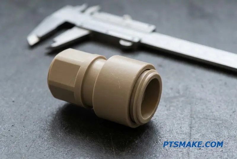
The demands of immersion cooling, especially two-phase systems, push material science to its limits. The wrong seal material in an immersion cooling quick disconnect doesn’t just wear out; it actively breaks down, compromising the entire closed-loop system. My team at PTSMAKE often encounters this issue during retrofits.
Single-Phase vs. Two-Phase Challenges
In single-phase cooling, the fluid remains liquid, requiring materials stable at operating temperatures. Two-phase cooling introduces boiling and condensation, adding intense thermal cycling. This cycling can stress materials, making properties like a low coefficient of thermal expansion critical.
Why PEEK and PTFE are Solutions
Materials like PEEK and PTFE are chemically inert to aggressive dielectric fluids. They maintain their structural integrity and sealing properties across a wide temperature range. A PEEK coupling for immersion cooling, for example, provides the required strength and compatibility. At PTSMAKE, we use precision CNC machining to shape these materials, as they cannot be molded like traditional plastics. This process ensures tight tolerances for a perfect seal. A key factor in material performance is its Glass transition temperature13, which defines its operational limits.
| Feature | PEEK | PTFE | FKM (Specialty) |
|---|---|---|---|
| Chemical Resistance | Excellent | Excellent | Very Good |
| Max Temp. | ~250°C | ~260°C | ~200°C |
| Machinability | Excellent | Good | N/A (Seals) |
| Best Use Case | Connector Bodies | Seals, Liners | High-Temp Seals |
In conclusion, material selection for immersion cooling quick disconnect couplings is critical. Dielectric fluid compatibility dictates the use of advanced plastics like PEEK and PTFE. Precision CNC machining is the enabling technology to manufacture these high-performance components for reliable, long-term operation.
OCP Compliance and Interchangeability — When to Follow the Standard and When to Deviate
The Open Compute Project (OCP) standardizes the UQD form factor to ensure interchangeability in data centers. This is crucial for maintenance and scalability. Following the Open Compute Project coupling standard allows any compliant part to replace another, simplifying logistics and reducing vendor lock-in.
The Standardization Dilemma
Adhering to OCP specifications offers clear benefits, but it isn’t always the optimal path. The decision depends heavily on the specific application and infrastructure goals. A new build might prioritize performance over interchangeability.
Key Decision Factors
Here is a breakdown of when to adhere versus when to customize:
| Scenario | Recommendation | Rationale |
|---|---|---|
| Existing OCP Infrastructure | Adhere to Standard | Ensures drop-in replacement and compatibility. |
| New Proprietary System | Consider Deviation | Allows for optimization of flow, size, or material. |
| Multi-Vendor Environment | Adhere to Standard | Guarantees interoperability between different suppliers. |
| Performance-Critical Application | Consider Deviation | A custom design may offer superior performance. |
This choice directly impacts the design and manufacturing of your Quick Disconnect Couplings.
The debate between compliance and customization is one I navigate frequently with clients. The primary driver for strict adherence to OCP compliant UQD dimensions is backward compatibility. If you’re servicing or expanding an existing data center built on OCP standards, using non-compliant parts is not an option. It breaks the entire model.
When Customization Makes Sense
However, for a new, self-contained system—like a proprietary liquid cooling manifold—deviating from the standard UQD form factor specifications can unlock significant advantages. You might redesign a coupling to reduce pressure drop, minimize its footprint, or use a specific material for fluid compatibility. Here, interchangeability with off-the-shelf parts is irrelevant.
At PTSMAKE, we handle both scenarios. Our CNC machines can replicate OCP-specified tolerances with extreme precision for clients needing interchangeable quick disconnect data center components. We can also partner on fully custom designs, optimizing every feature for a specific function. The manufacturing process is guided by the principles of Geometric Dimensioning and Tolerancing14 to ensure the final part performs exactly as intended, whether standard or custom.
The choice between OCP compliance and custom design depends on your system’s needs. Adherence ensures interchangeability for existing infrastructure, while deviation allows for performance optimization in new, controlled applications. Precision machining is vital for achieving the required specifications in either case.
Sourcing Custom QD Couplings From China — Quality Control, Lead Times, and IP Protection
Sourcing from China can be a concern for US and EU buyers. The main questions I hear revolve around trust, quality, and security. It’s crucial to partner with a supplier who understands these concerns and has robust systems in place to address them directly.
Quality Control You Can Trust
Reputable shops prove their commitment through transparent quality control. We implement multi-step verification for every batch of custom quick disconnect couplings. This isn’t just a final check; it’s a process integrated from start to finish.
Securing Your Intellectual Property
IP protection is non-negotiable. We ensure your designs are safe through legally binding agreements and internal security protocols that prevent unauthorized access or replication.
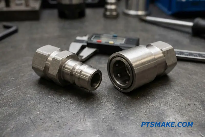
A reliable Chinese CNC machining supplier’s quality control is built on verifiable data. At PTSMAKE, we use Coordinate Measuring Machine (CMM) inspections to confirm that every dimension of your quick disconnect couplings meets the tightest tolerances specified in your designs.
Advanced Testing Protocols
For applications where sealing is critical, we perform helium leak testing to ensure absolute integrity. We also provide full material traceability with certifications like EN 10204 3.115, which validates the material’s chemical and mechanical properties directly from the source mill. This is how you can buy CNC machined couplings with confidence.
Lead Times and IP Protection
We’ve optimized our processes to deliver rapid results without compromising quality. The table below shows our typical timelines.
| Stage | Lead Time |
|---|---|
| Prototype | 5–7 Days |
| Production | 2–3 Weeks |
Your intellectual property is secured from day one. We start with a non-disclosure agreement (NDA) and often use separate production cells for sensitive projects. Our internal policies have no-exception clauses regarding IP, ensuring your designs remain confidential. This is standard for any serious custom coupling manufacturer in China.
Choosing the right partner means finding a supplier who provides transparent quality control, competitive lead times, and rigorous IP protection. A reputable Chinese manufacturer can meet and exceed the standards you expect for your custom quick disconnect couplings.
Thread Types, Port Configurations, and End Fittings — Getting the Connection Right
Choosing the right thread is the first step to a leak-proof connection. Mismatched threads, like NPT and BSPT, might seem to connect but will inevitably fail under pressure. This is a common issue we see causing significant downtime and rework for our clients.
Understanding Thread Standards
The differences between thread standards are subtle but critical. They involve variations in thread angle, pitch, and whether the seal is made on the threads or with a separate gasket. Getting this right is fundamental for reliable performance in any system, especially with quick disconnect couplings.
Key Thread Comparison
| Thread Type | Sealing Method | Tapered/Parallel | Common Application |
|---|---|---|---|
| NPT | On the threads | Tapered | North American fluid power |
| BSPP | Gasket or O-ring | Parallel | UK & European fluid power |
| BSPT | On the threads | Tapered | UK & European fluid power |
| SAE | O-ring | Parallel | Automotive, hydraulics |
The CNC Machining Advantage
One of the most frequent challenges is integrating equipment with different regional thread standards. An NPT vs BSP quick disconnect coupling mismatch is a classic example. Simply forcing them together is not a solution; it guarantees a leak path. This is where precision manufacturing becomes a key enabler.
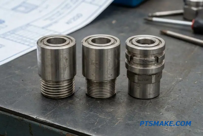
At PTSMAKE, we leverage CNC machining to produce custom end fittings. This means we can machine virtually any thread type—be it metric, SAE, or BSP—onto a standard coupling body. This eliminates the need for adapters, which introduce additional potential leak points and complexity.
Beyond Threads: Hose Connections
The connection to the hose is just as important. For applications like liquid cooling connectors in data centers, a secure connection is non-negotiable. Locking hose barbs provide excellent grip and security, while push-lock fittings offer quick, tool-free assembly for lower-pressure systems. For high-pressure hydraulic applications, ferrule-style connections are the standard.
Error-Proofing Assembly
To prevent misconnections in complex systems, we can implement physical and visual safeguards. After discussing with clients, we find that keyed quick disconnect couplings, which only allow matched pairs to connect, are highly effective. We also offer color-coding options on components for easy visual identification, simplifying assembly and maintenance. This helps prevent costly Creep relaxation16 in seals due to improper connections.
Selecting the correct thread and end fitting is vital for system integrity. Precision CNC machining provides the flexibility to create reliable, custom connections for any application, eliminating adapters and preventing leaks. This ensures components integrate seamlessly, avoiding costly failures and downtime.
Testing and Validation — Helium Leak Test, Pressure Test, and Cycle Life Verification
When sourcing Quick Disconnect Couplings, you must demand rigorous validation. Not all testing is created equal. The right tests ensure reliability and safety in your application. I always advise clients to specify a core set of verifications before committing to a production run.
Key Validation Tests
These tests provide a comprehensive picture of a coupling’s performance. They confirm everything from microscopic seal integrity to long-term mechanical endurance. Relying on basic checks is a risk not worth taking for critical systems.
| Test Type | Verification Goal |
|---|---|
| Helium Leak Test | Detects minute leaks (to 10⁻⁶ mbar·L/s) |
| Hydrostatic Pressure Test | Confirms structural integrity (to 1.5x rated pressure) |
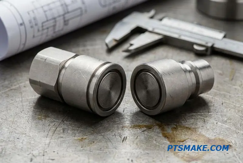
| Cycle Life Test | Verifies durability (>10,000 mate/demate cycles) |
| Burst Pressure Test | Determines ultimate failure pressure point |
Raising the Bar on Testing Standards
Some suppliers treat comprehensive testing as a premium service. I disagree. Companies like Danfoss perform a helium leak test on every coupling, which should be the industry standard. Demanding this level of validation isn’t unreasonable; it’s essential for performance-critical applications.
From Machining to Pass Rate
Consistent test results start with consistent manufacturing. At PTSMAKE, our precision CNC machining ensures that critical sealing surfaces and interlocking components meet exact specifications on every part. This directly translates to higher pass rates on sensitive helium leak tests and pressure tests.
This process eliminates microscopic variations that can cause failures. It’s why a robust coupling cycle life test often succeeds; the parts wear predictably because they were made identically. Hydrostatic testing17 confirms that this precision creates a structurally sound assembly capable of handling pressures well beyond its operational rating.
| Test Protocol | Standard Supplier | High-Reliability Supplier |
|---|---|---|
| Leak Test | Batch sample pressure decay | 100% helium mass spectrometry |
| Pressure Test | To rated pressure | 1.5x rated pressure (hydrostatic) |
| Cycle Life | Not typically performed | Certified >10,000 cycles |
Rigorous validation, including helium leak, pressure, and cycle tests, is essential for reliable Quick Disconnect Couplings. Consistent manufacturing, like precision CNC machining, is the foundation for meeting these demanding standards and ensuring long-term performance in the field.
Prototype to Production — How CNC Machining Scales Without the Tooling Trap
The biggest hurdle in scaling from a prototype to production is often tooling. For components like Quick Disconnect Couplings, traditional methods lock you into a design. Any change means expensive mold rework and long delays. This is what I call the tooling trap.
CNC machining completely sidesteps this issue. There is no hard tooling required. A design revision only costs a few minutes of programming time, not weeks of waiting for a new mold. This agility is a significant advantage for hardware development.
CNC vs. Traditional Tooling Timelines
| Stage | CNC Machining | Casting/Forging |
|---|---|---|
| Initial Tooling | None (0 weeks) | 8-12 weeks |
| Design Revision | 1-2 hours (programming) | 2-4 weeks (rework) |
| First Articles | 1-2 weeks | 10-16 weeks |
This shows the clear time benefit. You can get parts for testing much faster.
The path from prototype to production becomes a simple, linear process with CNC. At PTSMAKE, we often start with a quick disconnect coupling prototype run of 10-50 units. Once you validate the design, scaling up is seamless. The same program and setup are used for 1,000 pieces.
The only variables that change are material cost and machine runtime. This makes scalable CNC manufacturing for couplings predictable and financially manageable. There are no sudden, large capital expenditures for tooling as production volumes increase. This is especially valuable for custom coupling low volume production where initial investment needs to be low.
Scalability Factors: CNC vs. Casting
| Factor | CNC Machining | Casting/Forging |
|---|---|---|
| Initial Investment | Low (no tooling) | High (mold cost) |
| Per-Part Cost (Low Vol.) | Moderate | Very High |
| Per-Part Cost (High Vol.) | Stable | Decreases |
| Design Flexibility | High | Very Low |
Understanding material behavior, like Work hardening18, is critical during this process. For certain stainless steels or nickel alloys used in couplings, the machining process itself can alter the material’s surface properties, which we must control for consistent performance across the entire production run.
CNC machining offers a direct, tool-free path from prototype to production. This approach saves significant time and upfront investment, making it ideal for validating designs and scaling the manufacturing of custom Quick Disconnect Couplings without financial risk or long delays.
Total Cost of Ownership — Why a $15 Precision-Machined Coupling Beats a $8 Cast One
The upfront cost of a component is often misleading. A cast coupling might seem like a smart saving, but this initial view ignores the total cost of ownership (TCO). The real evaluation comes from performance, reliability, and the consequences of failure over the product’s entire lifecycle.
Initial Price vs. Lifetime Value
Focusing only on the purchase price is a common mistake. A precision-machined part offers superior durability and performance that prevents far greater expenses down the line. True cost-effectiveness is measured over years of flawless operation, not in the first transaction.
Comparing Upfront Costs to Potential Failure Costs
The small premium paid for a machined part is an investment in stability. A failure in a critical system, like a data center’s liquid cooling, can trigger costs that dwarf the initial savings.
| Cost Factor | $8 Cast Coupling | $15 Machined Coupling |
|---|---|---|
| Initial Purchase | Low | Higher |
| Risk of Leakage | High | Extremely Low |
| Potential Downtime | High | Minimal |
| Lifecycle Cost | Very High | Low |
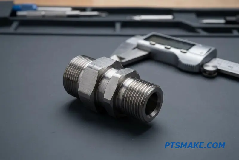
Choosing a lower-cost cast coupling for a critical application like a data center’s liquid cooling system introduces significant risk. These components are prone to porosity and internal defects. A single failure can lead to coolant leaks, damaging server hardware that costs tens of thousands of dollars.
The Domino Effect of a Single Failure
Downtime in a data center is catastrophic, costing businesses enormous sums for every minute of outage. This unplanned maintenance, coupled with hardware replacement costs, reveals the true expense of an unreliable component. The brand’s reputation for dependability is also on the line.
Lifecycle and Reliability Comparison
Precision CNC-machined quick disconnect couplings provide a solution. Our tests show they last 3 to 5 times longer than cast alternatives. The precise manufacturing process eliminates material imperfections that cause Stress concentration19, ensuring a secure, leak-free connection over countless cycles. This reliability translates directly into a better return on investment.
| Feature | Cast Coupling | Machined Coupling |
|---|---|---|
| Manufacturing Process | Molten metal in a mold | Solid block machining |
| Material Integrity | Prone to voids, porosity | Uniform, dense material |
| Expected Cycle Life | 1x | 3x – 5x |
| Failure Predictability | Low | High (Predictable Wear) |
At PTSMAKE, we focus on delivering this long-term value. Investing in a machined fluid connector reduces coolant loss, eliminates unplanned repairs, and protects your most valuable assets.
A higher upfront investment in a precision-machined coupling provides a significantly lower total cost of ownership. It prevents catastrophic failures, costly downtime, and reputational damage, ensuring long-term reliability and peace of mind for critical systems like data centers.

Understanding tribology helps in designing durable couplings that prevent leaks in high-stakes data center environments. ↩
Understanding this concept helps in designing couplings that maintain consistent performance over thousands of cycles. ↩
This term is key to avoiding costly sourcing errors for critical data center components. ↩
Understanding this property is key for selecting materials in electronics cooling, preventing electrical discharge and component failure. ↩
Understanding this process helps prevent coupling failure when dissimilar metals are used in humid environments. ↩
Learn how this valve’s mechanics impact fluid spillage and system contamination in sensitive applications. ↩
Learn how this wear phenomenon affects component integrity in high-vibration applications. ↩
Understanding this principle helps you design more efficient fluid systems and select better components. ↩
Understanding the motion of mechanical parts helps design more efficient and reliable tool-free connectors. ↩
Learn how these microscopic surface peaks influence friction, wear, and lubrication. ↩
Learn how this metric directly impacts cooling efficiency and system design in thermal management applications. ↩
Discover how material choice in these seals impacts the long-term reliability and leak prevention of liquid cooling systems. ↩
Learn how this property impacts material choice in demanding thermal management applications. ↩
Explore how this symbolic language ensures parts meet precise form, fit, and function requirements. ↩
Learn how this standard ensures the material’s origin and quality are independently verified, crucial for high-stakes applications. ↩
Understanding this helps predict long-term seal performance and prevent connection failures. ↩
Learn how this test validates structural integrity under pressure in critical engineering applications. ↩
Learn how this effect influences material selection and machining strategy for durable parts. ↩
Understanding this concept helps in designing parts that better distribute loads and avoid premature failure. ↩