Why CNC Machining for Liquid Cooling Components Matters Now
AI GPUs now push past 1000W TDP. Data center racks hit 50+ kW. Air cooling can’t keep up, and one leaky cold plate can take down a $2M server rack overnight.
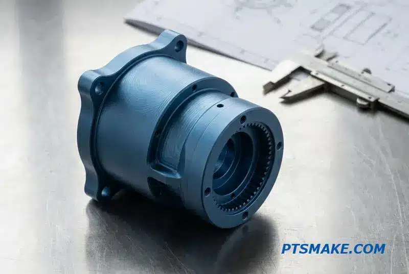
CNC machining is the dominant process for making liquid cooling components like cold plates, manifolds, and fluid connectors because it delivers tight sealing tolerances, complex flow channels, and zero tooling cost — all critical for reliable thermal management in modern high-power electronics.
I’ve spent the last few years helping thermal engineers move from prototype to production on liquid cooling projects. Below, I’ll walk you through what really matters — from channel design to O-ring grooves to pressure testing.
Why CNC Machining Took Over Liquid Cooling Component Manufacturing
Modern electronics are generating immense heat. We see AI GPUs now exceeding 1000W TDP and data center racks pushing past 50 kW. Air cooling simply can’t keep up, making the shift to liquid cooling essential. This is where CNC machining became the dominant manufacturing process for these critical components.
Unlocking Complex Designs
CNC machining allows for the creation of intricate internal geometries like serpentine paths and microchannels. These designs are vital for maximizing thermal transfer, and CNC machining makes them possible without the high initial tooling costs associated with other methods, especially for prototyping and small batches.
The Importance of Precision and Materials
Tight tolerances on sealing surfaces are non-negotiable to prevent leaks. Our CNC machining services consistently achieve this. Furthermore, material flexibility is a significant advantage, allowing us to use the best material for the job.
| Feature | CNC Machining | Casting |
|---|---|---|
| Tooling Cost | Low to None | High |
| Precision | Very High | Low to Medium |
| Complexity | High | Medium |
| Lead Time | Short | Long |
CNC machining for liquid cooling is not just about cutting metal; it’s about enabling advanced thermal designs. It directly bridges the gap between a thermal engineer’s simulation and a physical part that performs reliably. This direct translation from digital model to finished component is key.
Achieving Optimal Fluid Dynamics
The performance of a liquid cooling system depends heavily on the internal flow path. We use CNC milling to create microchannels that maximize the surface area for heat exchange. Unlike other methods, this process ensures the channels are clean and dimensionally accurate, which is critical for efficient performance.
Material Integrity and Thermal Expansion
Material choice is also crucial. While copper offers superior thermal conductivity, aluminum provides a lighter, more cost-effective solution. The manufacturing process must not compromise the material’s properties. Our process also carefully considers the Coefficient of Thermal Expansion1 when mating different materials to prevent stress-induced failures.
| Material | Thermal Conductivity (W/mK) | Key Benefit |
|---|---|---|
| Copper C110 | ~385 | Maximum Performance |
| Aluminum 6061 | ~167 | Cost-Effective & Lightweight |
At PTSMAKE, we frequently work with engineers to select the optimal material based on thermal requirements and budget, ensuring the final part meets all specifications without compromise.
CNC machining has become the industry standard for high-performance liquid cooling components. Its ability to produce complex internal geometries with high precision and material flexibility makes it the only practical choice for meeting the demands of modern electronics.
Cold Plate Types and When Each Needs CNC Machining
Choosing the right cold plate involves balancing performance and cost. Not every design requires extensive CNC machining. The level of precision needed often dictates the manufacturing approach. Let’s break down the main types and where CNC becomes essential for performance.
Tube-Embedded vs. Machined Channel
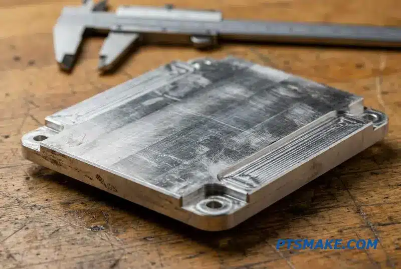
Tube-embedded plates are cost-effective for moderate heat loads. We use CNC to machine precise grooves for the copper tubes, ensuring optimal thermal contact. Machined channel plates, however, have the fluid path milled directly into the metal for more complex designs and better performance.
Microchannel and Brazed Assemblies
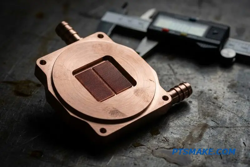
For high-power applications, microchannel plates feature tiny, CNC-milled fins. Vacuum-brazed assemblies also rely on CNC to create intricate fin stacks. Both methods provide maximum surface area for heat dissipation but involve more intensive machining processes.
The decision to use a specific type of CNC cold plate depends entirely on the thermal requirements. Each construction method offers a different level of performance, directly tied to the complexity of its CNC machining process. Understanding this link is key to efficient product design.
Tube-Embedded and Machined Channel Details
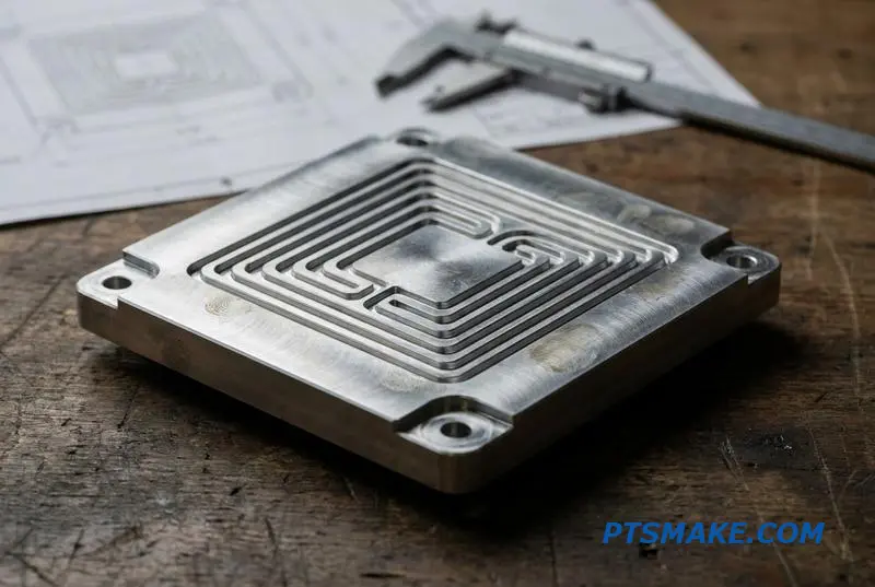
With tube-embedded plates, CNC machining is limited to creating the groove. The tube’s surface quality is the primary factor. For machined channel plates, our CNC Machining Services mill the entire serpentine or parallel path, creating a seamless fluid channel after a cover is sealed.
Advanced Thermal Solutions
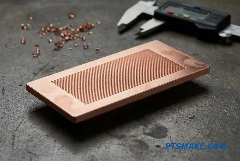
Microchannel plates push thermal performance to its limits. We machine fins as narrow as 200-500 microns. Vacuum-brazed plate-fin assemblies involve stacking and joining CNC-machined fins in a furnace, a process known as Brazing2. This creates a strong, leak-proof, and highly efficient thermal unit.
| Application | Recommended Cold Plate | CNC Involvement Level |
|---|---|---|
| High-Power IGBT | Machined Channel / Brazed | High |
| CPU/GPU | Microchannel | Very High |
| Laser Diode | Machined Channel | High |
| EV Battery | Tube-Embedded | Medium |
The right cold plate choice balances thermal performance with manufacturing complexity. High-heat applications demand intricate designs, making precision CNC machining essential for reliability and efficiency. This ensures components operate within safe temperature limits.
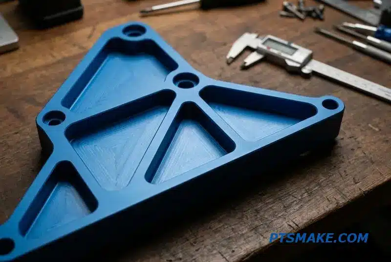
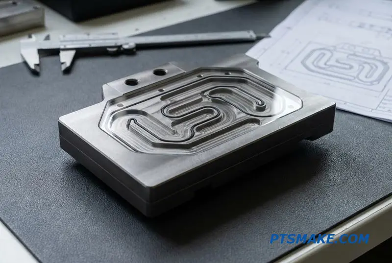
Flow Channel Design — What CNC Machining Makes Possible That Other Methods Cannot
The Challenge of Thermal Management
Effective thermal management often comes down to the design of internal flow channels. The goal is to maximize heat transfer while managing pressure drop. However, traditional manufacturing methods impose significant constraints, limiting how efficiently we can move fluid to remove heat.
Limitations of Traditional Methods
Methods like extrusion or stamping are cost-effective for simple, straight channels but struggle with complexity. Die casting offers more options but involves high tooling costs and design limitations like draft angles. These restrictions can compromise thermal performance from the start.
| Manufacturing Method | Primary Advantage | Key Design Constraint |
|---|---|---|
| Extrusion | Low cost for long parts | Straight, uniform profiles only |
| Stamping | High volume, low piece price | Limited depth and simple shapes |
| Die Casting | Complex external shapes | Requires draft angles; high MOQ |
The CNC Machining Advantage
CNC machining removes these barriers. It allows for the creation of intricate, optimized flow paths directly from a digital model. This freedom enables engineers to design for performance first, rather than being limited by manufacturing constraints. Our CNC Machining Services provide this exact capability.
Unlocking Design Freedom with CNC
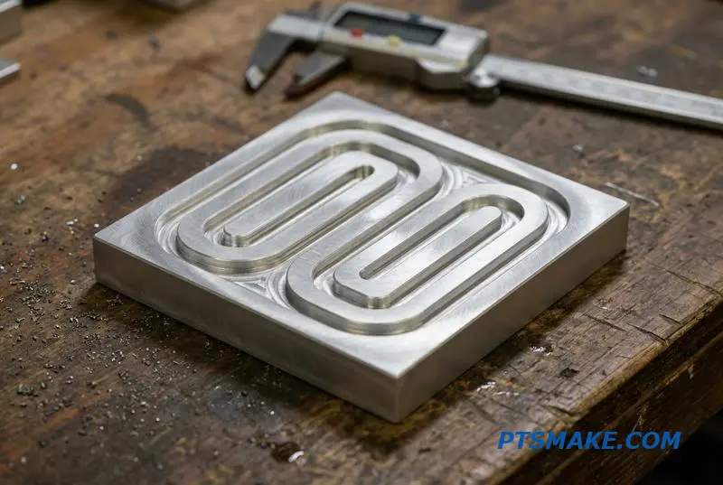
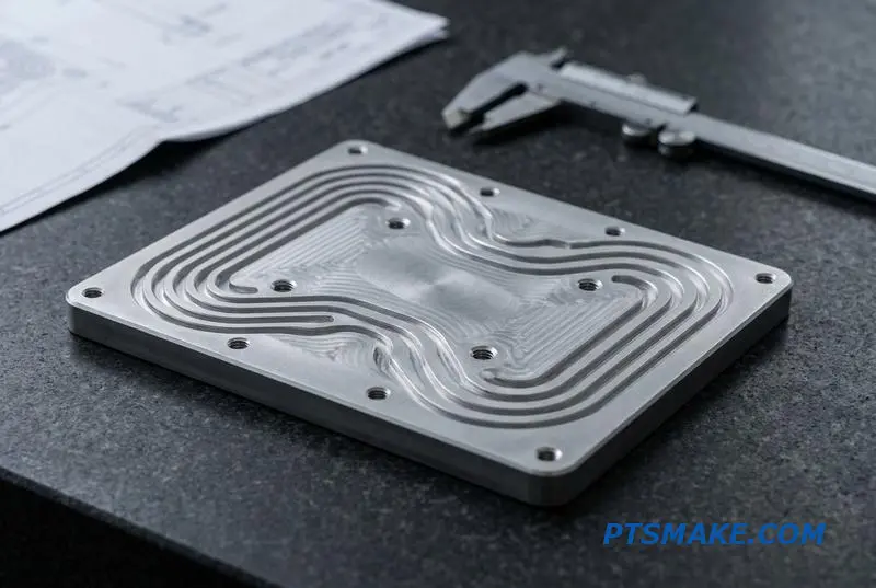
CNC machining provides unparalleled freedom for creating coolant flow paths. Unlike extrusion, which is confined to straight, prismatic shapes, CNC can produce serpentine channels with full 180-degree turns. This maximizes the channel length within a given area for better heat absorption.
Complex Geometries Made Simple
Stamping limits channel depth and requires draft angles, while die casting requires expensive molds and high minimum orders. CNC machining bypasses these issues entirely. We can mill pin-fin arrays with variable density, create asymmetric inlet plenums, or even produce tapered channels that ensure uniform flow distribution.
Engineering for Performance
This precise control over geometry directly impacts the fluid dynamics, a key factor in thermal performance. By manipulating channel width and path, we can influence the Reynolds number3, which governs the transition between laminar and turbulent flow. This helps balance thermal resistance against pressure drop.
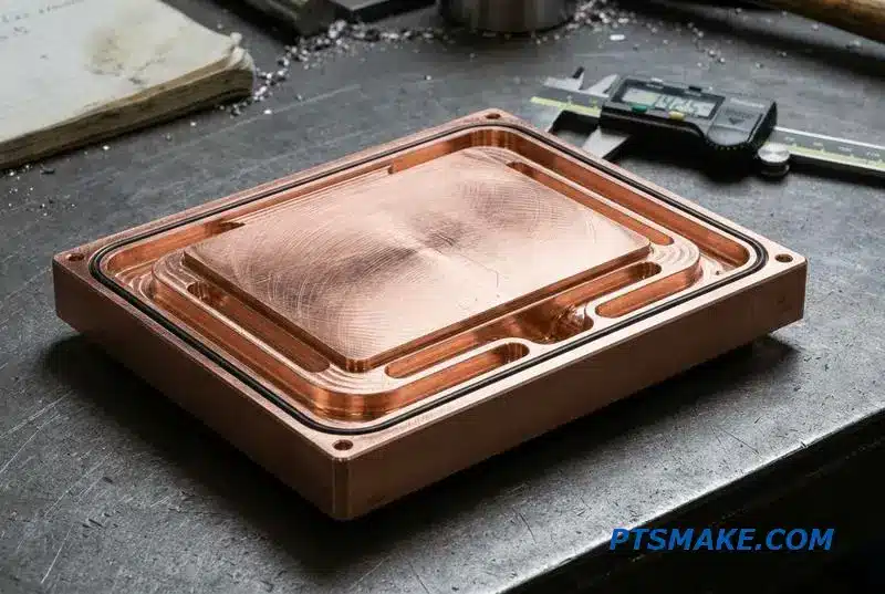
For instance, we recently produced a 200x200mm CNC flow channel cold plate for a client. It featured a 5-pass serpentine channel, 3mm wide and 4mm deep, milled in a single setup on one of our 3-axis machines, achieving optimal thermal contact.
CNC machining unlocks superior thermal performance by enabling complex flow channel geometries. These optimized designs, impossible with methods like extrusion or casting, allow engineers to precisely control fluid dynamics and maximize heat transfer efficiency in critical components.
Microchannel Cold Plates — CNC Machining’s Precision Frontier
When dealing with high-heat-flux applications, standard cooling solutions fall short. I’ve seen this in projects involving laser diodes and SiC power modules. This is where microchannel cold plates come in, offering superior thermal performance by maximizing the surface area for heat transfer.
The Rise of High-Density Cooling
The demand for compact, powerful electronics pushes thermal limits. Traditional cold plates can’t keep up. Microchannel designs, however, provide an effective path for dissipating intense, localized heat, ensuring reliability and performance for sensitive components. CNC machining services are key to creating these intricate structures.
Key Applications
These specialized components are critical across several advanced industries. Their ability to manage intense thermal loads is essential for device longevity and operational efficiency.
| Application | Key Thermal Challenge |
|---|---|
| Laser Diodes | Concentrated heat at the emitter |
| SiC Power Modules | High power density and switching losses |
| Concentrated Photovoltaics | Intense solar energy focused on a small cell |
Manufacturing Microchannels
Creating these tiny, precise channels requires specialized techniques. While several options exist, they each present a different balance of cost, speed, and capability. At PTSMAKE, we focus on what provides the most value from prototype to production for our partners.
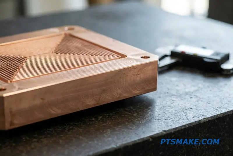
CNC Micro-Milling: The Sweet Spot
For most applications, CNC micro-milling is the ideal solution. It offers design flexibility with near-zero tooling cost, allowing for rapid iteration. We can machine slots from 0.2mm to 1.0mm wide with aspect ratios up to 10:1, turning designs into hardware in days.
Alternative Manufacturing Methods
Other methods have their place. Micro-EDM achieves finer details but is significantly slower. Chemical etching is fast for shallow features but lacks depth control. Deep Reactive-Ion Etching4, or DRIE, offers incredible precision but is typically reserved for silicon wafer fabrication due to its high cost.
| Method | Typical Use Case | Cost Profile |
|---|---|---|
| CNC Micro-Milling | Prototype to medium volume | Low to moderate |
| Micro-EDM | Ultra-fine features | High |
| Chemical Etching | Shallow, mass-produced channels | Low (at scale) |
| Silicon DRIE | Semiconductor-level precision | Very high |
Tooling and Machining Challenges
Working at this scale has its difficulties. Micro-endmills under 0.5mm are fragile and require precise control to prevent breakage. Effective cooling is also critical, which is why we rely on high-pressure, through-spindle coolant systems to clear chips and maintain a clean surface finish inside the narrow slots.
Microchannel cold plates are essential for high-heat-flux applications. While various manufacturing methods exist, CNC micro-milling offers the best balance of precision, cost, and speed for prototyping and medium-volume production, making it a highly practical choice for advanced thermal management.
Materials for CNC-Machined Liquid Cooling Components
Choosing the right material for liquid cooling components is a critical first step. Your decision impacts thermal performance, cost, and manufacturing complexity. The best choice always depends on the specific application’s demands and budget constraints.
The Most Common Choices
Aluminum 6061-T6 is often the default choice. It offers good thermal conductivity and is easy to machine, making it a cost-effective all-arounder. For higher performance, Copper C110 is the top contender due to its superior thermal properties.
Quick Comparison
| Material | Thermal Conductivity (W/mK) | Key Feature |
|---|---|---|
| Aluminum 6061-T6 | 167 | Best all-around value |
| Copper C110 | 395 | Highest thermal performance |
| Stainless Steel 316L | 16 | Excellent corrosion resistance |
This balance between performance and cost is a constant theme in providing CNC Machining Services for thermal management.
While aluminum and copper are primary choices, specialized applications require different materials. For example, we use stainless steel 316L for fittings in automotive glycol loops where corrosion resistance is more important than thermal conductivity. Titanium Grade 2 is for highly corrosive industrial environments.
Aluminum vs. Copper Cold Plates
Clients often ask if copper’s performance justifies its cost. Copper offers nearly 2.5 times the thermal conductivity of 6061 aluminum. However, it can also be 3-5 times more expensive in both material and machining costs. Copper is justified for applications where every degree matters, such as high-power CPUs or lasers.
Advanced Considerations
For mixed-metal loops, nickel-plated aluminum is a great solution. The plating prevents Galvanic corrosion5, which can occur when different metals are in contact with an electrolyte. Our CNC Machining Services are tailored to handle these specific material and finishing requirements effectively.
Decision-Making Matrix
| Application | Thermal Need | Recommended Material | CNC Machinability | Relative Cost |
|---|---|---|---|---|
| Consumer PC | Medium | Aluminum 6061-T6 | Excellent | Low |
| High-End Server | High | Copper C110 | Fair | High |
| Automotive Loop | Low (Connectors) | Stainless Steel 316L | Good | Medium |
| Medical Device | High (Purity) | Copper C101 OFHC | Fair | Very High |
Selecting the ideal material is a crucial balance between thermal needs, machinability, corrosion resistance, and budget. For most projects, aluminum offers a great starting point, but copper is essential when maximum heat dissipation is the primary goal.
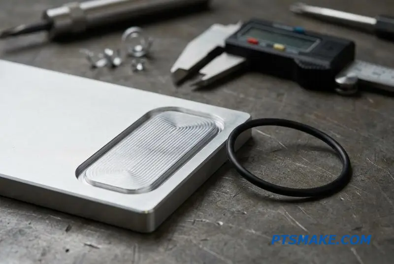
Sealing Precision — Why O-Ring Groove Tolerance Decides Whether Your Cold Plate Leaks
The most common failure in liquid cooling is leakage. This almost always happens at the sealing interface where an O-ring sits. The precision of the O-ring groove isn’t just a detail; it’s the single most important factor determining if your cold plate leaks under pressure.
Key Groove Design Principles
Success depends on controlling groove depth, surface finish, and wall perpendicularity. Even small deviations can compromise the seal. We focus on these details in our O-ring groove machining process because they prevent field failures before they ever happen.
Groove Type Comparison
| Feature | Dovetail Groove | Rectangular Groove |
|---|---|---|
| O-Ring Retention | Excellent | Good |
| Machining Cost | Higher | Lower |
| Common Use | High vibration | General purpose |
Why Manufacturing Method is Crucial
You can design the perfect groove, but the manufacturing method determines the final quality. Die casting, for example, often struggles to achieve the necessary tolerances and surface finish directly. The resulting grooves usually require a secondary machining operation to become reliable for sealing.
This is where precision CNC machining provides a clear advantage. We can machine grooves that meet specifications from the start.
A Case of Critical Failure
I recall a project where a client’s cold plates were failing at 8 bar. The groove depth was specified at 2.5mm, but a previous supplier produced them at 2.6mm. This tiny 0.1mm error reduced O-ring compression, allowing seal Extrusion6 and subsequent leakage.
This highlights how critical O-ring groove machining is. Below are the typical tolerances we work with, which our CNC machining services consistently achieve.
| Parameter | Typical Tolerance | Critical Application |
|---|---|---|
| Groove Depth | ±0.05 mm | ±0.025 mm |
| Surface Finish (Ra) | ≤ 0.8 µm | ≤ 0.4 µm |
| Wall Perpendicularity | Within 0.1° | Within 0.05° |
By holding these tight tolerances, we ensure every part creates a perfect, lasting seal.
A precise O-ring groove is non-negotiable for reliable liquid cooling. Deviations in depth, finish, or perpendicularity lead to leaks. Precision O-ring groove machining is not an expense but an investment in product reliability, directly preventing costly field failures and ensuring long-term performance.
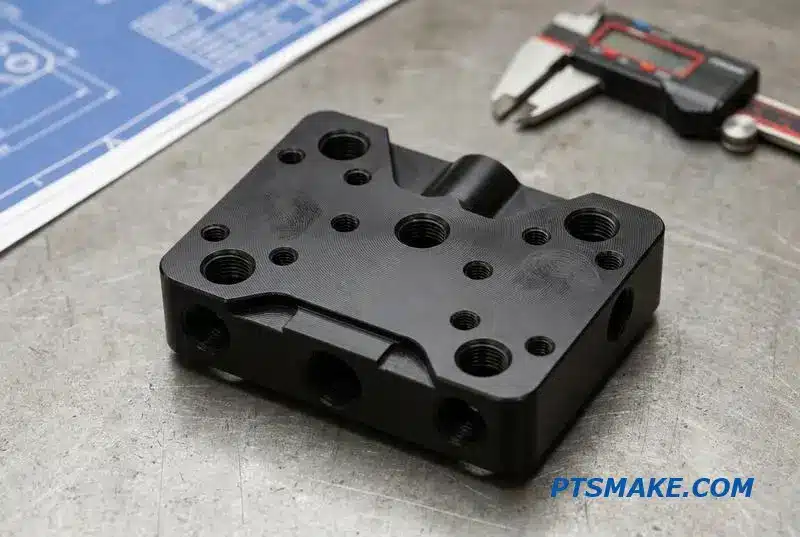
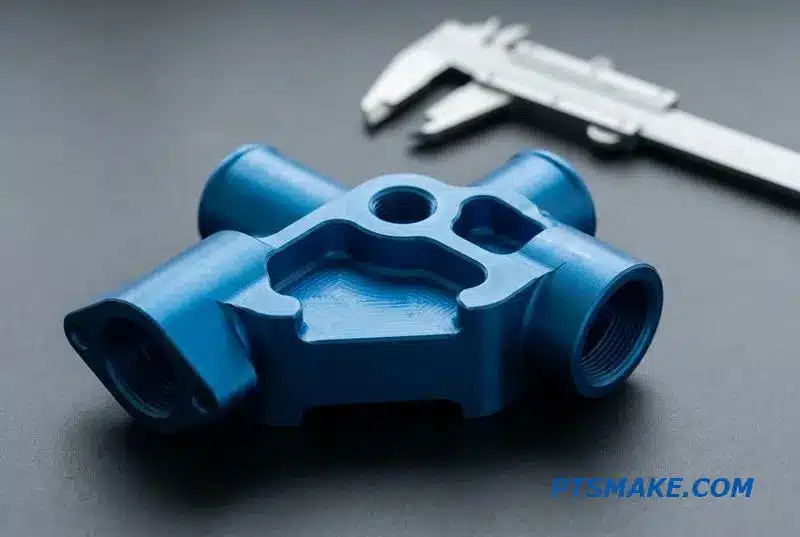
Manifold Machining — Connecting Multiple Cold Plates Without Pressure Imbalance
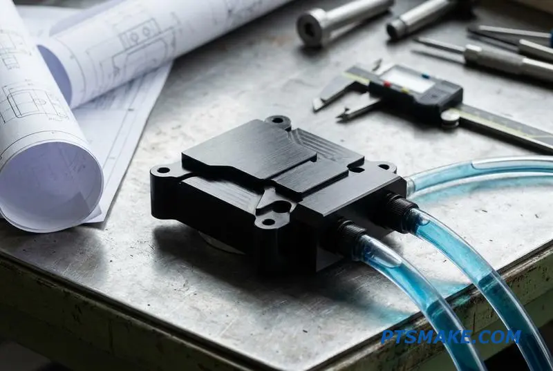
Liquid cooling manifolds are central to modern Coolant Distribution Units (CDU) and rack-level systems. Their job is to distribute coolant evenly to multiple cold plates. Achieving this without pressure imbalance or leaks is the main challenge we face in manufacturing them.
The design demands absolute precision. This includes creating complex internal flow passages and multiple threaded ports at exact locations. Every connection must be perfectly sealed. Our approach using advanced CNC machining services ensures every manifold meets these strict requirements for optimal performance.
The Role in System Integrity
Manifolds act as the circulatory system for high-density electronics. Any failure, like a leak or imbalanced flow, can lead to catastrophic hardware damage. That’s why machining them from a solid billet is often the most reliable method.
Precision Machining for Flawless Performance
Creating a reliable manifold requires a multi-step CNC machining process. For complex multi-port designs, we use 4-axis or 5-axis milling to machine the external features and port locations with high precision. This is critical for ensuring proper alignment in the final assembly.
Crafting Internal Passages
Long internal flow passages are created using specialized techniques. After our tests, we found BTA deep-hole drilling7 is ideal for maintaining straightness and a smooth finish over long distances, which is essential for predictable fluid dynamics. Passages are then carefully plugged to create a sealed, continuous flow path.
Port Creation: Thread Milling vs. Tapping
For port threads, thread milling is superior to tapping. It offers much better control over positional tolerance and thread quality. This precision is non-negotiable for ensuring leak-free connections across every port.
| Feature | Thread Milling | Tapping |
|---|---|---|
| Positional Accuracy | High | Moderate |
| Thread Quality | Excellent | Good |
| Tooling Cost | Higher | Lower |
| Process Control | Superior | Standard |
For example, we machined a 12-port distribution manifold for an AI server cabinet from a single 6061 aluminum billet. This design for CNC manifold liquid cooling eliminated 24 potential leak points that would have existed with traditional tube fittings.
Precision CNC machining is the key to producing reliable, leak-free liquid cooling manifolds. This manufacturing approach ensures balanced flow and enhances overall system integrity, which is critical for high-performance computing applications and prevents costly failures.
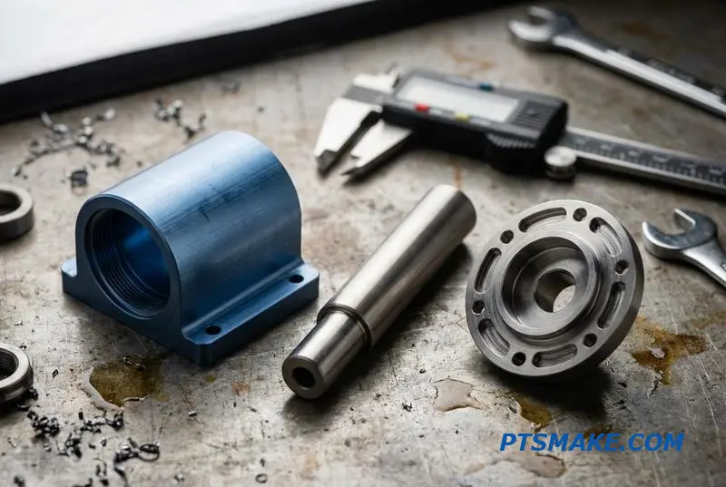
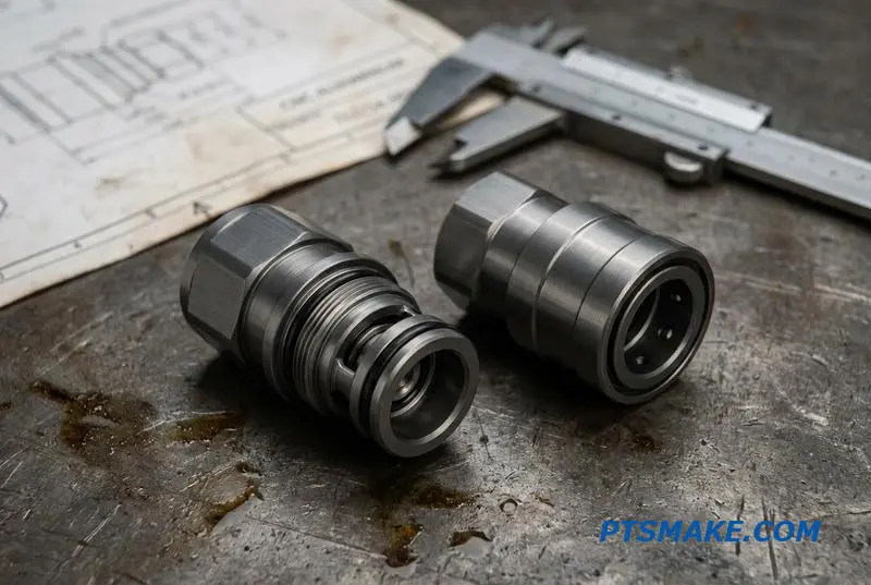
Fluid Connectors and Quick-Disconnect Couplings — Swiss Turning at Its Best
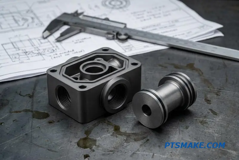
In liquid cooling systems, performance hinges on the smallest components. Quick-disconnect (QD) couplings, fittings, and valves are where Swiss-type CNC lathes truly excel. Their ability to produce highly concentric parts with exceptional surface finishes is critical for leak-proof performance and reliability.
Key Components in Liquid Cooling
These small, cylindrical parts are the backbone of any fluid loop. They must be machined perfectly to prevent costly failures. At PTSMAKE, we focus on achieving this precision from the very first part.
Fitting Types and Functions
Different fittings serve specific roles within a cooling loop. Each requires a unique manufacturing approach to ensure a secure connection.
| Fitting Type | Primary Use | Machining Focus |
|---|---|---|
| Barbed Fittings | Flexible tubing | Sharp, consistent barbs |
| Compression Fittings | Rigid tubing | Precise thread & ferrule seat |
| QD Couplings | Frequent connection | Sealing cone & valve seats |
This is where Swiss turning demonstrates its superiority for manufacturing liquid cooling connectors.
Swiss turning is not just a preference for these components; it’s a necessity. The process inherently supports the part along its length, minimizing deflection and vibration. This is crucial for achieving the tight tolerances needed for reliable fluid connectors.
Precision Sealing Surfaces
The most critical feature of any coupling is its ability to create a perfect seal. For sealing cones and valve seats, we often need a surface finish of Ra ≤ 0.2 μm. Anything less compromises the seal, leading to leaks over time, especially under pressure.
Threads and Grooves
For QD coupling threads, thread rolling is often superior to single-point threading. It creates stronger, smoother threads, which improves durability over many connection cycles. Turning O-ring grooves on diameters under 10mm also demands extreme stability to avoid tool chatter and ensure groove geometry is perfect for seal compression. True Concentricity8 is key here.
Case Study: Automotive QD Coupling
We recently produced a QD coupling body for an automotive battery cooling loop. The part was machined from 316L stainless steel. A key challenge was machining a 60-degree sealing cone held to a positional tolerance of ±0.01mm. Our Swiss CNC machining services delivered the required precision consistently across the production run.
Swiss turning is the ideal method for producing high-performance liquid cooling connectors. Its ability to maintain tight tolerances, achieve fine surface finishes, and ensure concentricity is essential for creating the leak-proof, reliable components required in critical systems like automotive and electronics cooling.
Pressure Testing Requirements for CNC-Machined Cooling Components
When manufacturing CNC-machined cooling components, pressure testing is not optional. It is a critical step to guarantee leak-free performance and operational safety. A failed part can lead to catastrophic system damage, making robust testing a cornerstone of reliability for any project I oversee.
Key Testing Parameters
Engineers must clearly define the test pressure, typically 1.5 times the maximum operating pressure, and a hold time. This duration usually ranges from 30 seconds to several minutes. The specific time depends on the application’s criticality and the materials involved in the design.
Common Testing Methods
Different applications require different approaches. Based on our experience working with clients at PTSMAKE, a clear understanding of each test type is crucial for specifying the right requirements.
| Test Type | Primary Purpose | Common Application |
|---|---|---|
| Hydrostatic | Leak and strength validation | Liquid-filled cold plates |
| Pneumatic | High-sensitivity leak detection | Vacuum-brazed assemblies |
| Burst | Design margin verification | New product validation |
Advanced Testing Protocols
Beyond standard checks, we often see combined tests. For instance, thermal cycling combined with pressure cycling simulates real-world operating conditions more accurately. This process exposes weaknesses that might not appear under static pressure alone, ensuring a more robust and reliable final product.
For vacuum-brazed cold plates, pneumatic testing with a helium leak detector is standard. It offers much higher sensitivity than hydrostatic tests for detecting micro-leaks. Burst pressure testing, while destructive, is invaluable for validating the ultimate design margin during the critical prototyping phase.
How Machining Quality Affects Outcomes
The quality of our CNC Machining Services directly impacts test results. Inconsistent wall thickness, a common issue with poor tool path programming, creates areas of high stress concentration9. These areas are the most likely points of failure when a component is placed under pressure.
A smooth surface finish in O-ring grooves is equally vital. Any minor imperfection or tool mark can create a leak path, causing a part to fail a test. Precision machining eliminates these risks and ensures a perfect seal. This attention to detail is fundamental to successful liquid cooling component testing.
| Criteria | Pass Condition | Fail Condition |
|---|---|---|
| Pressure Drop | No observable drop during hold time | Any pressure loss below specified tolerance |
| Visual Inspection | No leaks, cracks, or permanent deformation | Any visible fluid leakage or material yielding |
| Leak Rate (Pneumatic) | Below the maximum specified rate | Exceeds the helium leak rate threshold |
Specifying the correct liquid cooling component testing protocols is essential. These tests will only succeed if the underlying CNC machining quality is high. Precision in manufacturing directly ensures reliability under pressure, preventing costly failures for our clients in the field.
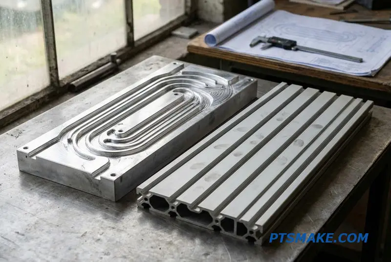
CNC Machining vs. Extrusion for Cold Plate Base Plates
Choosing the right manufacturing method for cold plate base plates is a critical decision. The choice between full CNC machining and extrusion with secondary machining hinges on volume, design complexity, and lead time. Each approach has distinct advantages that I’ve seen play out on various projects.
Full CNC Machining Advantages
With our CNC machining services, you get unlimited design freedom. Complex, non-linear fluid channels are just as feasible as simple straight ones. Design changes are easy and cost-effective, as there is no tooling investment. This method also allows integrating mounting features and ports in a single setup.
Extrusion with Secondary CNC Advantages
Extrusion is ideal for high-volume production of cold plates with straight channel designs. The initial die cost is significant, but the per-unit price drops dramatically as quantities increase. This makes it a cost-effective solution for mass production where design is finalized.
| Feature | Full CNC Machining | Extrusion + Secondary CNC |
|---|---|---|
| Geometry | Unlimited complexity | Straight channels only |
| Lead Time | Short (no tooling) | Long (6-8 week die lead time) |
| Initial Cost | Zero tooling cost | High die cost |
| Unit Cost | Higher at high volume | Lower at high volume |
| Minimum Qty | None | High (to offset die cost) |
Engineers often ask me about the crossover point where one method becomes more economical than the other. This decision is rarely black and white; it’s a strategic choice based on your project’s lifecycle, budget, and performance requirements.
The Breakeven Analysis
The primary factor is the breakeven volume. For extrusion, the high upfront cost of the die must be amortized over the production run. This makes low-volume runs of 100 pieces very expensive. Full CNC machining avoids this tooling cost entirely, making it the default for prototyping and low-volume production.
Based on our analysis with clients, the breakeven point where extrusion plus secondary CNC becomes cheaper is typically between 500 and 2,000 units. The exact number depends on the plate’s size and the complexity of the secondary machining operations. Complex features like o-ring grooves or intricate porting can push the breakeven volume higher. It’s also important to consider the material properties, as the extrusion process can sometimes cause issues like Die swell10, which may affect final tolerances.
A Decision Framework for Engineers
Here is a simple framework to guide your choice between CNC vs extruded cold plate manufacturing methods.
| Scenario | Recommended Method | Rationale |
|---|---|---|
| Prototype / < 500 units | Full CNC Machining | No tooling cost, design flexibility, fast turnaround. |
| High Volume / > 2000 units | Extrusion + Secondary CNC | Lower per-unit cost significantly outweighs die cost. |
| Complex Fluid Path | Full CNC Machining | Extrusion cannot create non-linear or complex channels. |
| Uncertain Design | Full CNC Machining | Allows for inexpensive design iterations. |
For prototypes and low-volume production, full CNC machining offers unmatched flexibility and speed. As your production scales and the design stabilizes, extrusion with secondary CNC machining becomes the more cost-effective solution for simple, straight-channel designs. The choice ultimately balances cost, volume, and design complexity.
Flatness Specification for Cold Plate Mating Surfaces — What’s Actually Achievable
Flatness is a critical dimension on cold plate drawings, but it is also one of the most frequently over-specified. Understanding what is practically achievable with CNC machining services helps balance performance and cost. For most applications, we can achieve standard flatness without secondary operations.
Standard vs. Precision Flatness
Standard machining delivers excellent results for general-purpose cooling needs. However, more demanding applications with high heat flux require tighter control. This involves additional steps like stress relieving the material before the final cut to ensure stability and precision.
| Tier | Flatness (per 300mm) | Notes |
|---|---|---|
| Standard | 0.05 mm / 0.002 in | Achieved with standard CNC milling practices. |
| Precision | 0.02 mm / 0.0008 in | Requires stress-relief and optimized fixturing. |
| Ultra-Precision | 0.005 mm / 0.0002 in | Requires post-machining lapping. |
The Cost and Performance Trade-Off
The primary goal of a flat cold plate surface is to minimize the thickness of the Thermal Interface Material (TIM). A thinner TIM layer results in lower thermal resistance and better heat transfer. However, the pursuit of extreme flatness has diminishing returns.
Impact on Machining Costs
Achieving a tolerance tighter than 0.02 mm, especially on larger plates, significantly increases costs. It often requires multiple machining setups, a dedicated stress relief cycle, and temperature-controlled finishing passes. For the highest precision, such as surfaces for IGBT modules or laser diodes, post-machining Lapping11 is necessary.
Practical Specification Guide
Before finalizing a cold plate flatness tolerance, consider the TIM you plan to use. Specifying ±0.02mm flatness on a 400mm plate adds significant cost for minimal thermal benefit if you are using a 0.2mm thick thermal pad. At PTSMAKE, we help clients analyze this trade-off.
| TIM Thickness | Recommended Flatness | Rationale |
|---|---|---|
| > 0.15 mm | 0.05 mm | The TIM can fill larger gaps, making extreme flatness redundant. |
| 0.05 – 0.15 mm | 0.02 mm | A good balance between thermal performance and manufacturing cost. |
| < 0.05 mm | < 0.01 mm | Necessary for minimal thermal resistance with very thin interface materials. |
Specifying flatness requires balancing thermal goals with manufacturing costs. An extremely tight tolerance is only effective when paired with a thin thermal interface material. Always evaluate the entire thermal stack to avoid over-engineering and unnecessary expenses on your CNC machining services.
Thread Ports in Liquid Cooling Components — NPT vs G vs UNF
Selecting the right liquid cooling port threads is crucial for creating a reliable, leak-free system. The choice between NPT, G (BSPP), and UNF standards directly impacts sealing effectiveness, assembly, and regional compatibility. Each type has specific design and manufacturing considerations.
Key Differences at a Glance
Making an informed decision starts with understanding the fundamental differences in how these threads are designed to seal. This choice influences the entire component design, from wall thickness to surface finish requirements, which our CNC machining services expertly handle.
| Thread Type | Sealing Method | Geometry | Common Region |
|---|---|---|---|
| NPT | Thread interference (sealant required) | Tapered | North America |
| G (BSPP) | Gasket or O-ring on face | Parallel | Europe, Asia |
| UNF | O-ring in a groove (boss seal) | Parallel | High-Pressure (SAE J1926) |
Understanding these distinctions is the first step toward preventing costly leaks and ensuring long-term performance in your thermal management system.
Manufacturing and Design Rules
Beyond the basic type, how the thread is manufactured and integrated into the component design is critical for performance. The choice of manufacturing process can significantly affect the quality and reliability of the seal, especially for liquid cooling applications where leaks are unacceptable.
CNC Machining Considerations
For tapered NPT threads, we often recommend thread milling over tapping. Thread milling produces a superior surface finish on the thread flanks, which is essential for achieving a reliable seal with sealant. Tapping can sometimes tear the material, creating potential leak paths.
Single-point threading is another valuable technique, especially for non-standard sizes or profiles. This method gives us precise control over the thread geometry, ensuring it meets exact specifications for custom cooling solutions. It’s a core capability of our advanced CNC machining services.
Critical Design Parameters
When placing ports, maintaining adequate wall thickness between the port and an adjacent cooling channel is a key design rule. Our collaborative research with clients shows that a 3mm minimum is a safe guideline for aluminum parts at 5 bar pressure.
For G and UNF threads, the seal depends on an O-ring. The component face must be smooth and flat. More importantly, the port’s axis requires excellent Perpendicularity12 to the sealing face. This ensures the O-ring is compressed evenly, preventing leaks under pressure.
| Feature | NPT | G (BSPP) | UNF (O-Ring Boss) |
|---|---|---|---|
| Sealant/Tape | Required | Not required | Not required |
| O-Ring Groove | No | No (uses face seal) | Yes |
| Surface Finish | Critical on threads | Critical on face | Critical on face & groove |
| Perpendicularity | Less critical | Highly critical | Highly critical |
Choosing the correct liquid cooling port threads involves understanding the trade-offs between NPT, G, and UNF standards. Success depends on adhering to precise CNC machining practices and design rules like wall thickness and surface perpendicularity to ensure a robust, leak-proof cooling component.
When to Use 5-Axis CNC for Liquid Cooling Components
Five-axis CNC machining isn’t always required, but for certain complex liquid cooling parts, it’s the only practical solution. It allows us to create geometries that are impossible with traditional 3-axis machines, ensuring both performance and reliability in the final product.
Contoured and Angled Features
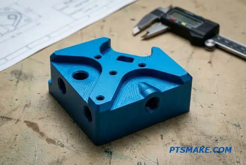
Many modern applications require cold plates to mate with non-flat surfaces like curved IGBT modules or cylindrical laser diodes. Five-axis machining allows us to create these contoured surfaces and drill angled ports on them in a single setup, maintaining critical positional accuracy.
Complex Internal Geometries
Internal features are where 5-axis CNC truly shines for liquid cooling. Manifold blocks often have intersecting passages that can only be reached from compound angles. This capability is essential for minimizing pressure drop and ensuring uniform coolant flow throughout the system.
Deciding between 3+2 and full simultaneous 5-axis machining is a critical step. From my experience, most 5-axis CNC liquid cooling components only require 3+2 positional machining. This approach offers most of the benefits without the higher programming and cycle time costs of full 5-axis.
3+2 vs. Full Simultaneous 5-Axis
Full simultaneous 5-axis is necessary for parts like impellers or components with continuously curving internal channels. For most manifolds and cold plates with angled features, 3+2 is the more efficient choice. It positions the part at a compound angle and then performs 3-axis machining operations.
The primary benefit here is setup reduction. A complex coolant distribution unit (CDU) manifold might need four or more separate setups on a 3-axis machine. Each new setup introduces a potential for error, leading to tolerance stack-up13.
| Feature Type | 3-Axis Setups | 5-Axis Setups | Key Advantage |
|---|---|---|---|
| Angled Ports on 5 Faces | 4-5 | 1 | Reduced tolerance stack-up |
| Contoured Cold Plate | 2-3 | 1 | Better surface continuity |
| Helical Battery Sleeve | 2 (with rotary) | 1 | Superior accuracy & finish |
At PTSMAKE, we guide clients on this choice to optimize cost and precision. By machining a part in a single setup, we ensure all features are perfectly aligned, which is critical for leak-proof and efficient thermal management systems. Our CNC machining services are built on this expertise.
Five-axis CNC is indispensable for complex liquid cooling parts. It enables the creation of intricate geometries, reduces setups, and minimizes tolerance stack-up. This leads to higher quality, more reliable components for demanding thermal management applications, making it a crucial manufacturing technology.
Lead Time Expectations for CNC Liquid Cooling Orders
Understanding the typical liquid cooling part lead time is crucial for project planning. A simple part isn’t the same as a complex assembly. At PTSMAKE, we break down timelines to provide clarity and help you manage expectations effectively from the start.
Standard Lead Time Estimates
Predictability is key in manufacturing. Here is a general guide based on part complexity. These estimates cover the process from drawing review and programming to final shipment.
Breakdown by Part Type
| Part Type | Estimated Lead Time |
|---|---|
| Simple Manifold/Connector | 5-7 Business Days |
| Standard Cold Plate | 7-14 Business Days |
| Complex Cold Plate (Microchannels) | 10-18 Business Days |
This framework provides a solid baseline for scheduling your initial builds.
Managing lead times involves more than just machining hours. Several factors can add to the timeline, and it’s important to account for them. Being aware of these variables helps prevent unexpected delays and keeps your project on track.
Factors Extending Lead Times
Certain processes and materials inherently require more time. For instance, parts needing vacuum brazing will have 5-7 days added for the brazing cycle and associated quality checks. This is a step we cannot rush if we want to ensure a perfect bond.
Material and Finishing Considerations
Special materials and finishes also impact the schedule. Copper, for example, machines slower than aluminum, so we typically add 3-5 days for copper cold plates. If you need a specific raw material size that isn’t in stock, procurement can add several days.
| Additional Process | Added Time |
|---|---|
| Vacuum Brazing Cycle | +5-7 Days |
| Copper Material Machining | +3-5 Days |
| Electroless Nickel Plating | +3 Days per Batch |
| Custom Tooling for Micro-Milling | +Variable |
Micro-milling complex channels often requires custom tooling, which has its own lead time. Furthermore, controlling Tool Deflection14 during this process is critical for accuracy, which may require slower machining speeds. Our CNC Machining Services are optimized to balance speed with precision.
Prototypes vs. Production
Interestingly, small prototype runs of 1-50 pieces can often be completed faster on a per-part basis than large production batches. This is largely due to the efficiency of CMM inspection; setting up and verifying the entire batch at once is quicker than inspecting parts individually over a longer production run.
Understanding typical lead times and potential delays from materials, custom tooling, and secondary processes is crucial. Proper planning ensures your liquid cooling project stays on schedule and meets the highest quality standards, a core part of our commitment at PTSMAKE.
Quality Control for CNC Liquid Cooling Parts — Beyond Dimensional Accuracy
When evaluating CNC-machined liquid cooling parts, relying solely on dimensional accuracy is a critical mistake. True quality control extends into functional performance. A part can be dimensionally perfect yet fail under operational pressure or temperature, leading to catastrophic system failures.
The Functional Testing Imperative
For any high-performance application, functional verification is non-negotiable. This means subjecting components to tests that simulate real-world conditions. Without this, you’re only getting half the quality picture. At PTSMAKE, our process integrates these crucial steps from the start.
Key Performance Verification Tests
We focus on a suite of tests designed to guarantee performance and reliability. These are the benchmarks a quality-conscious CNC machining services provider should meet.
| Test Type | Objective | Typical Specification |
|---|---|---|
| Flow Testing | Verify pressure drop | ±10% of CFD prediction |
| Helium Leak Testing | Ensure seal integrity | <1×10⁻⁶ mbar·L/s |
| Thermal Measurement | Validate heat dissipation | Matches design spec |
| Burst Pressure | Confirm structural safety | Varies by application |
These tests move beyond simple measurements to ensure the part works as intended.
Beyond the Caliper: Essential Quality Protocols
A reliable supplier must have robust protocols for liquid cooling part quality control. These protocols provide the data needed to confirm that every component not only fits but functions correctly. This approach minimizes risks for procurement managers and engineers.
Validating Fluid Dynamics
Flow testing is essential. We verify that the pressure drop across the component matches the initial Computational Fluid Dynamics (CFD) prediction, typically within a ±10% tolerance. This confirms the internal channels are free of burrs or obstructions that could impede coolant flow.
Ensuring Leak-Proof Integrity
For vacuum-brazed or welded cold plates, helium leak testing is the standard. After conducting our tests, we’ve found that a leak rate specification of less than 1×10⁻⁶ mbar·L/s is a reliable benchmark for ensuring long-term, leak-free operation in demanding environments.
Measuring Thermal Performance
We also measure the component’s Thermal resistance15 to ensure it meets the design specification. This is done using a thermal test vehicle or an IR camera to confirm the part dissipates heat effectively. It’s a direct measure of the part’s primary function.
Critical Documentation for QA Managers
To ensure full traceability and quality assurance, a procurement professional should always request key documents.
| Document Type | Key Information Included |
|---|---|
| FAI Report | Dimensions, surface finish, flow test results |
| Material Certificate | Alloy composition, thermal conductivity data |
| Pressure Test Certificate | Test pressure, duration, and results plot |
This documentation package provides a complete quality record, forming the baseline for a trustworthy liquid cooling CNC supplier.
True liquid cooling part quality control integrates functional validation with dimensional accuracy. Essential protocols like flow testing, leak detection, and thermal measurement, supported by comprehensive documentation, are necessary to ensure the final component performs reliably and safely in its intended application.

Understanding this property is key to preventing component failure in systems with fluctuating temperatures. ↩
Understand how this metallurgical joining process creates robust, thermally conductive bonds in advanced cooling systems. ↩
Understanding this value helps engineers predict fluid behavior to optimize thermal efficiency and minimize pressure drop in custom designs. ↩
Explore how this semiconductor technique enables high-aspect-ratio microstructures for cutting-edge applications. ↩
Understanding this process is key to designing reliable mixed-metal systems and preventing premature failure. ↩
Understanding this failure mechanism is crucial for designing robust high-pressure sealing applications. ↩
Learn how this drilling technique creates the deep channels essential for high-performance fluid dynamics. ↩
Understand how concentricity ensures even pressure on seals for leak-proof performance. ↩
Understanding this concept is crucial for designing durable parts that effectively resist failure under operational loads. ↩
Understanding this effect helps predict final part dimensions and ensure extrusion tolerances are met. ↩
Explore how this abrasive finishing process creates extreme surface flatness for critical applications. ↩
Learn how this GD&T control ensures even O-ring compression for a perfect, leak-proof seal in your designs. ↩
Understanding this concept is key to appreciating how single-setup machining improves part precision. ↩
Understanding this helps in designing parts that are faster and more accurate to machine. ↩
Essential for predicting cooling efficiency and validating thermal performance against design simulations. ↩