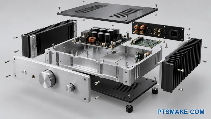

An aluminum housing can look complete while seams, finishes, and cable entries weaken its shielding. Late discoveries can force new parts and repeat tests.
Quick answer: EMI enclosure design starts with the product’s EMC requirements and a map of every shield interface. Machined aluminum housings need controlled conductive surfaces, seams, gaskets, openings, and cable connections. The product team then validates a representative assembly under agreed operating and test conditions.
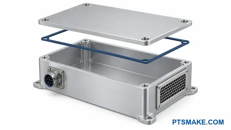
This guide turns those requirements into drawing notes, supplier responsibilities, and a test-ready build record. The tables show which decisions belong in your RFQ and which need approval from your EMC team.
You can share your enclosure drawings and interface questions with PTSMAKE.
Set the EMC Scope and Map Enclosure Interfaces
Define the EMI Enclosure Design Brief
The product owner should name the engineer or laboratory responsible for electromagnetic compatibility, or EMC. That owner defines the required performance and the evidence needed to approve the product. A conductive housing is one part of the system.
Electromagnetic interference, or EMI, can reach a circuit through fields or connected conductors. The design brief should cover the relevant paths.
The brief should identify the intended market, installation environment, operating modes, and connected equipment. It should also identify the relevant emissions and immunity requirements. For example, the public scope of EMC immunity requirements in IEC 61000-6-21 addresses industrial environments when no relevant dedicated product standard applies. The EMC owner must select the applicable requirements for the actual product.
The electrical team should identify suspected sources and sensitive circuits. The team may need information about switching devices, clocks, motors, transformers, and nearby equipment. Frequency range and operating state matter because the housing must address a defined problem.
Shielding effectiveness2 depends on the field, frequency, material, and assembly. Low-frequency magnetic-field problems need separate attention. An aluminum enclosure should not be treated as a universal answer to a nearby transformer or other magnetic source.
Map the Shield Boundary and Every Interface
I start with a marked assembly view because it makes the scope visible to every supplier. The view should show what needs protection and where signals, power, air, light, and mechanical connections cross the enclosure boundary.
The electrical team may choose a full housing, a local shield, or several coordinated measures. The drawing should record that choice. It should also identify antennas and intentional radio paths that the enclosure must preserve.
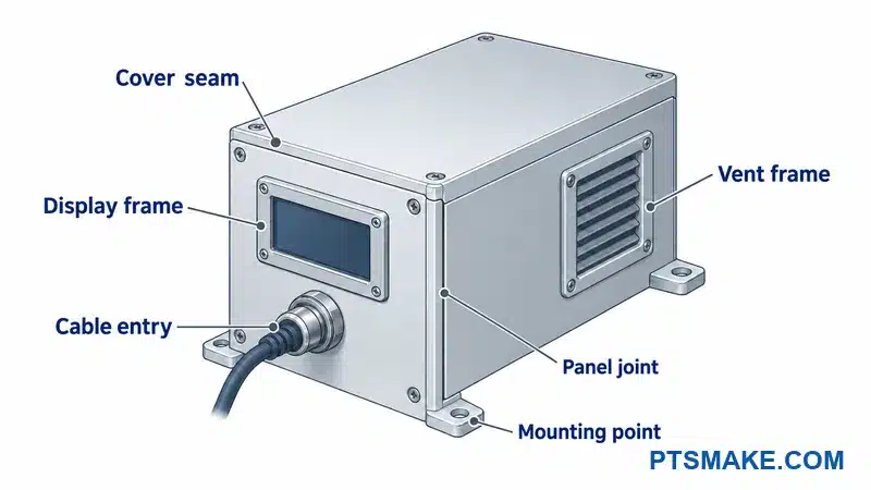
The following register is a planning template. The project team supplies the actual references and owners.
| Gränssnitt | Information to mark | Decision owner | Evidence to retain |
|---|---|---|---|
| Cover or removable panel | Joint path, contact zones, opening direction | Mechanical and EMC engineers | Approved joint detail |
| Connector and cable entry | Part number, shield and filter arrangement | Electrical engineer | Interface drawing and cable schedule |
| Display or vent | Opening function and complete insert assembly | Product and EMC engineers | Approved opening assembly |
| Mounting or contact point | Mechanical purpose and electrical role | Mechanical and electrical engineers | Defined contact or isolation requirement |
The map should include internal hardware that changes the installed condition. Mounting brackets, cable clamps, and board supports can affect routing and access. The aluminum amplifier chassis DFM guide provides an application-specific example of coordinating enclosure interfaces.
Separate RF Bonding from Protective Earth
The drawing should distinguish protective-earth connections, signal references, and RF bonding3. These connections have different purposes. NASA’s bonding handbook explains why a DC resistance measurement alone cannot establish RF bond effectiveness.
The product’s electrical owner should approve each connection and its verification method. A machining drawing should not leave the supplier to infer the grounding scheme from a bare contact patch or a screw symbol.
Define Conductive Materials and Finish Zones
Specify the Complete Material and Finish Stack
The buyer should specify the substrate and every intended surface treatment together. A material name alone does not describe the final contact condition. Anodizing and paint can insulate a contact surface, while other treatments may be selected to support an approved conductive interface.
Proposed conversion coatings or plating also need review against the required final contact condition and corrosion protection. The finishing and electrical owners should approve the complete treatment stack.
The finish specification should identify where each treatment applies. The drawing should also state which requirements apply after finishing. A machined contact land that meets its dimensions before coating may still need a separate check after the full process.
I would ask the design team to approve a finish map before the supplier quotes the part. That map connects the electrical requirement to a visible area on the drawing. It also gives the finisher a basis for quoting masking, handling, and inspection.
The team should record the material grade, product form, and relevant finish specification revisions. The supplier should identify any proposed substitutions in the quotation. A different substrate or finish should receive the relevant technical review before it becomes the production choice.
Den clear anodized finish considerations provide background on that surface treatment. The enclosure’s conductive zones still need their own approved requirements. The team should not assume that a decorative finish specification defines electrical contact performance.
Mark Conductive, Cosmetic, and Protected Surfaces
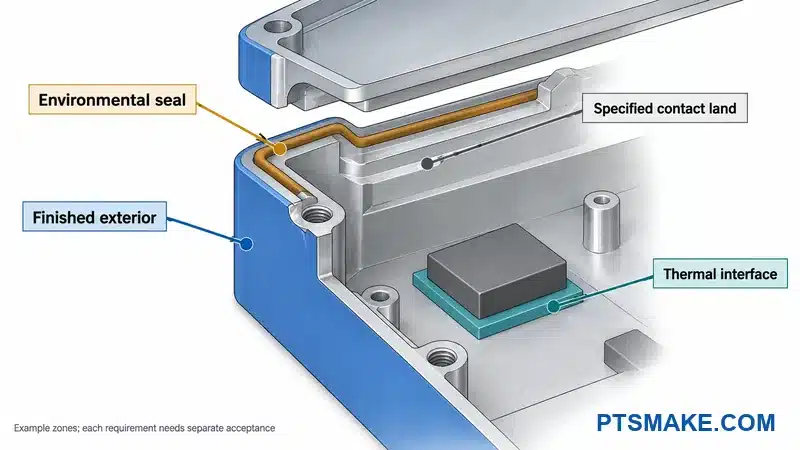
A useful finish map separates exterior appearance, conductive contact, thermal contact, and environmental protection. Some areas serve more than one role. The drawing should identify those shared areas so the owners can resolve any conflict before release.
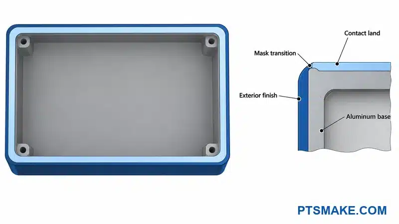
For example, a hypothetical instrument housing has a finished outer cover and a defined contact land around its inside edge. The buyer may allow a visible transition on the inside while rejecting that transition on the front face. The electrical and appearance owners should approve the same boundary.
The map should show the full extent of the contact area. It should cover corners, fastener seats, connector flanges, and any interrupted sections. A general note such as “mask contact surfaces” leaves too much room for different interpretations.
The contact land should have an approved surface condition and protection method. Masking alone does not define how that area will resist corrosion or survive handling. The finishing and corrosion owners should decide which treatment and protection are suitable for the intended environment.
The buyer should state who prepares the contact surface and when that work occurs. The sequence may involve the machinist, finisher, assembler, or a specialist supplier. The quotation should make that responsibility visible instead of assuming another party will complete it.
The illustration uses colors and exaggerated layer thickness to identify the zones. Its layer sizes are not manufacturing requirements.
Control Mask Boundaries and Contact Condition
The drawing should define how the supplier locates a masking boundary. The requirement can refer to a controlled edge, datum, or detail view. The chosen reference should remain available through the finishing process.
The project should also define how it will inspect the boundary. The inspection record may include the zone identifier, finish revision, inspection method, and any approved deviation. A photograph can record location or visible condition, but it should not replace a required electrical or dimensional check.
The assembly instructions should state which contact areas need protection during cleaning, storage, and assembly. The instructions should also identify permitted preparation methods. Uncontrolled scraping or sanding can change the approved interface and create inconsistent parts.
The buyer should address rework before production. A local finish repair, repeated coating process, or changed masking method may need review from more than one owner. The supplier needs a clear route for approval when the drawing does not cover the proposed repair.
The release package should link each critical zone to its acceptance requirement and owner. This makes the requirement inspectable without turning every visible surface into a tight-tolerance electrical interface. The team can then focus control on the areas that support the approved design.
Control Seams, Covers, and Gasket Interfaces
Choose a Joint for Assembly and Service
A cover joint must satisfy its mechanical and electrical roles in the assembled product. The design team should consider contact continuity, assembly access, cleaning, appearance, and expected service cycles together. A joint that is easy to machine may still be difficult to assemble consistently.
The interface drawing should show the mating parts and the intended contact path. It should identify breaks caused by openings, corners, fastening features, or separate panels. The EMC owner should review the complete path rather than approve an isolated straight section.
The team should decide whether the joint is permanent or serviceable. A serviceable cover needs a defined opening method and a way to restore the approved interface. The requirement should state whether a gasket can be reused or needs replacement after opening.
Fastener access belongs in this review. The assembly team should be able to install and tighten the required hardware in the intended sequence. The design should also account for tools, nearby cables, and any parts that hide the joint during assembly.
The drawing should identify the fastener type and relevant assembly instruction. The responsible engineer should set any torque or sequence requirement. The supplier should not select a universal screw pitch or torque value from a general enclosure article.
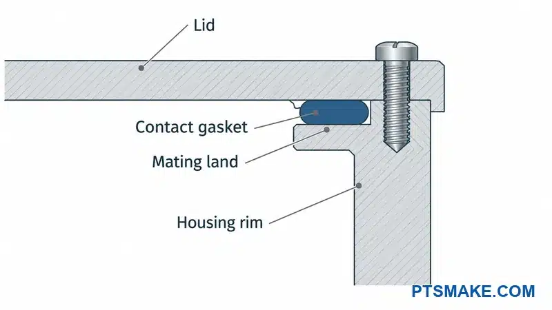
Define Gasket Compression with Its Supplier
The gasket specialist needs more than the outline of a groove. The selection brief should include the mating materials and finishes, environment, space, closure method, and expected opening cycles. It should also identify production quantities and any separate environmental sealing requirement.
Galvanisk kompatibilitet4 depends on the material pairing and exposure conditions. Parker’s fingerstock guide also addresses repeated opening and closing. Those considerations support a project-specific selection; they do not make one gasket technology suitable for every housing.
The supplier should provide the approved part number and application requirements. The project should record the permitted mating condition, compression or deflection range, joining details, and replacement rules. The requirements must come from the selected product and application review.
The machinist’s scope should identify the geometry needed to support those requirements. The gasket supplier should approve the interface assumptions. The assembler should confirm that the specified installation method is practical with the actual housing and hardware.
I treat a gasket datasheet as selection evidence. A catalog shielding value does not establish the performance of the complete enclosure or the finished electronic product. The project still needs the agreed assembly and system-level validation.
Review Flatness, Stops, and the Assembly Stack
The mechanical engineer should evaluate the closed assembly across the allowed variation in its parts. Relevant inputs may include the lid, contact land, gasket, finish, fasteners, and locating features. Their combined condition determines the installed geometry.
An example design may use a controlled stop to limit closure. Another design may use a different method approved by its gasket specialist. The drawing should explain the intended method without assuming that every gasket needs the same groove or stop.
The review should consider local conditions as well as overall fit. Corners, spans between fasteners, and changes in section may deserve separate attention. The team should identify which dimensions or surface conditions need measurement to control those areas.
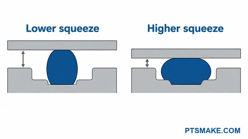
Preserve Contact Through Opening Cycles
The service procedure should identify parts that wear, move, or need replacement. It should explain how the technician checks the mating surfaces before closing the housing. The procedure should also state how any damage or contamination is handled.
The buyer should define acceptable witness marks on serviceable surfaces. A cosmetic limit that rejects every contact mark may conflict with the chosen joint. The appearance and electrical owners should resolve that conflict using the actual assembly concept.
Prototype reviews should include the intended opening and reassembly sequence. The project team can then assess whether the instructions preserve the required configuration. A successful first closure does not answer every service-life question.
You can include the joint drawings and selected gasket requirements with your enclosure inquiry.
Review Connectors, Displays, and Vents as Shield Interfaces
Specify Cable and Connector Boundary Conditions
The enclosure drawing should identify every cable entry, connector opening, and unused port. Each item needs a defined installed condition. An empty machined cutout and a fully assembled connector interface are different configurations for the EMC review.
The cable schedule should identify the cable type, connector pair, shield arrangement, and any required filtering. It should also identify the electrical owner of those choices. The machining supplier needs the approved geometry and contact requirements, not responsibility for an unspecified electrical interface.
Cable shield termination5 affects the shielding arrangement. TI’s enclosure guidance treats the enclosure wall, openings, and cable entry or exit as related concerns. It also advises considering cables and connectors together.
The interface detail should show the connector shell, flange, mounting hardware, and contact surface where these features are relevant. The drawing should identify any required conductive treatment or masking at the interface. The electrical team should approve the complete path.
The project should record what happens when a port is unused. A cap, blanking panel, or other closure may be part of the intended configuration. Its material, fit, contact condition, and retention should receive the relevant review.
Keep Shield Termination Distinct from Signal Return
The electrical design should state the role of the cable shield and the signal conductors. The supplier should not infer that a connector shell, signal return, and protective-earth point are interchangeable. The wiring and assembly instructions must preserve the approved arrangement.
The illustration below shows a conceptual shielded cable interface. The electrical owner selects the actual termination scheme for the product. The drawing does not establish a universal rule for connecting every shield at every frequency.
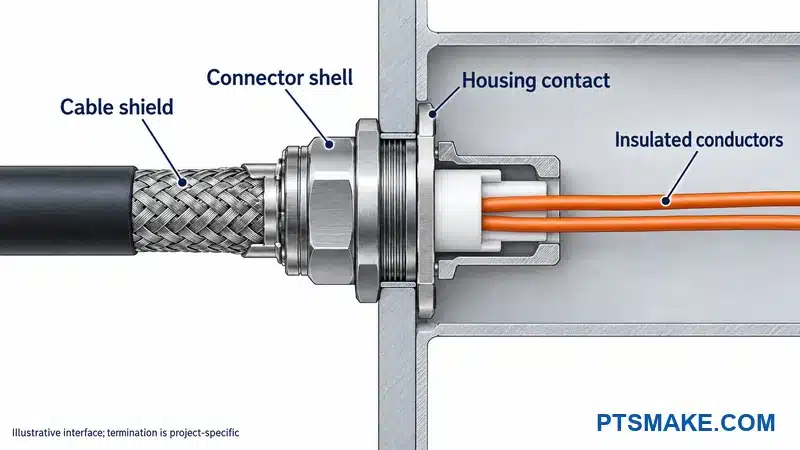
Resolve Airflow and Optical Openings
The product team should list what each opening must do. A vent needs an airflow requirement and a defined assembly. A display window needs an optical requirement and an approved mounting arrangement. Those functions should remain visible during the EMC review.
The opening schedule should identify each opening’s size, location, insert or assembly, owner, and mounting details. The schedule should also record any supplier assumptions. A quotation based only on the outer cutout may omit a required frame, contact detail, seal, or purchased component.
I would review a vent as a complete assembly. The team should check how its frame connects to the housing and how the chosen finish affects that interface. The EMC owner and thermal owner should assess the same installed design.
The design review should consider the space around the opening. Internal hardware, cable routing, and nearby walls may restrict the intended airflow or assembly access. The thermal requirement should describe the product’s operating condition rather than rely only on the vent’s nominal open area.
A display interface may involve several layers and suppliers. The buyer should identify which party provides the window, any shielding measure, the frame, and the electrical contact arrangement. The team should also agree on inspection and replacement responsibilities.
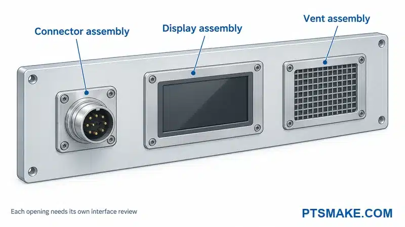
Assess the Complete Opening Assembly
The engineering team should approve the final opening arrangement with its actual components. A general hole-size rule cannot account for every frequency, geometry, material, and interface.
The RFQ should show the required assembly condition for delivery. The supplier may quote only a machined housing, or the agreed scope may include selected purchased items. The quotation should identify who completes any remaining assembly before validation.
The prototype record should capture changes made around openings during testing. A temporary cover, added clamp, substituted cable, or revised connector contact may become a necessary production requirement. The team should resolve those changes in controlled documents before release.
Resolve Thermal, Corrosion, and Appearance Tradeoffs
Compare Requirements at Shared Surfaces
An enclosure surface may support several functions at once. A cover edge can affect appearance, environmental sealing, electrical contact, and service access. The responsible owners should review those functions together before one requirement becomes fixed.
A sealing requirement does not automatically define an EMI gasket requirement. The project may need separate seals or a product selected for both functions. The relevant specialists should approve the intended combination and its installed condition.
The team should also define the expected environment. Moisture, cleaning chemicals, handling, and repeated opening can change the selection question. The RFQ should identify those conditions so suppliers can state assumptions instead of silently choosing different solutions.
The following table is a decision template. The buyer supplies the actual requirement and accepted tradeoff for each relevant interface.
| Shared requirement | Possible conflict | Decision owners | Evidence and quotation effect |
|---|---|---|---|
| Conductive cover contact | Exterior finish and visible mask edge | EMC, finish, and appearance owners | Approved zone drawing; masking and inspection scope |
| Ventilation | Environmental protection and shield boundary | Thermal, mechanical, and EMC owners | Approved vent assembly; purchased parts and test scope |
| Gasket contact | Corrosion protection and service cycles | Gasket, finish, and mechanical owners | Compatible interface selection; replacement and supply assumptions |
| Termisk kontakt | Assembly space and electrical isolation | Thermal and electrical owners | Approved interface stack; material and assembly requirements |
| Removable panel | Cosmetic marks and reliable reassembly | Service, appearance, and EMC owners | Service procedure; permitted marks and replacement parts |
Record Accepted Tradeoffs and Their Owners
The project should keep one decision record for each unresolved interface. The record should name the owner, required evidence, due date, and affected drawing or specification. The supplier needs to know which details are fixed and which remain assumptions.
A change in one requirement should trigger review of the affected shared surfaces. For example, a hypothetical change from indoor use to a moisture-prone location may alter the approved contact protection. The team should assess the finish, gasket, and inspection implications together.
Appearance limits should describe what the buyer can accept around those interfaces. The cosmetic acceptance criteria for aluminum enclosures can support that separate discussion. An appearance approval does not replace approval of the electrical contact condition.
The quotation should identify any cost or schedule effect from unresolved choices. The buyer can then compare offers using the same assumptions. A lower quoted price is difficult to assess when one supplier includes the interface work and another leaves it undefined.
Assign Owners and Prepare a Complete RFQ
Define Responsibility Across the Supply Chain
The buyer should assign responsibility for machining, finishing, masking, gasket supply, assembly, inspection, and EMC testing. One supplier may coordinate several steps, but the quotation should still identify their scope and approval route.
The machining supplier can quote the agreed geometry and documented inspection requirements. The product’s electrical and EMC owners should approve the electrical architecture and validation plan. Any specialist work should have a named provider and a clear technical handoff.
The table below combines the responsibility split with the files needed for an RFQ. Every owner and document reference is a project entry, not a claim about services supplied by PTSMAKE.
| Paketpost | Buyer-controlled input | Responsibility to confirm | Evidence or deliverable |
|---|---|---|---|
| Housing geometry | Current 3D model, 2D drawing, quantities and phases | Machining scope and drawing approver | Agreed dimensions and inspection record |
| Finish and contact zones | Material, finish specification, mask map | Finisher, contact preparation owner, approver | Finish records and zone inspection |
| Gaskets and inserts | Approved part numbers and application details | Supply, installation and specialist approval | Component traceability and assembly record |
| Connector and cable interfaces | Cutouts, wiring and interface schedule | Electrical design and supplied-component scope | Approved installed configuration |
| Mechanical assembly | Hardware list and controlled instructions | Assembly, rework and service responsibility | Assembly checks and recorded deviations |
| EMC evaluation | Requirements, operating modes and test plan | Product EMC owner and chosen test provider | Agreed test evidence and disposition |
| Packing and change control | Protected zones and notification rules | Packing, traceability and change-review owners | Identified shipment and revision records |
Issue One Controlled RFQ Package
The purchasing team should issue one document list with revision identifiers. The list should link the assembly model, part drawings, interface map, finish requirements, component schedule, and required records. Every bidder should receive the same information.
The RFQ should identify prototype and production quantities separately. It should also describe who supplies purchased components and when those parts will be available. A missing connector or gasket can affect an assembly review even when the machined housing is ready.
The package should connect the interface requirements to the CNC milling requirements and inspection scope. The supplier can then state which requirements it accepts and which need further review.
Make Quote Assumptions and Exclusions Visible
I ask for a written assumptions list because it makes competing offers easier to compare. The list should identify unresolved finish zones, missing component data, excluded assembly work, and any testing supplied by others.
The buyer should name who approves changes to those assumptions. Purchasing can coordinate the response, but technical owners should approve changes within their areas. A commercial acceptance should not silently replace a missing engineering decision.
The order should identify the documents that control if notes conflict. It should also state how deviations are approved and recorded. This gives the supplier a usable route for questions without treating every clarification as permission to change the design.
You can send PTSMAKE the housing files, interface map, quantities, and open RFQ items for review.
Validate Production-Representative Prototypes
Separate Fit Checks from EMC Validation
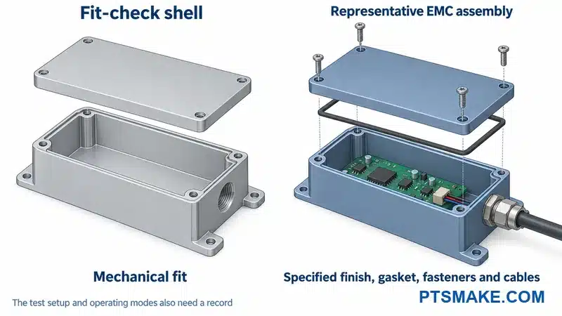
A fit prototype can answer questions about component clearance, assembly access, and cover alignment. An EMC validation build needs the configuration defined by the product’s EMC owner. The project should label each build by its purpose so its results are used correctly.
EMC validation testing6 can occur at different development stages. TÜV Rheinland describes development, final-prototype, and production testing in its electromobility guidance. That example does not prescribe one test schedule for every electronic product.
The project team should agree which features must represent production for the planned evaluation. Materials, finishes, gasket details, fasteners, cables, internal hardware, and assembly condition may all need control. The test provider should review any known differences before the team relies on the result.
Continuity checks assess specified electrical connections using an agreed method. Pre-compliance testing helps the team find and resolve problems during development. The required final EMC assessment evaluates the defined equipment configuration against the applicable requirements. The EMC owner should identify the evidence needed at each stage.
Freeze the Test Configuration and Resolve Deviations
The team should create a build record before testing. The following table is a project template rather than a standard’s mandatory checklist.
| Configuration item | Record to retain | Question before testing |
|---|---|---|
| Housing and cover | Drawing and material revisions | Do the parts match the intended interface design? |
| Finish and contact preparation | Finish revision and zone inspection | Are the required contact conditions present? |
| Gaskets and hardware | Part numbers and assembly record | Does the closed assembly follow the approved instructions? |
| Cables and connectors | Cable schedule and routing record | Is the connected configuration representative? |
| Electronics and operation | Hardware, firmware and operating modes | Does the test exercise the agreed conditions? |
| Prototype deviations | Written list and owner approval | Does each difference limit the use of the result? |
Record Cables, Fasteners, Finishes, and Operating Modes
The record should describe the actual tested unit, including approved deviations. Photographs can support the record where they clearly show routing or assembly state. The team should also retain controlled document references so the configuration can be reproduced.
Any change made during debugging should enter the record. A temporary contact strip, different cable, or altered cover assembly may explain a change in performance. The team should decide whether that change becomes part of the released design.
The EMC owner should define the scope of further evaluation after a change. The result may support some decisions while leaving others open. The team should not assume that every result transfers unchanged to a different finish, joint, or cable arrangement.
The supplier should receive the released requirements that follow from validation. A test report alone may not identify every manufacturing action. The updated drawings and assembly instructions should make those actions clear before production begins.
Control Supplier Evidence and Production Changes
Review Process Evidence and Traceability
The buyer should assess how a supplier will control the agreed interfaces. Relevant evidence may include enclosure examples, inspection methods, finishing coordination, component traceability, and nonconformance procedures. The evaluation should focus on the actual order requirements.
The supplier should explain how drawing and finish revisions reach any subcontractors. The buyer should also confirm how substituted components or changed processes are proposed for approval. A controlled supplier chain needs a clear link between the released requirement and the delivered part.
Inspection records should identify the part, lot, revision, method, and result where the order requires them. The records should also identify approved exceptions. The project should define who can accept a deviation and whether the approval applies to one lot or a lasting design change.
Packaging should protect the features that matter at assembly. Contact lands, delicate gasket features, and finished surfaces may need different protection. The packing instructions should identify those areas without leaving residue or handling marks that conflict with the approved requirements.
Define Changes That Need Engineering Review
The order should require notification of changes that could affect the approved configuration. The table below identifies review topics; it does not require a complete retest for every change. The EMC owner and other responsible engineers decide the necessary evidence.
| Proposed change | Review focus | Owners to involve |
|---|---|---|
| Material or finish | Contact condition, corrosion protection and controlled dimensions | Mechanical, finish and EMC owners |
| Gasket, insert or supplier | Application limits, compatibility and installed condition | Gasket specialist, quality and EMC owners |
| Cover or fastener arrangement | Contact path, compression and service sequence | Mechanical, assembly and EMC owners |
| Connector, cable or vent | Boundary treatment, routing and complete opening assembly | Electrical, thermal and EMC owners |
| Repair or assembly method | Difference from the approved build and its evidence | Relevant technical owner and quality |
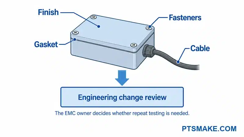
The change record should identify affected lots and the point at which the change takes effect. The team should retain the decision, supporting evidence, and revised documents together. Production and inspection staff then have a clear basis for applying the approved change.
The release owner should close open interface decisions before the affected production step begins. Any permitted exception needs a defined scope and approval. The supplier should not have to infer the final requirement from an informal test adjustment or an unmarked replacement component.
Discuss Your EMI Enclosure RFQ
You can share your housing drawings, finish-zone map, selected components, and open interface questions with PTSMAKE. Your package can identify the machining and inspection requirements that need agreement before quotation and prototype production.

IEC 61000-6-2 defines a particular generic industrial immunity scope. The product’s EMC owner must identify applicable standards and editions; this reference is not a universal enclosure requirement. ↩
Shielding effectiveness describes attenuation under stated conditions. Parker explains why field type, material and interface continuity matter; theoretical or material values do not establish complete-product performance. ↩
RF bonding concerns the electrical behavior of connected structures at radio frequencies. NASA’s handbook distinguishes this from fault protection and cautions against using DC resistance alone to judge RF performance. ↩
Galvanic compatibility concerns the behavior of contacting materials in their environment. The fingerstock guide supports reviewing finishes, exposure and service conditions for the selected gasket system. ↩
Cable shield termination describes how the cable shield connects at an interface. TI’s guidance explains why enclosure openings and the cable/connector arrangement need coordinated review. ↩
EMC validation testing evaluates an agreed equipment configuration against defined requirements. The cited laboratory page describes testing stages for electromobility; the actual product team determines its own test program. ↩