Looking at your heat pipe heat sink manufacturing guide, I can see the challenges you face daily. Finding reliable manufacturers who understand both the complex thermal engineering and precision manufacturing requirements often leads to project delays and performance compromises.
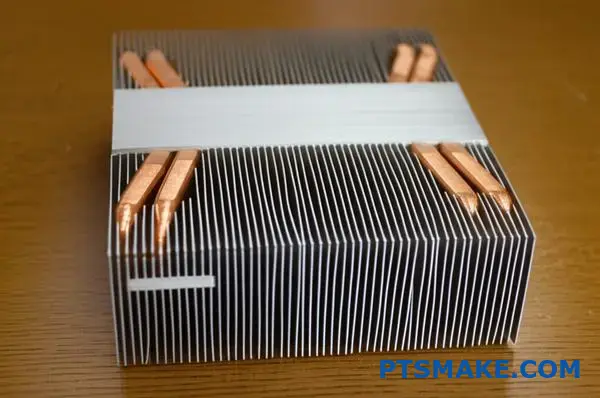
Heat pipe heat sinks are sophisticated thermal management devices that use two-phase heat transfer to efficiently move heat from high-power sources to larger surface areas for dissipation, combining heat pipes with finned structures for optimal cooling performance.
Through my experience at PTSMAKE, I’ve worked with engineering teams who struggled with thermal design decisions and manufacturing partnerships. This comprehensive guide breaks down the technical fundamentals and practical considerations you need to make informed decisions for your next thermal management project.
What is the core working principle of a heat pipe?
The Physics of Passive Cooling
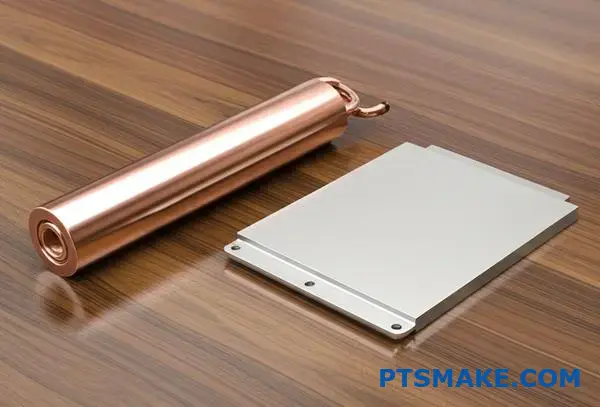
At PTSMAKE, we often observe engineers amazed by how a simple hollow tube outperforms solid copper. A heat pipe heat sink does not just conduct heat; it transports it through phase changes. This makes it incredibly efficient for thermal management.
The secret lies in a continuous, passive cycle. It moves energy from a hot source to a cool interface without moving parts. This reliability is why we recommend them for precision electronics.
| Feature | Solid Copper Rod | Heat Pipe |
|---|---|---|
| Mechanism | Simple Conduction | Phase Change (Two-Phase) |
| Conductivity | ~400 W/m·K | 10,000+ W/m·K (Effective) |
| Response | Slower Thermal Lag | Near Instantaneous |
Breaking Down the Thermodynamic Cycle
The efficiency of a heat pipe comes from utilizing the enthalpy of vaporization1. When the device touches a heat source, the working fluid inside boils. It absorbs significant thermal energy during this state change.
Vapor Transport and Condensation
The resulting vapor creates a localized high-pressure zone. This forces the gas to flow rapidly toward the cooler end of the pipe. It is simple fluid dynamics in action.
At the condenser section, the vapor releases its latent heat. It transforms back into a liquid state. This rapid energy dump allows for the high effective thermal conductivity we see in lab results.
Liquid Return Mechanism
The cycle completes when the liquid returns to the evaporator. This is driven by the wick structure lining the pipe walls. It acts like a sponge.
| Stage | Physical Action | Thermodynamic Result |
|---|---|---|
| 1. Evaporation | Fluid boils at hot interface | Absorbs Latent Heat |
| 2. Transport | Vapor flows to cold end | Mass transfer driven by pressure |
| 3. Condensation | Vapor turns to liquid | Releases Latent Heat |
| 4. Return | Liquid flows back via wick | Capillary forces overcome drag |
In our experience with custom projects, the quality of the wick determines the pipe’s orientation limits. We ensure the capillary forces are strong enough for the specific application.
The core principle relies on a self-sustaining two-phase cycle. By continuously converting liquid to vapor and back, the heat pipe transfers massive amounts of thermal energy via latent heat. This process provides superior cooling performance compared to traditional solid conduction methods.
What are the essential components of a heat pipe?
When we manufacture a heat pipe heat sink at PTSMAKE, we focus on three critical elements. These parts work together to manage thermal energy efficiently. It isn’t just a metal tube; it is a precise system.
The main components are the container, the working fluid, and the wick structure. Each has a distinct role in the thermal cycle. Without precision in any one part, performance fails.
| Component | Primary Function |
|---|---|
| Container | Maintains vacuum and mechanical structure |
| Working Fluid | Transports heat via phase change |
| Wick Structure | Returns fluid via capillary action |
The Container: More Than Just a Shell
The container, usually copper or aluminum, must withstand internal pressure. It isolates the internal environment from the outside. In our testing at PTSMAKE, even microscopic leaks destroy the vacuum, stopping the process.
The Wick and Fluid Interaction
The magic happens inside. The working fluid absorbs heat at the evaporator end. This energy causes the fluid to vaporize. This phase change utilizes Latent Heat2 to transport massive amounts of energy quickly.
The vapor travels to the cooler end, known as the condenser. Here, it releases heat and turns back into liquid.
The Critical Return Path
This is where the wick structure becomes vital. It acts like a sponge. Using capillary action, it pulls the condensed liquid back to the heat source against gravity.
Common Wick Types
Different applications require different internal structures to balance flow resistance and pumping power.
| Wick Type | Capillary Force | Permeability | Typical Application |
|---|---|---|---|
| Sintered Powder | High | Low | High-power electronics |
| Grooved | Low | High | Horizontal transfer |
| Wire Mesh | Medium | Medium | General purpose |
Choosing the right combination ensures the heat pipe heat sink operates at peak efficiency. We often advise clients that a mismatch here leads to component dry-out.
To summarize, a heat pipe relies on the synergy between a sealed container, a specific working fluid, and a precise wick. The fluid moves heat through phase changes, the wick returns liquid, and the vacuum seal ensures the cycle repeats continuously for effective cooling.
What are the primary operational limits of a heat pipe?
Understanding the Boundaries
A heat pipe heat sink is a highly efficient thermal solution, but it is not invincible.
In our engineering experience at PTSMAKE, we know that pushing a device beyond its physical thresholds leads to immediate failure.
You must identify these operational ceilings early in the design phase to avoid costly revisions.
Key Limit Categories
| Limit Type | Primary Constraint |
|---|---|
| Capillary Limit | Wicking structure capacity |
| Boiling Limit | Vapor bubble formation |
| Sonic Limit | Vapor velocity speed |
| Viscous Limit | Vapor pressure drop |
The Physics Behind the Failures
Let’s break down exactly why these limits occur during operation to help you design better systems.
The Capillary and Boiling Thresholds
The capillary limit is the most common issue we encounter in high-power applications.
It happens when the capillary pressure is too weak to pump liquid back to the evaporator against friction.
The result is a "dry-out" at the heat source.
The boiling limit occurs when the radial heat flux is too high.
| Failure Mode | Physical Cause | Practical Result |
|---|---|---|
| Capillary Failure | Liquid returns too slowly | Evaporator dries out completely |
| Boiling Failure | Trapped vapor bubbles | Wall temperature spikes rapidly |
Sonic and Viscous Constraints
These limits usually appear during startup or in cryogenic conditions.
The sonic limit is reached when vapor velocity hits the speed of sound at the evaporator exit.
This creates a choked flow condition, capping the heat transfer rate regardless of input power.
Another critical factor to consider is the Entrainment limit3.
This phenomenon happens when high-speed vapor shears liquid droplets off the wick surface, preventing them from returning.
In our testing results at PTSMAKE, we confirm that viscous limits dominate at very low temperatures.
Here, the vapor pressure is simply insufficient to overcome the pressure drop, stalling the heat pipe heat sink entirely.
Understanding these physical limits is vital for designing a reliable heat pipe heat sink. By analyzing capillary, boiling, and sonic thresholds, we ensure your thermal solution performs safely under real-world loads without risking catastrophic failure.
How does a heat pipe heat sink work as a system?
To truly appreciate the efficiency of a heat pipe heat sink, we must follow the thermal energy’s journey. It functions like a high-speed highway system for heat, moving it away from critical components.
At PTSMAKE, we visualize this flow clearly when optimizing thermal designs for our clients. The system relies on a continuous, passive cycle.
| Stage | Primary Function | Location |
|---|---|---|
| Evaporation | Absorbs heat | Heat Source |
| Transport | Moves vapor | Adiabatic Section |
| Condensation | Releases heat | Fin Stack |
Let’s break down the specific physics occurring at each stop along this thermal path.
The Evaporator Interface
The process begins at the heat source, such as a CPU or power transistor. The heat pipe’s copper wall conducts this thermal energy directly into the internal wick structure.
Inside, the working fluid absorbs this energy and boils instantly. In our testing results comparison, efficient evaporation is the bottleneck for overall performance.
The Adiabatic Transport
Once vaporized, the gas travels rapidly toward the cooler end of the pipe. This middle area is called the adiabatic section.
Ideally, no heat transfer occurs here. It acts simply as a tunnel. In past projects, we found that excessive bending in this section can hinder vapor velocity.
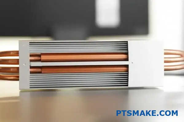
Condenser and Fin Interaction
Upon reaching the cool end, the vapor condenses back into a liquid state. It releases the energy it stored during the vaporization phase.
This heat transfers into the attached aluminum fins of the heat pipe heat sink. The fins increase the surface area, allowing ambient air to carry the heat away.
| Component | State of Fluid | Mechanical Role |
|---|---|---|
| Evaporator | Liquid to Vapor | Energy Input |
| Adiabatic Zone | Vapor Flow | Mass Transport |
| Condenser | Vapor to Liquid | Energy Output |
The liquid then returns to the evaporator through the wick structure. This continuous loop is powered by the massive energy exchange known as Latent Heat of Vaporization4.
To summarize, the system creates a closed-loop thermal cycle. Heat enters the evaporator, travels quickly as vapor, and exits through the condenser into the cooling fins. This efficient movement allows a heat pipe heat sink to manage high thermal loads reliably without any moving mechanical parts.
Why are heat pipes sealed under a vacuum?
The vacuum seal is the defining feature of a functional heat pipe. Without this depressurized environment, the phase change cycle simply cannot occur efficiently. It is not just about keeping the fluid inside.
Creating a vacuum alters the thermodynamic properties within the copper envelope. This adjustment allows the system to react instantly to thermal loads.
| State | Internal Pressure | Boiling Point Effect |
|---|---|---|
| Atmospheric | Standard (1 atm) | High (e.g., Water @ 100°C) |
| Vacuum | Extremely Low | Low (e.g., Water @ 30°C) |
We need the fluid to vaporize at the exact moment heat touches the evaporator. By removing non-condensable gases, we ensure the internal pressure is determined solely by the fluid’s vapor.
This relationship allows us to tune the saturation pressure5 to specific needs. For example, in electronics cooling, we want the fluid to boil around 30°C to 40°C.
If we left air inside, the water would sit stagnant until it hit 100°C. That would be catastrophic for a CPU or sensitive hardware.
| Vacuum Level | Boiling Point (Water) | Application Example |
|---|---|---|
| Partial | 60°C – 80°C | High-temp Industrial machinery |
| High | 20°C – 40°C | Precision Consumer electronics |
| None | 100°C | Ineffective for cooling |
In our testing at PTSMAKE, we found that precise vacuum control dictates the startup temperature. A perfect seal ensures the heat pipe heat sink operates across a wide thermal range.
This mechanism turns a passive component into a super-conductor of thermal energy. It effectively bypasses the natural thermal resistance of the metal shell.
Sealing the heat pipe under a vacuum significantly lowers the boiling point of the working fluid. This enables rapid phase change at safe operating temperatures, ensuring the heat pipe heat sink manages thermal loads efficiently across diverse applications.
How do vapor chambers differ from cylindrical heat pipes?
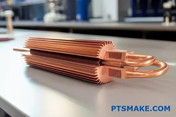
At PTSMAKE, we often explain that the geometry dictates performance. A traditional cylindrical heat pipe is a sealed tube designed for linear transport. It moves heat efficiently from point A to point B.
Conversely, a vapor chamber acts like a planar heat pipe. It consists of two stamped metal plates sealed together. This structure allows heat to spread in two dimensions simultaneously, offering superior surface coverage.
| Feature | Cylindrical Heat Pipe | Vapor Chamber |
|---|---|---|
| Geometry | Tubular / Round | Flat / Planar |
| Heat Flow | Linear (1D) | Multi-directional (2D) |
| Structure | Sealed copper tube | Vacuum-sealed metal plates |
When designing a heat pipe heat sink, understanding this structural distinction is the first step. The choice depends on whether you need to move heat far away or spread it out quickly.
The core advantage of a vapor chamber lies in its ability to manage high flux densities. In our testing at PTSMAKE, we observe that cylindrical pipes work best when heat needs to travel a long distance to remote fins.
However, when the heat source is small but powerful, a flat chamber is superior. It eliminates the bottleneck of transferring heat from a square chip to a round tube.
This reduction in thermal resistance is achieved because the chamber creates direct contact. The vapor fills the entire void, ensuring even temperature distribution across the surface of the base.
Mechanically, vapor chambers use internal pillars or sintered powder. This supports the structure against atmospheric pressure while allowing the working fluid to utilize Latent Heat of Vaporization6 effectively.
| Criterion | Cylindrical Heat Pipe | Vapor Chamber |
|---|---|---|
| Transport Distance | Effective for >50mm | Best for localized spreading |
| Source Contact | Tangential (Line contact) | Full Surface (Face contact) |
| Vertical Space | Requires bending radius | Extremely low profile |
From a manufacturing perspective, integrating a vapor chamber can reduce the total weight of the heatsink assembly. We often recommend this for aerospace clients where every gram counts.
Ultimately, while a standard heat pipe moves heat, a vapor chamber acts as a thermal equalizer. It transforms a concentrated hot spot into a uniform thermal field for the heatsink to manage.
Cylindrical pipes excel at linear transport over distances, whereas vapor chambers are planar devices ideal for spreading concentrated heat. The choice depends on whether your design prioritizes long-range transfer or immediate hotspot management.
How are heat pipe heat sinks categorized by material?
Selecting the right materials for a heat pipe heat sink is crucial for performance. The container shell and the working fluid must match perfectly.
In PTSMAKE’s past projects, we categorize these components based on thermal conductivity and chemical stability.
Below are the common container materials we utilize in manufacturing.
| Container Material | Typical Application |
|---|---|
| Copper | Electronics cooling (CPU/GPU) |
| Aluminum | Aerospace and weight-sensitive parts |
| Stainless Steel | Medical or cryogenic devices |
The working fluid is equally important for transporting thermal energy. We select these based on the operating temperature range.
| Working Fluid | Useful Range |
|---|---|
| Water | 30°C to 200°C |
| Ammonia | -60°C to 100°C |
| Methanol | -86°C to 100°C |
The Critical Role of Compatibility
You cannot simply mix any fluid with any metal container. If the combination is chemically unstable, reactions occur inside the sealed pipe.
Based on our internal testing, incompatible pairs often generate Non-Condensable Gas7 over time. This gas accumulates at the top of the pipe.
It effectively blocks the condensation process. Consequently, the heat pipe heat sink stops transferring heat efficiently.
To ensure longevity, we strictly adhere to established compatibility data during the design phase.
Material Compatibility Matrix
The table below illustrates the safe combinations we verify before production.
| Working Fluid | Copper | Aluminum | Stainless Steel |
|---|---|---|---|
| Water | Recommended | Incompatible | Recommended |
| Ammonia | Incompatible | Recommended | Recommended |
| Methanol | Recommended | Incompatible | Recommended |
Why This Matters for Your Design
For most commercial electronics, the Copper/Water combination is the gold standard. It offers excellent thermal performance and reliability.
However, in our experience with aerospace clients, the Aluminum/Ammonia pair is preferred due to weight restrictions.
If you use Water with Aluminum, hydrogen gas forms rapidly. This leads to catastrophic failure.
At PTSMAKE, we ensure every material pair is validated. This guarantees that your custom solution lasts for years, not just months.
Categorizing heat pipe heat sink materials requires understanding both the container and the fluid. We examined common pairings like Copper/Water and Aluminum/Ammonia. Adhering to the compatibility matrix is essential to prevent chemical reactions that degrade performance, ensuring your thermal solution remains reliable and efficient.
What are the common heat pipe assembly configurations?
Integrating a heat pipe into a heat sink requires more than just physical attachment. The interface method directly dictates the thermal resistance and overall efficiency of the cooling system.
In our past projects at PTSMAKE, we have observed that selecting the wrong assembly type often leads to sub-optimal cooling.
We typically categorize these assemblies into three distinct configurations based on how the pipe interacts with the heat source.
| Configuration | Description | Key Advantage |
|---|---|---|
| Direct Touch | Flattened pipe contacts source | Removes interface layers |
| Base Embedded | Pipe soldered into a block | High structural strength |
| Tower Style | Vertical fin stack array | Maximizes airflow area |
Direct Contact Assembly
This method, often called Direct Touch Heat Pipe (DTH), involves flattening the heat pipe to create a contact surface. It removes the bottom plate layer.
While cost-effective, it has risks. Through our testing results, we know that excessive flattening can compromise the internal wick structure.
Achieving a perfectly flat surface is also challenging. CNC machining requires precision to ensure the pipes are flush with the mounting block.
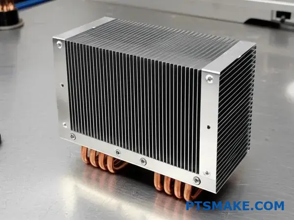
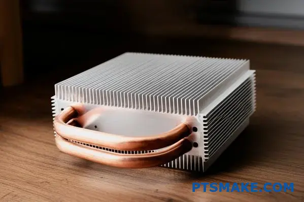
Embedded Base Plate Configurations
For industrial applications, we often recommend embedding the pipe into a copper or aluminum base. We machine a precise groove into the block.
The pipe is then soldered or epoxied into this groove. This protects the pipe from mounting pressure.
It acts as a heat spreader before the energy reaches the pipe. This is ideal for concentrated heat sources.
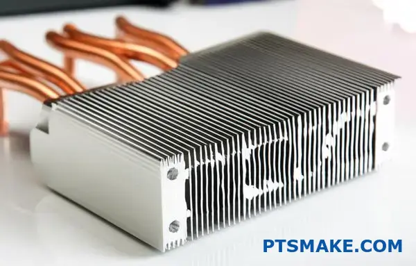
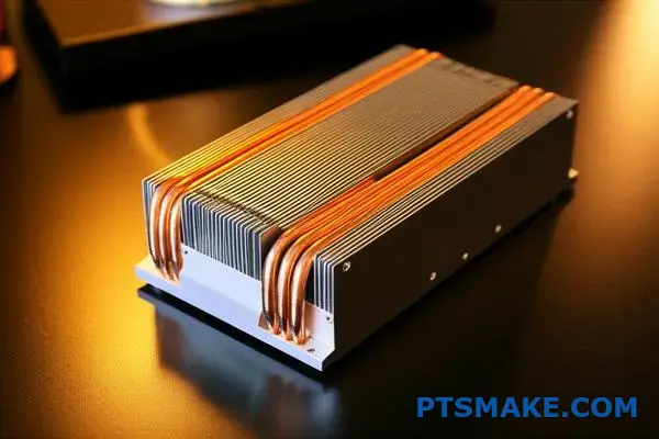
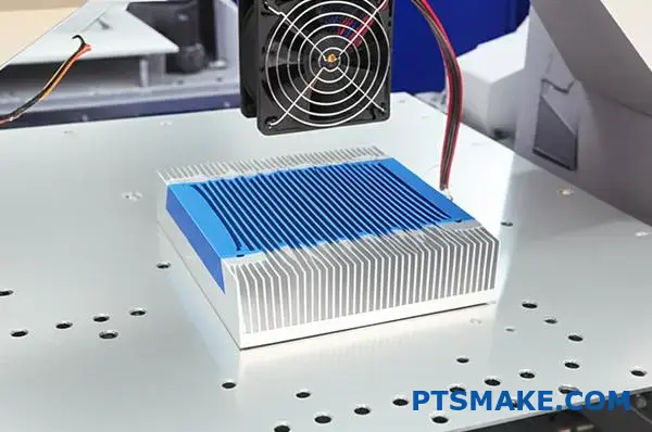
Tower and Remote Heat Sinks
In tight spaces, the heat pipe heat sink must move energy away from the source. Tower configurations lift the fin stack vertically.
This allows for larger fans and more surface area. The connection between the pipe and the fins is critical here.
We must pay close attention to contact resistance8 at every joint.
If the fit between the pipe and fins is loose, efficiency drops rapidly. We use tight tolerance stamping to ensure a snug fit.
| Feature | Direct Touch | Embedded Base | Tower Style |
|---|---|---|---|
| Thermal Path | Shortest | Intermediate | Extended |
| Mechanical Load | Low limit | High capacity | Variable |
| Cost Level | Low | Medium | High |
| Surface Finish | Difficult | Excellent | N/A (Base dependent) |
In summary, heat pipe assembly configurations range from cost-effective direct touch to robust embedded bases. Tower styles offer solutions for spatial constraints. Your choice must balance the thermal load, budget, and the structural integrity required by the final product design.
How do you select a heat pipe for an application?
Selecting the right heat pipe heat sink requires a structured approach. You cannot rely on assumptions or guesswork.
First, quantify the total heat load in watts. This is the starting point for every thermal design.
Next, identify the source and ambient temperatures. This dictates the working fluid, usually water for electronics.
Finally, measure the physical distance available. The heat must move efficiently from the source to the sink.
| Step | Parameter | Why it Matters |
|---|---|---|
| 1 | Heat Load (Q) | Determines the required pipe diameter and quantity. |
| 2 | Temperature Range | Selects the fluid (e.g., water vs. methanol). |
| 3 | Transport Length | Affects the total thermal resistance of the module. |
| 4 | Interface Material | Ensures good contact between the pipe and the heat source. |
After defining the basic thermal load, we must look at physical constraints. Space is often the hardest challenge in hardware design.
You might need to flatten the pipe to fit tight spaces. However, flattening reduces the maximum heat carrying capacity.
We calculate this reduction percentage carefully. This ensures the device remains safe even under peak load.
Orientation is the next critical check. Does the heat need to move vertically against gravity?
If the heat source is located above the cooling fin, gravity opposes the fluid return.
In this case, a sintered powder wick is mandatory. It possesses a high capillary lift to overcome gravity.
Grooved wicks are cheaper but only work well horizontally. We generally avoid them in complex 3D layouts.
In past projects, we noticed that selecting the wrong wick is a common cause of failure.
Material compatibility is also vital for long-term reliability. The fluid must not react chemically with the container wall.
Water and copper are the gold standard for electronics. They are reliable, conductive, and cost-effective.
Finally, you must consider the internal vapor pressure9 limits.
If the pressure exceeds the design limit, the pipe may deform. If too low, it limits power transfer.
| Constraint | Key Consideration | PTSMAKE Insight |
|---|---|---|
| Geometry | Bending Radius | Keep radius > 3x diameter to avoid kinking. |
| Orientation | Against Gravity | Sintered wicks are required for anti-gravity performance. |
| Cost | Manufacturing | Standard 6mm or 8mm tubes are 20% cheaper. |
To select the ideal heat pipe, start by defining the heat load and temperature range. Then, evaluate physical limitations like bending and orientation. Finally, ensure the internal pressure and wick structure align with your design goals to create an efficient heat pipe heat sink.
What are the design trade-offs in heat sink development?
Designing the perfect thermal solution is never a straight line. It is always a balancing act.
At PTSMAKE, we often see engineers struggle with conflicting goals. You want high performance, but you have a tight budget.
You need a compact size, but physics demands surface area. Let’s look at the core conflicts we face daily.
The Core Conflict Matrix
| Priority | Usually Sacrifices | Why? |
|---|---|---|
| High Performance | Low Cost | Requires copper or heat pipes. |
| Compact Size | Heat Dissipation | Less surface area available. |
| Low Weight | Durability | Thinner fins are fragile. |
We need to navigate these compromises carefully.
What are the design trade-offs in heat sink development?
When integrating a heat pipe heat sink, the variables multiply significantly.
In past projects at PTSMAKE, we found that adding heat pipes isn’t a magic fix. It adds complexity to the manufacturing process.
Balancing Performance and Cost
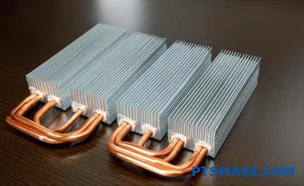
Copper offers superior conductivity. However, it is heavy and expensive compared to aluminum.
A hybrid approach often works best. We embed copper heat pipes into an aluminum base to balance weight and thermal transfer.
The Reliability Factor
We must also consider the wick structure10 inside the pipe. This dictates longevity and performance.
Sintered powder is durable but costly. Grooved interfaces are cheaper but sensitive to gravity.
Decision Matrix for Hardware VPs
Here is how we help clients decide based on specific project constraints.
| Feature | Performance Impact | Cost Implication | Ideal Use Case |
|---|---|---|---|
| Sintered Heat Pipe | High (Any Orientation) | High | Robotics, Aerospace |
| Grooved Heat Pipe | Medium (Gravity Sensitive) | Low | Stationary Electronics |
| Solid Copper Base | High | Medium-High | High-Power Servers |
| Aluminum Fin Stack | Medium | Low | Consumer Devices |
Making the Final Call
You cannot have it all. Prioritize your thermal resistance targets first. Then, fit the geometry into your mechanical envelope.
We explored the delicate balance between thermal performance, cost, and physical constraints. By using a strategic decision matrix, we can select the right materials and heat pipe configurations. This ensures the heat sink meets technical specifications without exceeding the project budget.
How does altitude affect a forced convection heat sink design?
Understanding Air Density Drops
When designing thermal solutions for high-altitude environments, standard calculations often fail. As altitude increases, air density decreases significantly compared to sea level.
This physical change directly impacts forced convection. A fan moves the same volume of air, but the actual air mass flowing over the fins is reduced.
| Altitude (ft) | Air Density Ratio | Cooling Impact |
|---|---|---|
| 0 (Sea Level) | 1.00 | Baseline |
| 5,000 | 0.86 | Reduced |
| 10,000 | 0.74 | Critical |
This reduction compromises heat transfer efficiency. We must account for this density shift in the initial design phase at PTSMAKE to ensure reliability.
Compensating for Lower Density
To maintain the performance of a heat pipe heat sink, we cannot rely on sea-level specifications. The lower air density means fewer air molecules strike the heat sink surface to carry thermal energy away.
Adjusting Fan Speed
The most direct solution is increasing fan speed. By boosting the RPM, we push more air volume to compensate for the lower mass. However, this increases noise and power consumption.
| Strategy | Pros | Cons |
|---|---|---|
| Higher RPM | No dimensional changes | Higher noise/power |
| Larger Fins | Passive improvement | Increased weight/size |
Modifying Fin Geometry
Alternatively, we can modify the heat sink structure. Increasing the total surface area helps regain lost thermal performance without altering the fan.
In past projects at PTSMAKE, we often increased fin height or density to offset the drop in the Nusselt number11. This ensures adequate heat dissipation even in thin air.
The Design Trade-off
You must balance these factors carefully. Simply making the heat sink larger might violate weight constraints in aerospace applications.
For a standard heat pipe assembly, a 15% to 20% increase in surface area is often required for operation at 5,000 feet to match sea-level thermals.
High altitude reduces air density, significantly diminishing the cooling capacity of forced convection systems. To prevent overheating, engineers must either increase fan speed to boost mass flow or expand the heat sink surface area to compensate for the reduced heat transfer efficiency.
Let PTSMAKE Power Your Next Heat Pipe Heat Sink Project
Ready to solve your most challenging thermal management needs? Partner with PTSMAKE for high-precision, custom heat pipe heat sink solutions. Contact us today for a fast, detailed quote—our engineering team is standing by to deliver superior performance, quality, and reliability for your application!

Click to understand how this energy value directly dictates the maximum power handling of your thermal design. ↩
Click here to understand how this physical property allows massive energy transfer without significant temperature rise. ↩
Click here to understand how high-speed vapor disrupts liquid flow and impacts total heat transport capacity. ↩
Click here to understand how phase changes absorb massive energy without rising temperatures, boosting cooling efficiency. ↩
Click to understand how pressure directly dictates the specific temperature at which a liquid turns into vapor. ↩
Click to understand how this phase-change mechanism maximizes cooling efficiency in high-precision thermal components. ↩
Learn how gas generation leads to heat pipe failure and how to detect it early in designs. ↩
Click here to learn how microscopic gaps at assembly interfaces block heat flow and how we minimize them. ↩
Click to learn how internal pressure variance impacts thermal transfer rates and safety limits. ↩
Click here to understand how different internal capillary structures affect heat pipe efficiency and gravity performance. ↩
Click here to understand how this dimensionless number quantifies the ratio of convective to conductive heat transfer. ↩