
A clear acrylic block can become difficult to inspect after machining and assembly. Vague transparency requirements leave buyers with costly disputes and unusable viewing areas.
Quick answer: You can specify acrylic manifold clarity through viewing tasks, marked zones, material grade, and inspection conditions. Both sides should agree on samples and finish limits. The team should then verify visibility after assembly, cleaning, and fluid exposure, and assess sealing and structural requirements separately.
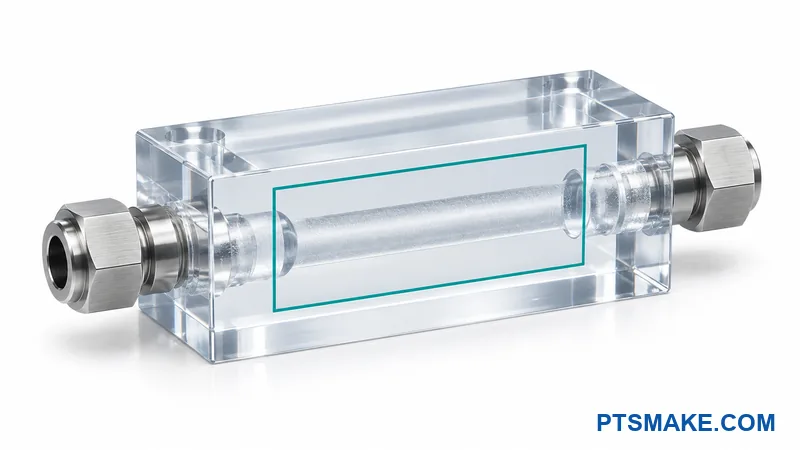
A useful drawing tells the supplier what must remain visible and how you will judge it. The steps below connect that requirement to channel geometry, finish choices, first-article checks, and a complete quotation brief.
You can share your manifold drawing and viewing requirements for review.
Define Acrylic Manifold Clarity by Viewing Task
State What the Operator or Sensor Must See
The first question is not how shiny the part should look. The first question is what someone must see through it. A viewing area used to spot a trapped bubble may need different acceptance conditions from a camera window.
The product team should identify the target, its location, and the decision that depends on seeing it. The target may be a liquid boundary, a bubble, a color change, or a feature used by a sensor. The drawing should connect the required view to a named operating task.
I would describe that task before choosing a finish label. Words such as “clear” and “optical” do not tell a supplier which details must remain visible. A task-based requirement gives both sides a reason for accepting or rejecting the appearance.
The following examples show the distinction. They are planning examples, not standard acceptance limits.
| Viewing task | What the team needs to define | What a clear-looking part cannot prove |
|---|---|---|
| Bubble observation | Target bubble size, channel location, background, and viewing state | The absence of bubbles outside the inspected region |
| Liquid-level or interface observation | Required boundary position and viewing direction | Actual flow rate through a clear, stationary-looking liquid |
| Color comparison | Reference color, illumination, fluid path, and comparison method | A reliable color decision under every light source |
| Contamination observation | Relevant target type, size, location, and detection method | Fluid cleanliness below the method’s detection capability |
| Camera or sensor view | Actual device, target, alignment, and usable image criteria | Sensor performance from visual appearance alone |
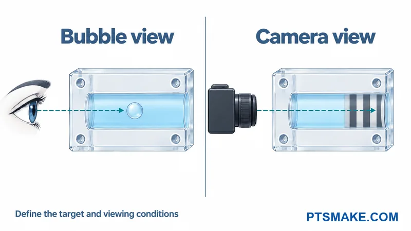
A transparent channel may help an operator observe a process. It does not replace a flow measurement, particle measurement, or other required instrument. The design team should state whether the view is an aid or part of a defined detection function.
Mark the Complete Viewing Path on the Drawing
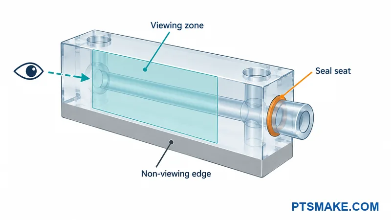
The drawing should mark the observer or sensor position, the target channel segment, and the faces between them. The viewing requirement applies to this complete path. A polished outer face does not establish the finish or visibility of the channel wall behind it.
Each viewing zone should have an identifier that appears in the drawing and inspection plan. The detail should show the zone boundary and the intended direction of observation. A general note saying “all surfaces transparent” gives little help when different surfaces serve different purposes.
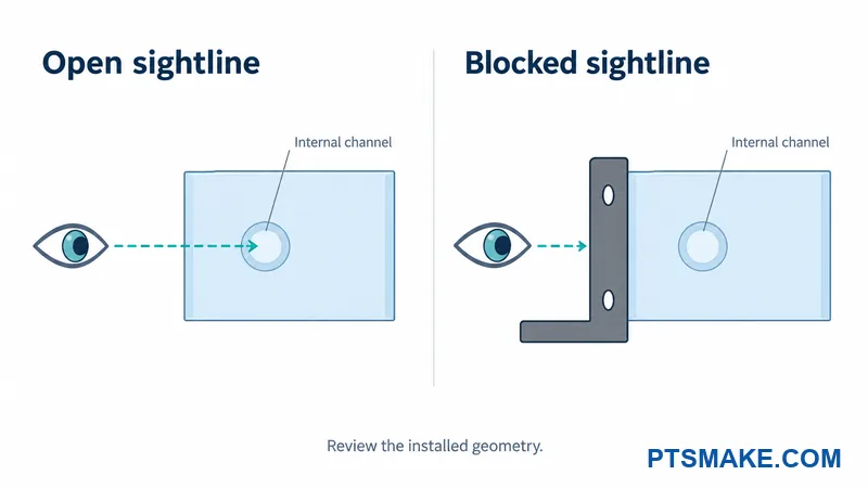
The zone map should also show nearby fittings, clamps, labels, and covers. These items may block a useful view after installation. A loose part inspected on a bench can offer access that the finished product does not provide.
Separate Viewing Faces from Sealing and Hidden Faces
The design engineer should identify sealing faces, port seats, and locating surfaces as separate functional zones. Their geometry and surface condition need their own requirements. A visual finish request should not quietly authorize changes to a seal seat or a locating edge.
Hidden or non-viewing surfaces can have different appearance limits if their other requirements permit it. This distinction gives the supplier a clear basis for separating necessary finishing from optional cosmetic work. It also helps quality staff apply the correct rule to each area.
Define the Part’s State During Observation
The inspection plan should state whether the manifold is dry, filled, cleaned, or fully assembled. It should identify the intended fluid or an approved representative medium. Those conditions belong to the viewing requirement because the same part may look different in another state.
The team should also state whether the view is needed before installation, during normal use, or during service. Each required state needs suitable evidence. A photograph from one convenient angle should not become the only basis for approval.
Confirm PMMA Grade and Service Conditions
Request Evidence for the Actual Stock
PMMA is the material family commonly called acrylic. The buyer should specify the required stock grade or define how the supplier can propose an alternative. The quotation should identify the manufacturer, grade, stock form, and relevant material documentation.
An acrylic sheet specification1 can help define purchased sheet. ASTM D4802 covers general-purpose methacrylate sheet; it does not certify a finished manifold for a particular fluid system. The engineer should check whether a proposed specification fits the actual stock and application.
Raw-stock optical data describe the material under stated measurement conditions. They do not establish the view through a drilled channel, a finished port, or an assembled block. The supplier should connect its material evidence to the grade and thickness actually being quoted.
The broader acrylic CNC machining considerations provide background for a design discussion. The manifold still needs its own viewing and service requirements. General material or machining advice should not replace that review.
List Every Fluid and Cleaning Exposure
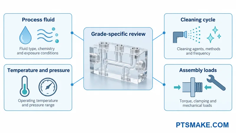
The buyer should provide the process fluid, concentration, possible additives, and cleaning method. The review should also include residues from assembly, sealants, lubricants, and materials that touch the viewing area. These details help the responsible engineer assess the actual exposure.
Chemical resistance2 depends on the particular material and chemical. PLEXIGLAS guidance distinguishes its grades and identifies substances that can damage them. That guidance does not establish compatibility for an unspecified manifold under load.
The service brief should include temperature, pressure or vacuum conditions, exposure duration, expected cycles, and intended service life. The buyer should identify which conditions occur together. A short room-temperature contact check is different from repeated cleaning of an assembled part in service.
Treat Material Data as Starting Evidence
The material supplier’s recommendations should inform the test plan for the specified grade. The product’s engineering owner should decide what additional evidence is needed for the application. A general compatibility chart cannot close every question about assembly stress, sealing, and service life.
If PMMA cannot meet the combined requirements, the team should review the material or product concept before fixing the finish specification. An alternative may change visibility, geometry, cost, and joining options. The buyer should approve those trade-offs instead of accepting an undocumented substitution.
Review Channel Sightlines and Port Loads Before Finishing
Check the Actual Geometry and Installed Access
The supplier needs the CAD model and the viewing-zone drawing together. The model shows the channel geometry; the drawing explains what that geometry must let the user see. Neither document fully replaces the other.
The review should cover channel depth, channel crossings, local wall thickness, and the path between the target and observer. A nearby channel or curved surface may make a feature harder to distinguish. The team should evaluate the actual view instead of assuming that clear stock removes every optical obstacle.
The model should include the surrounding hardware when it affects access. A mounting bracket, cable, fitting, or label can cover a viewing zone. The design should also leave practical access for the intended inspection or cleaning method.
The supplier should identify which surfaces it can reach for the proposed finish. An accessible exterior face and a deep internal bore present different finishing conditions. The quote should state where the proposed outcome depends on a sample trial.
The required view also depends on the application. The discussion of transparent manifold applications in rail equipment provides one sector-specific context. A different product needs its own service conditions, access requirements, and acceptance plan.
Use a Representative Sample When the View Is Uncertain
I would request a sample that contains the difficult viewing path, not just a polished flat coupon. The sample should represent the relevant thickness, channel position, internal surface condition, and finish. It should also include nearby hardware if that hardware affects the view.
A simple coupon can answer a limited material or finish question. It cannot prove visibility through a geometry that it does not contain. The sample request should state which question the sample will answer and which questions remain open.
A different channel route or construction method may improve access. It may also change sealing, cleanliness, strength, or inspection needs. The design owner should approve the complete trade-off before the supplier changes the manufacturing route.
Review Tapped Ports, Fittings, and Seals Together
The fitting schedule should identify the actual connection, seal arrangement, and installation method. The supplier should not infer these details from a nominal hole size. The drawing and assembly instructions need to describe the same interface.
The PLEXIGLAS joining guide warns about stress from screw connections and cut threads3. It advises against cutting threads in its sheet context because the resulting stress can be underestimated. That warning deserves review when a design proposes tapped acrylic ports.
The guide is not a manifold-specific port standard. The buyer should request advice for the chosen grade, geometry, fitting, seal, and duty. Direct threads, inserts, and other connections each need an approved design; none should be presented as a universal solution.
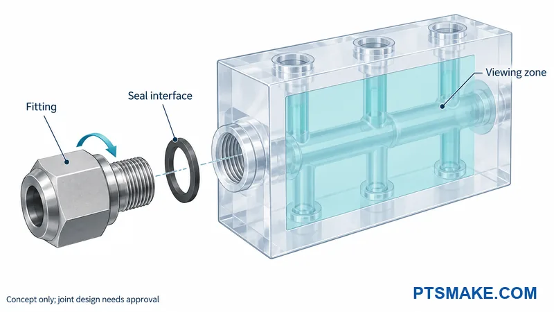
The illustration shows one possible arrangement only. It does not prescribe a thread form, seal type, or installation torque.
The assembly review should include fitting weight, attached tubing, external loads, and expected connection cycles. The design team should state whether a port is assembled once or repeatedly opened during service. The selected interface must address those conditions.
The quality plan should distinguish permitted surface marks from suspect cracks or crazing near a port. A cosmetic reference sample does not make a structural defect acceptable. The responsible engineer should define how questionable indications are handled.
A representative assembled first article should receive both the required viewing check and the agreed leak or pressure assessment. The buyer and supplier should settle the method and acceptance criteria before the sample is built.
Select a Finish for Each Functional Surface
Compare the Result Before Choosing the Process
A finish label should describe the required outcome at a named location. The supplier can then propose a process that suits its equipment, the material, and the geometry. The buyer should approve the result through an agreed sample or suitable measurement.
The following categories are descriptive examples, not standardized optical grades.
| Finish goal | Intended use | Evidence to request | Quotation issue to separate |
|---|---|---|---|
| As-machined surface | No required view through that zone, subject to its other functions | Agreed surface appearance and functional checks | Base machining and any required edge treatment |
| Visibly transparent face | A defined human observation task through an accessible area | A representative sample viewed under agreed conditions | Finishing area, access, handling, and inspection |
| Local optical window | A defined camera or sensor viewing path | Evidence using the specified device or an approved method | Local finishing, optical verification, and protection |
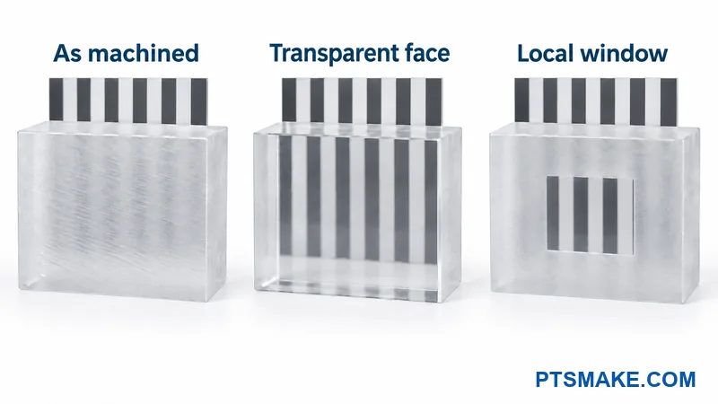
The finish comparison should cover the entire viewing path. A clear front face does not establish the appearance of a drilled bore. The supplier should identify any internal surface that remains as machined and explain how it affects the proposed viewing task.
Protect Dimensions and Adjacent Functional Areas
The material manufacturer’s edge and surface finishing guidance4 describes several finishing outcomes. It also warns that excessive heat and some finishing operations can introduce stress. These points support a process review, not a single polishing recipe for every manifold.
The drawing should state which dimensions and surface conditions apply after finishing. The supplier should explain how it will protect seal seats, port details, and locating features. A visually improved part can still be unacceptable if finishing changes a required interface.
The buyer should ask how the supplier will confirm that the proposed finish is repeatable. Useful evidence includes a representative sample, a defined process scope, and a practical inspection method. A generic photograph of a polished sheet does not answer a difficult channel question.
The quote should separate base machining from optional finishing and additional validation. The supplier should state any sample work, extra handling, or inspection that affects cost and lead time. The buyer can then compare offers that address the same requirement.
You can include marked viewing zones and your preferred reference sample with your enquiry.
Make Clarity an Acceptance Standard
Agree on a Reference and a Repeatable View
The buyer and supplier should agree on what counts as an acceptable view before production. The acceptance record should identify the viewing zone, target, part state, and inspection method. The record should also name the person who can approve borderline results.
A master sample can make a visual requirement easier to understand. Both sides should identify its revision and the condition that it represents. A reference from a different grade, thickness, or channel geometry may not represent the part being ordered.
A sample pair may be more useful than one ideal sample. The team can retain an acceptable boundary example and a rejected example when that distinction is practical. Any examples must come from the agreed review; a generated illustration cannot serve as physical acceptance evidence.
The inspection setup should define illumination, background, viewing direction, distance, and permitted aids. The team should state whether the observer may rotate the part or change the angle. Otherwise, one person may approve a feature that another cannot see under the intended conditions.
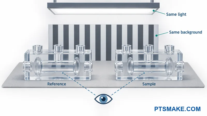
The setup should include the actual camera or sensor when its output drives acceptance. A human observer and an imaging device may respond differently to reflections, contrast, and distortion. The acceptance method should follow the intended task.
Define Defect Limits by Zone
The quality team should define the relevant defect types in plain language. These may include visible tool marks, scratches, haze, polishing marks, or contamination on the inspected surface. The agreement should explain which indications require cleaning, further review, or rejection.
A defect’s location can matter as much as its appearance. A mark outside the viewing path may be acceptable while a similar mark hides the target. The plan should connect each limit to the zone and task instead of applying one vague appearance rule everywhere.
| Acceptance item | What the agreement should record |
|---|---|
| Viewing function | Target, relevant location, and required observation or device output |
| Sample identity | Part number, revision, material, finish, and approval owner |
| Viewing setup | Light, background, direction, distance, and allowed aids |
| Inspection state | Cleanliness, masking removal, fluid state, fittings, and assembly condition |
| Defect decision | Zone-specific limits and the route for uncertain indications |
| Traceability | Sample or batch identification, inspection result, and any approved deviation |
Photographs can support a record if the lighting, angle, and part state are identified. They should not silently replace an agreed physical comparison or measurement. Camera exposure and image processing can also change the apparent visibility of a mark.
Use ASTM D1003 Where Its Scope Fits
Haze and luminous transmittance5 are different properties. ASTM D1003 provides methods for suitable planar transparent-plastic specimens. Its public scope describes haze and transmittance measurement; it does not set a universal acceptance limit for a finished acrylic manifold.
A test laboratory should confirm whether the proposed surface or specimen fits the method. A curved internal channel or thick complex assembly should not automatically receive a flat-sheet interpretation. The buyer should agree on specimen preparation and how the result relates to the finished viewing task.
A flat witness coupon can provide useful process or material evidence. It does not reproduce every internal surface, fitting load, or optical path in the manifold. The acceptance record should keep that limitation visible.
Decide Who Resolves Uncertain Results
I would agree on the escalation route while the sample is being approved. The supplier should know who can accept a deviation and which evidence that person needs. The record should state whether an approval applies to one part, one batch, or a revised requirement.
A supplier should not repair a borderline viewing area without understanding the effect on dimensions and other functions. The buyer should define when rework needs approval and which checks must be repeated afterward. The final decision should refer to the actual part and its condition.
Validate the Assembled and Exposed First Article
Start with a Defined Build Record
The first article should represent the intended production material, geometry, finish, fittings, seals, and assembly method. The build record should identify their revisions. A clear display sample with different interfaces cannot answer every question about the intended product.
The buyer should name the engineering and quality owners for the validation plan. These owners should define the questions, conditions, sequence, and acceptance criteria before testing starts. The machining supplier needs to know which checks it performs and which checks belong to another party.
A baseline viewing check should record the condition after the specified finishing and cleaning steps. The record should identify any marks already present. This baseline helps the team distinguish an existing indication from a change that appears later.
The plan should state whether tests use the same sample or separate representative samples. The sequence can affect the result, so the report should record the actual order. A test completed on an earlier condition should not be described as evidence for a later condition without justification.
Check the Part After Fitting Installation
The assembled check should use the approved fitting and seal arrangement. The assembly record should identify the installation instructions and any required controls. The drawing alone cannot show whether the first article was assembled as intended.
The observer should repeat the required viewing task in the assembled state. The check should include access around fittings, brackets, and tubing where those items affect the view. It should also record any new whitening, cracking, crazing, or distortion that needs engineering review.
The team should assess sealing and pressure-related requirements separately from appearance. A visible channel does not prove a leak limit, pressure rating, or service life. The responsible engineer should define the appropriate method, conditions, and acceptance criteria for the intended duty.
The record should distinguish a visual result from a leak or structural result. A passing result in one column should not automatically approve the other. Any failed or uncertain result needs a documented decision before the design is released.
Include Relevant Cleaning and Fluid Exposure
The material review should consider crazing associated with stress and chemical exposure6. Plaskolite illustrates that interaction in a technical bulletin about continuous-cast acrylic. Its examples support reviewing combined conditions, not predicting the outcome of every PMMA manifold.
The validation plan should identify the actual cleaner or approved representative, concentration, temperature, contact time, and relevant cycles. It should also state whether the part is loaded or assembled during exposure. The team should justify any substitute fluid or shortened test.
The operator should follow the agreed cleaning, rinsing, and drying sequence. A different cleaner or an extra polishing step changes the condition being evaluated. The report should record such deviations rather than presenting them as the approved process.
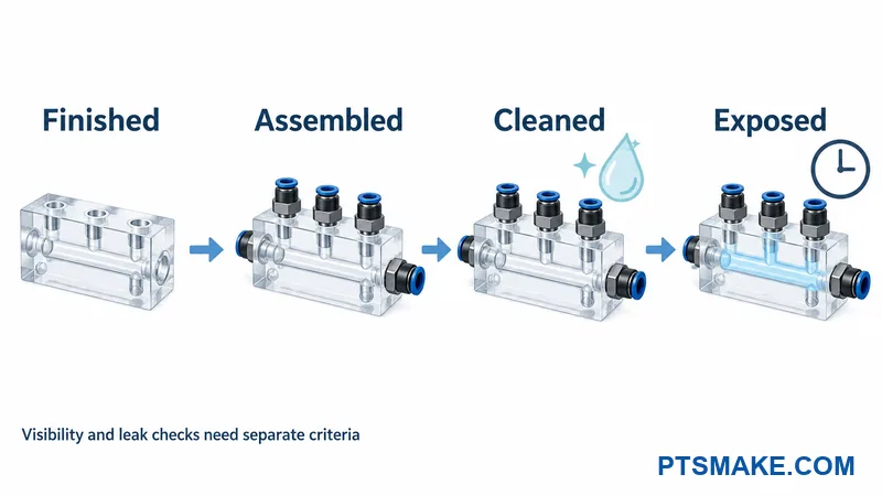
Record What Each Check Establishes
The following record separates the viewing question from other product requirements. The project team supplies the actual methods and limits.
| Checkpoint | Viewing evidence | Separate functional evidence |
|---|---|---|
| Finished baseline | Agreed view and existing surface indications | Dimensions and specified surface features |
| Assembled condition | Access, target visibility, and new indications near interfaces | Assembly record and agreed sealing or pressure assessment |
| Approved cleaning | View after the stated cleaning and drying sequence | Any required residue or cleanliness assessment |
| Relevant fluid exposure | View and material condition after the specified exposure | Required sealing, dimensional, or mechanical reassessment |
The validation owner should state what remains outside the evidence. A short first-article trial may answer a finish question without establishing long-term service life. The release decision should match the scope of the work actually performed.
Send a Quote-Ready Clarity Brief
Give Suppliers the Same Requirements
A complete RFQ lets suppliers quote the same viewing task and acceptance conditions. The buyer should send the current 3D model, controlled drawing, and zone map together. The package should identify any unanswered question that needs supplier feedback.
The brief should include the following inputs. The buyer can mark an item as unresolved and request a proposal instead of leaving the requirement unstated.
| RFQ input | Information the supplier needs |
|---|---|
| Part definition | Model, drawing revision, quantity, and relevant assembly view |
| Material | Required PMMA grade, stock form, evidence, and substitution approval route |
| Viewing task | Target, viewing zones, direction, installed access, and inspection state |
| Interfaces | Ports, fittings, seals, nearby hardware, and assembly or service cycles |
| Service conditions | Process fluid, cleaner, concentration, temperature, pressure, and exposure profile |
| Finish and acceptance | Zone-specific outcome, reference sample, inspection method, and decision owner |
| Validation scope | Representative sample requirements, assigned tests, records, and release criteria |
| Delivery protection | Approved cleaning state, surface protection, packaging, and identification |
The overview of custom manifold requirements provides a service context for the enquiry. The quote should still state whether the proposed material, geometry, finish, and validation work are included.
Separate Base Work from Additional Evidence
The quotation should distinguish machining from finishing, sample trials, and additional verification. Each item should have a clear scope and owner. A lower price is difficult to assess if one offer excludes internal-channel finishing or the required sample checks.
The supplier should state any assumption behind its quotation. Examples include an accessible viewing face, a customer-supplied reference, or validation performed by the buyer. The buyer should resolve those assumptions before treating the offer as a complete production commitment.
Protect the Approved Appearance Between Batches
The delivery requirements should address contact with packaging, protective films, and handling materials. These materials need compatibility review where they touch the acrylic. The supplier should identify the condition in which the part will arrive and how any protection should be removed.
The repeat-order record should preserve the approved grade, finish scope, reference sample, and inspection conditions. Changes to material, fitting, cleaner, or finishing route should receive the relevant review. A retained sample and a controlled drawing give both sides a stable basis for that decision.
Discuss Your Acrylic Manifold Viewing Requirements
You can send your model, viewing zones, PMMA grade, fluid and cleaning conditions, fitting details, and quantity. Your enquiry can ask PTSMAKE to review the quotation scope and identify finish or validation questions that need representative samples.

ASTM D4802 is a general acrylic-sheet specification. Its public scope does not establish the suitability of a machined manifold for a specific fluid or viewing task. ↩
Chemical resistance describes how a material responds to a particular exposure. Grade-specific guidance still needs review against the actual service conditions. ↩
The PLEXIGLAS joining guide discusses screw loads and cautions against cut threads in its sheet applications. Its guidance is a reason for interface review, not a manifold port specification. ↩
The ACRYLITE finishing guide describes surface and edge treatment and associated stress concerns. It does not guarantee access or clarity inside a complex channel. ↩
Haze concerns light scattering, while luminous transmittance concerns transmitted light weighted for human vision. ASTM D1003 applies to suitable planar specimens and does not define this manifold’s acceptance limits. ↩
Crazing appears as a network of fine cracks. The Plaskolite bulletin explains stress and chemical exposure in its continuous-cast acrylic context. A different grade or assembled manifold needs its own application review. ↩