Struggling with inconsistent weld strength, cosmetic defects, or high reject rates in your ultrasonic plastic welding operations? You’re not alone – these challenges plague manufacturers daily, leading to production delays, increased costs, and frustrated engineering teams trying to meet tight specifications.
Ultrasonic plastic welding is a precise joining method that uses high-frequency vibrations to create molecular bonds between thermoplastic parts through controlled heat generation at the joint interface, offering fast cycle times and strong, reliable bonds when properly optimized.
At PTSMAKE, I’ve worked with countless clients who initially thought their welding issues were equipment problems, only to discover the root causes lay in joint design, material selection, or process parameters. This comprehensive guide covers 17 critical aspects of ultrasonic welding that separate successful operations from struggling ones.
What defines a plastic’s ‘weldability’ from a material science perspective?
Not all plastics are created equal for welding. Success in ultrasonic plastic welding hinges on material science. It’s about understanding a polymer’s core properties.
Molecular Structure Matters
Plastics are either amorphous or semi-crystalline. This structure dictates how they react to heat and vibration. It’s the first thing we check at PTSMAKE.
| Structure | Welding Ease | Example |
|---|---|---|
| Amorphous | Easier | ABS, PC |
| Semi-Crystalline | Harder | PP, Nylon |
This fundamental difference has huge implications. It directly impacts joint design and process parameters.
Let’s go deeper. Beyond structure, other factors are critical for a strong, reliable weld. These properties don’t exist in isolation; they interact. A mismatch here often leads to weak bonds or component failure.
Melt Temperature & Flow
A plastic’s melt temperature must be reached. But a wide melting range can be tricky. It demands very precise control over the ultrasonic process. The goal is efficient energy transfer to the joint interface.
The Role of Stiffness & Friction
Stiffness, measured by the modulus of elasticity1, is vital. Stiffer materials transmit ultrasonic vibrations more effectively. Softer, more flexible plastics can dampen the energy before it creates a melt.
A high coefficient of friction is also beneficial. It helps generate heat quickly right where it’s needed. Materials with low friction require more energy or time.
In our work, we’ve found these factors interact in complex ways. Analyzing these properties is a key step in our process.
| Property | High Value | Low Value |
|---|---|---|
| Stiffness | Good energy transmission | Poor energy transmission |
| Friction | Faster heat generation | Slower heat generation |
A plastic’s weldability is defined by its molecular structure, melt temperature, stiffness, and friction. Understanding these interconnected properties is fundamental for successful component design and achieving strong, reliable ultrasonic welding results.
What are the three primary welding modes: time, energy, and distance?
In ultrasonic plastic welding, control is everything. The process happens in fractions of a second. So, how do we ensure a perfect weld every time? The answer lies in the welding modes.
These modes are simply the parameters we use to tell the machine when to stop. Each one offers a different way to control the welding cycle. They ensure consistency and quality.
Choosing Your Control Method
Think of it as a trigger for stopping the process. Each mode—time, energy, or distance—acts as that signal. Choosing the right one depends on your parts and goals.
| Mode | Control Principle | Best For |
|---|---|---|
| Time | Fixed duration of ultrasonic vibration | Simple, highly consistent parts |
| Energy | Specific amount of energy delivered | Parts with slight variations |
| Distance | A precise amount of material collapse | Critical assembly dimensions |
Choosing the right welding mode is critical. It directly impacts the final weld quality, strength, and consistency. Each mode has its place, and understanding their differences is key for any project. In past PTSMAKE projects, selecting the mode is one of the first things we discuss with our clients.
Time Mode: The Simplest Approach
This mode runs the ultrasonic vibrations for a preset time. It’s simple to set up and works well when parts are extremely consistent. However, it cannot compensate for variations in part geometry or material. This can lead to overwelding or underwelding.
Energy Mode: A Smarter Control
Energy mode measures the energy delivered to the part. The weld cycle stops once a specific energy value is reached. This method adapts to small part variations. It ensures each part receives the same amount of energy for melting. This is because the process relies on Hysteresis heating2 to generate melt. More material requires more energy.
Distance Mode: Ultimate Precision
Distance mode stops the weld based on how much the parts have collapsed. This can be a "collapse distance" (the amount of melt) or an "absolute distance" (the final part height). It offers the highest precision for final assembly dimensions. But, it is very sensitive to part tolerance variations.
| Mode | Advantages | Disadvantages |
|---|---|---|
| Time | Easy to set up; fast cycle times. | Inconsistent welds if parts vary. |
| Energy | Compensates for part variations; consistent weld strength. | Can be harder to dial in the initial settings. |
| Distance | High precision; ensures final dimensions. | Sensitive to part tolerances; requires precise fixtures. |
These three modes—time, energy, and distance—are the primary controls in ultrasonic welding. Each provides a different method to stop the weld cycle, offering unique advantages for specific applications, from simple to high-precision parts.
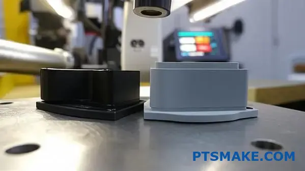
What are the main types of ultrasonic welding joint designs?
Choosing the right joint design is critical. It’s the first step to a successful weld. This design dictates how ultrasonic energy is focused. It ensures a strong, reliable bond.
At PTSMAKE, we focus on three primary designs. Each serves a different purpose. They are selected based on part geometry, material, and strength requirements.
A Quick Comparison
Here’s a simple breakdown of the main types. We’ll explore each one in more detail.
| Joint Type | Primary Advantage | Common Use Case |
|---|---|---|
| Butt Joint with Energy Director | Precise energy focus | General purpose, electronic housings |
| Shear Joint | Strong, hermetic seals | Medical devices, containers |
| Scarf Joint | Excellent alignment | Cylindrical or aligned parts |
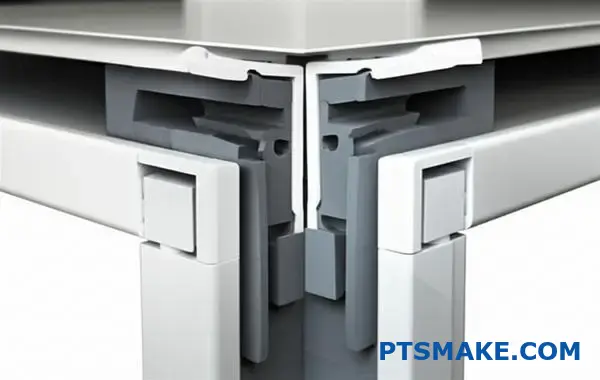
Butt Joint with Energy Director
This is the most common design we see. The key is the "energy director." It’s a small, molded triangular ridge on one of the parts. This ridge concentrates the ultrasonic energy. It initiates a rapid, controlled melt.
Ideal Application
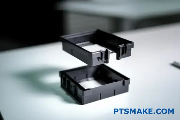
Butt joints are perfect for parts made from amorphous plastics. Think of housings for consumer electronics or automotive components. They work best when hermetic seals aren’t the top priority. The joint provides good strength for many applications.
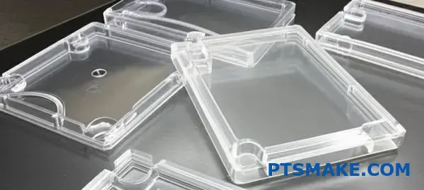
Shear Joint
When you need a strong, hermetic seal, the shear joint is often the answer. This design creates a bond by melting the surfaces as they rub against each other under pressure. This smearing action forces out air. It creates a leak-proof seal. The plastic’s viscoelastic3 nature is crucial here.
At PTSMAKE, for parts requiring a tight seal, like fluid containers or medical devices, we often recommend this method. Based on our tests, shear joints can produce some of the strongest bonds in ultrasonic plastic welding.
Scarf Joint
The scarf joint is an excellent choice for self-alignment. The angled mating surfaces guide the two parts into position during welding. This is great for cylindrical parts or components where precise alignment is key. It also produces a clean joint line with minimal flash.
Choosing the right joint—butt, shear, or scarf—is crucial for success. Each design offers unique benefits for strength, sealing, and alignment. The final product’s quality and performance depend heavily on this initial design decision.
What is a system for classifying common ultrasonic welding defects?
To properly diagnose weld failures, you need a system. A clear framework helps us quickly find the root cause of a problem. It removes the guesswork from troubleshooting.
This systematic approach groups defects into four main categories. This organization makes the diagnostic process much more efficient for any team.
Here is a quick overview of these groups.
| Defect Category | Primary Indicator |
|---|---|
| Insufficient Weld | Weak or non-existent bond |
| Overwelding | Excess flash and material damage |
| Cosmetic Flaws | Unwanted marks or surface issues |
| Dimensional Issues | Changes in part shape or size |
This structure is the first step. It helps us build a logical troubleshooting plan.
This diagnostic framework is a practical tool. In our projects at PTSMAKE, we use it to streamline problem-solving with our clients. It creates a common language for identifying issues.
Insufficient Weld
This is the most common failure. It means the parts are not bonded correctly. The weld is weak or non-existent. Usually, this points to a lack of energy at the weld joint. It could be due to low amplitude or insufficient weld time.
Overwelding
This is the opposite problem. Too much energy is applied to the parts. You’ll see excessive flash pushed out from the joint. This can cause material degradation4. The plastic’s molecular structure breaks down, which severely weakens the final assembly.
Cosmetic and Dimensional Flaws
These defects impact the part’s appearance and fit. While the weld might be strong, these flaws can still lead to rejection. This is especially true for consumer-facing products where aesthetics are key.
Let’s look at a few examples.
| Flaw Type | Description |
|---|---|
| Marking | Scuffs or tool marks on the part surface from the horn. |
| Sinking | Depressions on the surface opposite the energy director. |
| Part Distortion | The overall geometry of the part is altered post-weld. |
Dimensional accuracy is critical in ultrasonic plastic welding. Even minor distortion can prevent parts from fitting correctly in a larger assembly, a challenge we often help solve.
This framework categorizes weld failures into four types: insufficient weld, overwelding, cosmetic flaws, and dimensional issues. Using this system simplifies diagnostics, leading to faster solutions and higher quality control. It is a foundational tool for repeatable success.
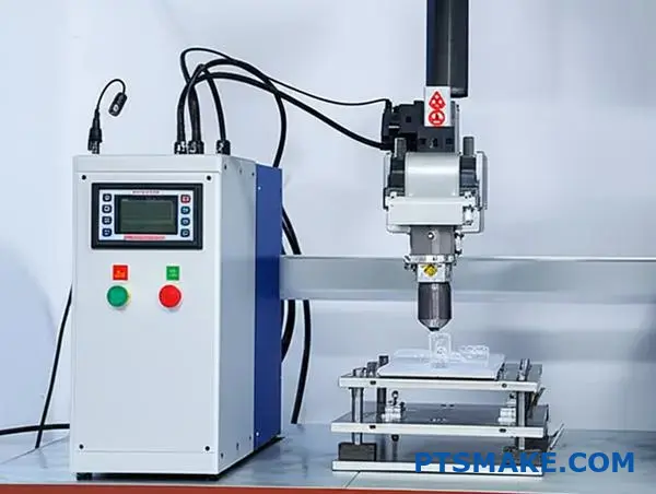
What different types of ultrasonic welding equipment exist and their applications?
Choosing the right ultrasonic welding equipment is vital. Your decision impacts efficiency, quality, and your bottom line. The landscape is primarily divided into three categories.
These are benchtop, automated, and hand-held welders. Each type is designed for different scales of production. They handle various part sizes and complexities. Let’s break them down.
| Equipment Type | Best For | Key Feature |
|---|---|---|
| Benchtop | Small to medium batches | Versatility |
| Automated | High-volume production | Consistency |
| Hand-held | Spot repairs, large parts | Portability |
Understanding these distinctions is the first step. It helps in making an informed investment for your assembly needs.
A Deeper Look at Equipment Applications
The choice of equipment goes beyond just production volume. It’s about precision and integration. In projects at PTSMAKE, we often guide clients on this. The goal is to match the machine to the specific application.
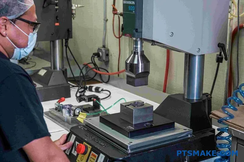
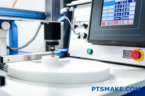
Benchtop Welders: The Versatile Workhorse
Benchtop welders are perfect for manual assembly stations. They are ideal for prototyping and low-to-mid volume runs. Operators have direct control over the process. This makes them great for intricate parts. They are common in medical device and electronics assembly.
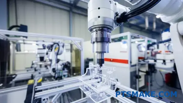
Automated Systems: The Engine of Mass Production
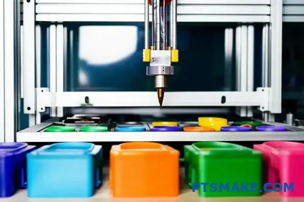
For high-volume manufacturing, automation is key. Automated ultrasonic plastic welding systems integrate directly into production lines. They ensure high-speed, repeatable welds with minimal human intervention. This technology is crucial for the automotive and consumer goods industries. A power supply sends a signal to a transducer. The transducer converts this using the piezoelectric effect5. This creates the necessary vibrations.
Hand-Held Welders: Flexibility in Your Palm
Hand-held units offer unmatched portability. They are used for spot welding, staking, and repairs. They are also excellent for large or hard-to-reach parts. You’ll find them in automotive repair and on-site fabrication tasks.
| Welder Type | Industry Application | Example Use Case |
|---|---|---|
| Benchtop | Medical Devices | Sealing sterile packaging |
| Automated | Automotive | Assembling dashboard components |
| Hand-held | Construction | Spot-welding large panels |
Selecting the right equipment type is critical. Benchtop units offer versatility, automated systems provide scale and consistency, while hand-held welders give you portability. This choice directly influences your production efficiency, quality control, and overall cost-effectiveness.
What are the key differences in welding rigid vs. flexible plastics?
Welding different plastics is not a one-size-fits-all process. The settings for rigid materials are very different from those for flexible ones. You must adjust your approach.
Getting this right ensures a strong, reliable weld. It prevents damage and weak bonds.
Parameter Adjustments for Rigid Plastics
Rigid, semi-crystalline materials like ABS or Polycarbonate need more energy. This means higher amplitude and greater force to melt their structured molecular chains effectively.
Settings for Flexible Plastics
Flexible, amorphous plastics like PVC or TPE require a gentler touch. Lower force and amplitude are key here. This prevents melting through or damaging the material.
Here’s a quick comparison based on our experience at PTSMAKE:
| Parameter | Rigid Plastics (e.g., ABS) | Flexible Plastics (e.g., TPE) |
|---|---|---|
| Amplitude | High | Low |
| Force | High | Low |
| Weld Time | Typically Shorter | Can Be Longer, Controlled |
The success of an ultrasonic plastic welding project hinges on precise parameter control. Each material class behaves uniquely under vibrational energy, and understanding this is critical.
Why Rigid Materials Need More Power
Rigid, semi-crystalline plastics have an ordered molecular structure. This structure requires significant energy to break down and melt. High force is needed to maintain contact and transmit vibrations efficiently. The high amplitude6 generates the necessary friction and heat quickly. Without enough power, you won’t achieve a proper molecular bond, leading to a weak or incomplete weld. In our work at PTSMAKE, we start with the material’s data sheet and then conduct tests to find the optimal high-energy window.
The Gentle Approach for Flexible Materials
In contrast, flexible, amorphous plastics have a random molecular structure. They soften over a wider temperature range and require much less energy to reach a welding state. Using high amplitude or force on these materials is a common mistake. It can easily cause the material to melt through, deform, or become brittle around the weld joint. We often use lower settings over a slightly longer, controlled duration. This allows the material to flow and bond without being destroyed.
This table shows the risks of incorrect settings:
| Material Type | Risk of Too Much Power | Risk of Too Little Power |
|---|---|---|
| Rigid | Material degradation, flash | No weld, weak bond |
| Flexible | Melt-through, deformation | Incomplete surface fusion |
In summary, rigid plastics need high-power settings to melt their structured forms. Flexible plastics require a lower-energy, more delicate approach to prevent damage. Tailoring the welding process to the material’s specific class is essential for a successful bond.
How do fillers and additives (e.g., glass, talc) impact welding?
Additives fundamentally change a plastic’s properties. This directly impacts how it behaves during welding. Some changes are beneficial, while others create significant challenges.
Understanding these effects is key to a successful weld.
The Impact of Reinforcing Fillers
Fillers like glass fiber and talc are common. They are added to increase stiffness and strength. This added rigidity can improve energy transmission during ultrasonic plastic welding.
However, these fillers are abrasive. They act like sandpaper on the welding equipment, causing premature wear.
| Additive Type | Primary Effect on Material | Impact on Welding |
|---|---|---|
| Reinforcing Fillers | Increases stiffness, strength | Mixed: Aids energy flow but causes tool wear |
| Plasticizers | Increases flexibility, softness | Negative: Dampens vibrations, weakens weld |
| Flame Retardants | Reduces flammability | Negative: Can interfere with bonding |
This requires careful balancing of material choice and process parameters.
When we talk about welding filled plastics, the conversation gets more complex. Each additive introduces unique variables that must be managed for a strong, reliable joint. It’s a critical consideration in part design.
Abrasive Fillers: The Trade-Off
Glass fibers and talc are excellent for creating rigid parts. During ultrasonic welding, this stiffness helps transmit energy efficiently to the joint interface. This can lead to faster weld times.
The problem is physical wear. These hard, sharp particles grind against the welding horn. This abrasive action shortens the tool’s lifespan, increasing operational costs. At PTSMAKE, we often advise clients on specific horn materials or coatings to mitigate this issue. This material property of viscoelasticity7 is crucial here.
Chemical Interference from Other Additives
Other additives can actively disrupt the welding process.
The Softening Effect of Plasticizers
Plasticizers make materials more flexible. This property is great for some applications but detrimental to ultrasonic welding. The softness dampens the high-frequency vibrations, preventing sufficient heat generation at the joint.
Flame Retardants and Contamination
Flame retardants are designed to activate with heat. Unfortunately, welding temperatures can trigger them. They might release gas or form a char layer at the interface, preventing the molten plastics from properly fusing.
| Additive | Specific Welding Challenge | Recommended Action |
|---|---|---|
| Glass Fiber | Causes significant horn wear | Use hardened tool steel or coated horns |
| Talc | Abrasive, can absorb energy | Adjust amplitude and weld pressure |
| Plasticizers | Dampens ultrasonic vibrations | Consider alternative welding methods |
| Flame Retardants | Can contaminate the joint interface | Test material compatibility thoroughly |
This makes material selection a critical first step for any project involving welding.
Fillers like glass can help energy transmission but cause horn wear. Meanwhile, additives such as plasticizers and flame retardants often interfere with the molecular bonding process, leading to poor weld quality and inconsistent results that must be managed carefully.
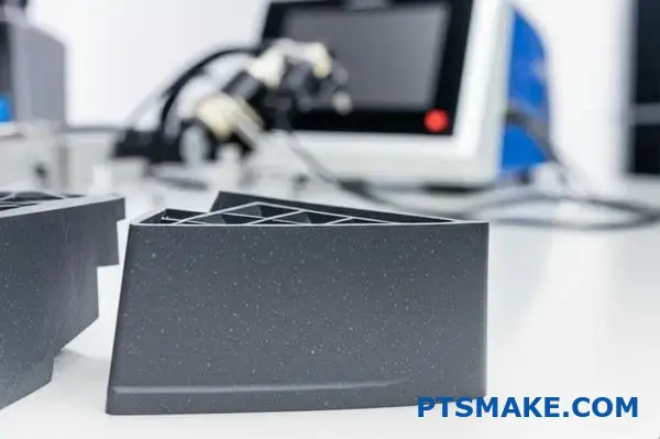
What are the different methods for plastic part holding and alignment?
Proper fixturing is the foundation of repeatable manufacturing. A nest or jig holds your plastic part securely. It ensures perfect alignment for every cycle.
This is especially true for assembly processes. Think of operations like ultrasonic plastic welding. The right fixture makes all the difference.
Fixture Material Choices
Choosing the right material is your first step. Each has unique benefits for different applications. We often guide clients based on their project’s specific needs.
| Material | Key Advantage | Best For |
|---|---|---|
| Steel | Maximum rigidity & life | High-volume, abrasive materials |
| Aluminum | Good rigidity, machinable | Most general applications, prototypes |
| Poured Urethane | Conforms to part shape | Complex, delicate, or cosmetic parts |
Essential Design Elements
A fixture must do more than just hold the part. It needs to support it correctly and align it precisely. Alignment pins and contoured surfaces are critical features.
A rigid fixture is non-negotiable for good welds. This is a core principle we follow at PTSMAKE. When a fixture flexes, it absorbs the energy intended for the weld joint. This leads to weak or incomplete bonds.
For a process like ultrasonic plastic welding, all the high-frequency energy must be directed into the plastic. A solid, unyielding fixture acts as a perfect anvil. It reflects the energy back into the weld interface, creating the necessary friction and heat for a strong melt.
Energy Management in Fixturing
The fixture’s design directly impacts energy transfer. It must support the part directly under the weld area. This ensures the vibratory energy is not lost. Poor support leads to inconsistent results.
Based on our testing, a fixture with poor Acoustic Impedance8 matching can reduce weld strength by over 50%. It’s a critical factor in process control.
| Feature | Purpose | Impact on Quality |
|---|---|---|
| Part Support | Prevents part flexing under pressure | Ensures consistent energy transfer to the joint |
| Alignment Pins | Precisely locates parts relative to each other | Guarantees accurate assembly and weld location |
| Clamps | Secures the part firmly in the nest | Stops movement during the welding cycle |
We design fixtures that not only hold the part but also optimize the physics of the assembly process.
The choice of fixture material and design is crucial. Rigidity is paramount, especially for energy-based processes like ultrasonic plastic welding. A well-designed fixture ensures consistent, high-quality results by properly supporting the part and directing energy to the weld joint.
How do you systematically develop a new welding process from scratch?
Developing a new welding process requires a clear, step-by-step plan. Guesswork leads to wasted time and resources. The foundation of success is a systematic methodology.
This structured approach ensures that every variable is considered. It moves from broad requirements to fine-tuned parameters.
Defining Clear Requirements
First, we must define what "success" looks like. We work with clients to establish clear, measurable goals for the weld. This is the most critical phase.
Key Performance Indicators
- Strength: What load must the weld bear?
- Cosmetics: Are there specific visual standards?
- Cycle Time: How fast does the process need to be?
Here is a simple breakdown of common requirements.
| Requirement Type | Example Metric | Importance |
|---|---|---|
| Mechanical | Tensile Strength > 50 MPa | High |
| Aesthetic | No flash or discoloration | Medium |
| Production | Cycle time < 10 seconds | High |
This clarity guides all subsequent decisions in the process development.
The Path from Concept to Production
Once requirements are set, we move to the technical details. This is where engineering expertise comes into play, especially for complex applications. We break it down into logical phases.
Joint Design and Material Considerations
The joint design is fundamental. It must be suitable for the chosen welding method and materials. For example, the design for ultrasonic plastic welding is very different from other methods.
Material selection also dictates our starting point. We analyze the polymer’s properties, such as melt flow index and glass transition temperature. These factors heavily influence initial parameter selection.
Parameter Selection and Optimization
We begin with a baseline set of parameters. These are derived from material datasheets and past project experience at PTSMAKE. This is just the starting point.
The real magic happens during iterative optimization. We use a Design of Experiments (DOE) approach to efficiently test variables. This method allows us to see how factors like pressure, temperature, and time interact.
Using a structured method like an orthogonal array9 helps us test multiple variables simultaneously. It dramatically reduces the number of trials needed. This saves both time and material.
| Factor | Level 1 | Level 2 | Level 3 |
|---|---|---|---|
| Weld Pressure | 0.3 MPa | 0.4 MPa | 0.5 MPa |
| Weld Time | 0.5 sec | 1.0 sec | 1.5 sec |
| Amplitude | 60 microns | 70 microns | 80 microns |
This systematic process fine-tunes the operation. We continue until all initial requirements are consistently met, ensuring a robust and repeatable welding process.
A systematic approach transforms process development from an art into a science. By defining requirements, designing the joint, setting initial parameters, and using DOE for optimization, we create a reliable and efficient process. This ensures consistent quality from the first part to the last.
How do you diagnose weld quality using cross-sectioning and microscopy?
Diagnosing weld quality is a precise, methodical process. It is not about guesswork. It provides a clear window into the internal structure of a joint.
This guide breaks it down into three core steps. Following them ensures you get accurate, repeatable results every time. It’s a fundamental skill for quality assurance.
The Essential Workflow
The procedure can be simplified into three main stages. Each stage builds upon the last, leading to a conclusive analysis.
| Step | Objective | Key Equipment Needed |
|---|---|---|
| 1. Cutting | Isolate a clean cross-section | Low-speed diamond saw |
| 2. Polishing | Create a mirror-smooth surface | Polishing machine, abrasives |
| 3. Examination | Identify and document defects | Metallurgical microscope |
A Practical Guide to Weld Analysis
Let’s explore each stage in more detail. In our past projects at PTSMAKE, we’ve found that skipping or rushing any of these steps leads to unreliable data. Precision at every stage is non-negotiable.
Step 1: Cutting the Sample
First, you must cut the sample perpendicular to the weld line. We use a low-speed precision saw with a diamond-coated blade.
This technique is crucial. It minimizes heat and mechanical stress on the sample. A rough cut can introduce damage that might be mistaken for a weld defect later.
Step 2: Polishing the Cross-Section
After cutting, the sample is typically mounted in an epoxy resin. This makes it easier to handle during polishing.
The polishing process begins with coarse-grit abrasive papers. We then move to progressively finer grits. The goal is to remove all scratches from the cutting stage.
Finally, we use a fine polishing suspension. This creates a mirror-like, scratch-free surface. This level of clarity is essential for accurate microscopic viewing. The analysis of interfacial bonding10 depends entirely on this preparation.
Step 3: Microscopic Examination
With a perfectly polished sample, we move to the microscope. Here, we can finally see the weld’s internal story. This is especially critical for processes like ultrasonic plastic welding.
Common Weld Defects to Identify
| Defect Type | Visual Characteristics | Common Causes |
|---|---|---|
| Voids | Small, often spherical, pockets within the weld | Trapped air, moisture, or outgassing |
| Poor Bonding | A clear line of separation at the weld interface | Insufficient energy, pressure, or time |
| Degradation | Charred, burnt, or discolored material | Excessive energy or weld duration |
| Insufficient Flow | The weld material fails to fill the joint completely | Incorrect parameters or joint design |
This three-step process—precise cutting, methodical polishing, and detailed microscopic examination—is the gold standard. It transforms quality assessment from an assumption into a science, providing clear evidence of a weld’s structural integrity.
What is a systematic approach to troubleshooting inconsistent weld strength?
A logical flowchart is the best tool for troubleshooting. Don’t jump to complex settings. Start with the basics first. This methodical process saves time and frustration.
We always begin with the most common variables. These often cause the biggest problems. Check these before touching any machine parameters.
Initial Physical Checks
First, confirm the physical setup is sound. Inconsistent parts or a loose fixture can ruin any weld.
| Variable to Check | Key Inspection Point |
|---|---|
| Part Consistency | Are dimensions, material, and gate locations identical? |
| Fixture Stability | Is the part held securely with no movement? |
| Stack Tightness | Are all components (horn, booster, converter) tight? |
| Pressure Regulation | Is the air pressure consistent and correctly set? |
These simple checks solve many issues.
Developing a Deeper Troubleshooting Logic
A systematic approach prevents random guessing. It forces you to rule out simple causes before tackling complex ones. This is crucial in high-precision manufacturing.
At PTSMAKE, we treat troubleshooting like a science experiment. We change one variable at a time. This helps us isolate the root cause effectively. Otherwise, you never truly know what fixed the problem.
Escalation Path for Weld Issues
If initial checks pass, you can move on. Now, we look at machine parameters and material properties. This is a more advanced step.
Some polymers are hygroscopic11, meaning they absorb moisture. Based on our test results, this can drastically affect weld strength. So, material condition is a critical checkpoint.
The table below shows a logical escalation path for ultrasonic plastic welding.
| Stage | Focus Area | Example Actions |
|---|---|---|
| Stage 1 | Mechanical Setup | Verify part fit, fixture security, and stack tightness. |
| Stage 2 | Process Parameters | Adjust weld time, hold time, or amplitude incrementally. |
| Stage 3 | Material Integrity | Check for moisture content, contamination, or batch variation. |
| Stage 4 | Equipment Health | Inspect the horn and converter for wear or damage. |
This structured method ensures nothing is overlooked.
A systematic flowchart saves time by addressing common physical issues first. By confirming part consistency, fixture stability, and pressure before adjusting parameters, you can isolate problems much more efficiently and avoid unnecessary complications.
How would you troubleshoot a high reject rate for cosmetic defects?
Solving high cosmetic defect rates requires a broad view. It’s rarely a single issue. The problem often connects design, tooling, and process. Each area can create or worsen flaws.
Holistic Problem-Solving
You must analyze the entire system. A small design flaw can be amplified by incorrect process settings. We see this often in manufacturing.
Key Areas of Investigation
A systematic check is necessary. We start by isolating variables. This helps pinpoint the root cause without confusion.
| Domain | Common Root Cause |
|---|---|
| Part Design | Sharp internal corners |
| Tooling | Uneven horn contact |
| Fixtures | Inadequate part support |
| Process | Excessive force or time |
A Deeper Dive into Root Causes
A high reject rate is a puzzle with many pieces. In past projects at PTSMAKE, we’ve learned that these pieces are interconnected. You cannot troubleshoot one area in isolation.
The Domino Effect in Manufacturing
Consider a part with sharp internal corners. This design choice creates a point of high stress concentration12. This weakness may not be a problem on its own.
However, combine it with a fixture that provides poor support. The part can now flex during processing. This adds even more strain.
Now, apply excessive force during an assembly process like ultrasonic plastic welding. The high force, combined with the stress from the sharp corner and poor support, causes a crack or a burn mark. The defect appears.
Interconnected Parameters
Each parameter influences the others. Adjusting one without considering the impact on the rest is a common mistake. It can lead to chasing problems around without finding a real solution.
| Factor | Interaction with Other Factors | Potential Defect |
|---|---|---|
| Part Design | Influences tooling and fixture requirements | Cracks, sink marks |
| Tooling | Affected by part geometry and process settings | Flashing, uneven welds |
| Fixtures | Critical for managing process forces | Part deformation, scuffs |
| Process | Must be tuned to design and tooling | Burn marks, material degradation |
We found that mapping these interactions is the fastest way to a stable and reliable manufacturing process.
A systematic approach is essential for cosmetic defects. You must analyze how part design, tooling, fixtures, and process parameters interact. This integrated view reveals the true root cause, preventing a cycle of temporary fixes and recurring problems.
How do you manage welding projects involving very thin or delicate parts?
Handling very thin or delicate components is a common challenge. Success depends on using advanced techniques with precision. It’s about finesse, not force.
We focus on minimizing stress on the parts. This ensures a strong weld without causing damage or distortion.
Key Advanced Techniques
Fine-Tuning The Process
We start by adjusting the core parameters. This includes using a lower amplitude to reduce vibrational stress. It’s a critical first step.
Here are some core strategies we use at PTSMAKE.
| Strategy | Primary Goal | Best For |
|---|---|---|
| Low Amplitude | Reduce stress on the part | Extremely thin or brittle materials |
| Collapse Distance Control | Ensure consistent weld depth | Applications requiring high precision |
| Specialized Fixtures | Prevent part movement/distortion | Complex or asymmetrical geometries |
| Intermediary Film | Absorb and distribute energy | Heat-sensitive or clear plastics |
These methods allow for much greater control.
Integrating Advanced Control for Success
For challenging applications, we must combine several advanced strategies. It’s not about a single solution, but a complete system approach.
Low Amplitude and Precise Control
Using low amplitude13 is fundamental. It reduces the mechanical stress on delicate parts during the weld cycle. This prevents cracking or material fatigue.
We pair this with extremely precise collapse distance control. Instead of welding by time, we weld to a specific depth. This ensures every weld is identical and prevents over-welding. This is vital for medical devices or electronics.
The Role of Support and Energy Management
Specialized fixtures are non-negotiable. The fixture must fully support the part, leaving no area unsupported. This prevents any flexing or vibration that could lead to failure.
In some ultrasonic plastic welding projects, we’ve introduced an intermediary energy-absorbing film. This thin film is placed between the horn and the part. It helps distribute the ultrasonic energy more evenly.
This technique is particularly useful for preventing surface marking on cosmetically sensitive parts.
| Challenge | Advanced Solution | Key Benefit |
|---|---|---|
| Part Cracking | Use low amplitude settings | Minimizes mechanical stress and heat buildup |
| Inconsistent Welds | Implement precise collapse distance control | Achieves repeatable results with tight tolerances |
| Part Distortion | Design fully supportive fixtures | Eliminates movement and ensures proper alignment |
| Surface Marking | Apply an intermediary energy film | Diffuses energy to protect the part’s surface |
By combining these methods, we can successfully weld even the most fragile components.
Managing delicate welding projects requires more than standard procedures. It involves integrating low amplitude, precise collapse control, custom fixtures, and sometimes energy films. This multi-faceted approach ensures both strength and integrity for the most challenging parts.
How do you create a process control plan for a critical medical device?
For critical medical devices, there is no room for error. A robust process control plan is not just good practice; it’s a requirement. This plan is your playbook for consistency and safety.
The Foundation: 100% Data Monitoring
Every single part matters. That’s why we monitor 100% of welds. We capture data for every cycle to ensure nothing is missed. This provides complete traceability.
Key Weld Parameters
We focus on the critical-to-quality (CTQ) parameters.
| Parameter | Why It’s Monitored |
|---|---|
| Weld Power | Ensures sufficient energy for a strong bond. |
| Collapse Distance | Confirms material flow and joint integrity. |
| Weld Time | Controls the duration of energy application. |
| Frequency | Verifies welder performance and stability. |
This real-time data is the core of our control strategy.
Creating the control plan is a methodical process. It moves from process understanding to active control and response. It’s about defining the rules before the game starts.
Setting Control Limits
First, you must establish Upper and Lower Control Limits (UCL/LCL). These are not random guesses. They are determined statistically during process validation, often using a Design of Experiments (DOE).
These limits create a "safe window" for production. For any given parameter, like power in an ultrasonic plastic welding process, the machine’s output must fall within this window.
Defining Actions for Deviations
What happens when a weld is out-of-spec? Your plan must define this clearly. There is no ambiguity. In our past projects at PTSMAKE, we have established a clear protocol for this.
Immediate Actions
Any part produced from an out-of-spec weld is immediately segregated. It is quarantined to prevent it from ever reaching the next stage. This is a non-negotiable first step.
The system should also trigger an alarm to alert operators and engineers.
Investigation and Correction
Next, an investigation begins. We analyze the data to understand the root cause. This could be material variation, equipment drift, or an operator error. The formal process for this is a core part of Corrective and Preventive Actions (CAPA)14. Based on our findings, we take action to bring the process back into control.
A successful control plan for a critical medical device hinges on three things: 100% data monitoring, statistically defined control limits, and a clear, immediate action plan for any out-of-spec results. This ensures part quality and patient safety.
When should you choose ultrasonic welding over other joining methods?
Choosing the right joining method is a critical decision. It impacts production speed, cost, and the final quality of your product. This isn’t just about picking a technology. It’s about a strategic choice.
Making the Right Call
Ultrasonic welding is fantastic for its speed and precision. But it is not always the best fit for every project. Other methods like vibration or laser welding have their own strengths.
Let’s look at a simple comparison.
| Method | Best For | Key Consideration |
|---|---|---|
| Ultrasonic | High volume, small parts | Material compatibility |
| Adhesive | Dissimilar materials | Cure time, surface prep |
This table gives a quick overview. A deeper dive is needed to make an informed choice.
Making the best choice requires a clear framework. At PTSMAKE, we guide clients using a comparison matrix. This helps visualize the trade-offs between different assembly methods. It clarifies the best path forward.
The Comparison Matrix
This matrix evaluates key factors for each joining method. It’s a tool we’ve refined through many projects to help our partners make strategic decisions. The process starts by understanding how different methods generate heat. For instance, ultrasonic and vibration methods both rely on generated frictional heat15 to melt and fuse the plastic.
Detailed Evaluation
Here is a breakdown of how ultrasonic plastic welding compares to common alternatives. This data comes from our internal testing and project experience.
| Factor | Ultrasonic Welding | Vibration Welding | Laser Welding | Adhesives/Solvents |
|---|---|---|---|---|
| Cycle Time | Very Fast (1-2 sec) | Moderate (15-30 sec) | Fast (5-15 sec) | Slow (minutes to hours) |
| Material Comp. | Good (esp. rigid) | Excellent (wide range) | Good (transmissive/absorptive) | Excellent (dissimilar) |
| Tooling Cost | Moderate | High | High | Low |
| Joint Geometry | Needs specific design | More flexible | Very flexible | Highly flexible |
| Hermetic Seal | Excellent | Good | Excellent | Variable |
Key Takeaways
Ultrasonic welding shines with its incredibly fast cycle times. This makes it ideal for high-volume production. However, tooling can be a significant initial investment compared to using adhesives.
The best joining method depends on your project’s specific needs. Ultrasonic welding is a top choice for speed and creating strong, hermetic seals on compatible plastics. This matrix provides a clear starting point for your decision-making process.
How would you solve a welding problem caused by inconsistent parts?
Welding issues often point to the process itself. But the true problem might be external. Inconsistent parts are a frequent, yet overlooked, cause.
The Real Culprit
When parts don’t match specifications, your welding process suffers. Trying to adjust welder settings for every bad part is not a solution. It’s a temporary fix that creates more problems.
First, Quantify the Problem
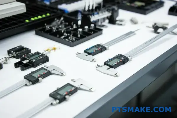
Before touching the welder, measure the parts. Use precise tools to understand the variation. This data is your starting point for a real solution.
| Approach | Description | Outcome |
|---|---|---|
| Reactive | Adjusting welder for each part | Inconsistent welds, high scrap |
| Proactive | Measuring parts, fixing the source | Consistent quality, lower costs |
A Data-Driven Approach to Consistency
Chasing welding parameters for inconsistent parts is inefficient. The better strategy is to fix the parts first. This ensures a stable foundation for the entire assembly process, especially for something as precise as ultrasonic plastic welding.
Quantifying Variability
The first step is always to gather data. We must understand the extent of the inconsistency. This isn’t about blaming a department or a supplier. It’s about objectively defining the problem. We use measurement tools to quantify the part-to-part variability16. This tells us exactly how much the dimensions differ from the nominal design.
| Measurement Tool | Best For | Precision Level |
|---|---|---|
| Digital Calipers | Quick checks, basic dimensions | Good |
| Micrometers | Critical thickness, diameters | High |
| CMM | Complex geometries, full analysis | Very High |
Collaborating with the Source
With clear data, you can work with the source. This might be your internal molding department or an external supplier. In our projects at PTSMAKE, we foster direct communication. We share the CMM reports and work together to find the root cause in the molding process. This collaborative approach solves the problem permanently. It prevents future issues and improves the overall product quality.
A stable welding process starts with consistent parts. The best strategy is to measure part variability first. Then, collaborate with the molding department or supplier to address the root cause, rather than constantly adjusting the welder.
How can you leverage automation with ultrasonic welding for high-volume production?
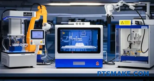
Thinking beyond a single machine is key. The future of high-volume production lies in system-level integration. We must see ultrasonic welding not as an isolated step, but as a connected part of a larger, intelligent manufacturing ecosystem.
The Next Frontier: System-Level Integration
This approach combines multiple advanced technologies. It creates a seamless flow from raw parts to finished goods. Each component communicates to optimize the entire line.
Smarter, Faster, Better
We can integrate robotics for precise part handling. Vision systems can perform inspections before the weld even happens. Automated data collection feeds directly into your factory’s Quality Management System (QMS).
| Feature | Traditional Automation | Integrated System |
|---|---|---|
| Part Handling | Manual or simple feeders | Robotic arms |
| Inspection | Post-production checks | Real-time vision systems |
| Data | Manual logging | Automated QMS feed |
| Optimization | Reactive adjustments | Predictive analytics |
Integrating these systems transforms the production floor. It moves us from a reactive to a proactive manufacturing model, which is essential for scaling up production efficiently and reliably. At PTSMAKE, we guide our clients through this evolution.
Creating a Smart Welding Ecosystem
This is about building a cohesive, self-monitoring process. Robotics do more than just move parts. They ensure perfect orientation and placement every single time, which is critical for consistent weld quality in any ultrasonic plastic welding application.
The Role of Advanced Vision Systems
Modern vision systems are incredibly powerful. They can inspect parts for molding defects, contamination, or incorrect assembly before they reach the welder. This simple pre-weld check prevents the creation of a bad part, saving significant material and time.
Data: The Backbone of Quality
Every single weld generates valuable data. We’re talking pressure, amplitude, and energy consumed. In an integrated system, this data is automatically captured. This information builds a digital twin17 of the production process. It allows for real-time monitoring and historical analysis, forming the core of a robust QMS.
| Integrated Technology | Primary Benefit | Impact on Production |
|---|---|---|
| Robotics | Consistency & Speed | Reduced cycle times, fewer handling errors |
| Vision Systems | Proactive Quality Control | Lower scrap rates, improved part quality |
| Automated Data | Process Transparency | Enhanced traceability, predictive maintenance |
The future of high-volume ultrasonic welding is an interconnected system. By integrating robotics, vision, and automated data collection, we create a smart ecosystem that boosts efficiency, prevents defects, and provides unparalleled process control.
Take the Lead in Ultrasonic Plastic Welding with PTSMAKE
Ready to elevate your production with advanced ultrasonic plastic welding solutions? Contact PTSMAKE today for a personalized quote or technical consultation. Discover why leading manufacturers worldwide trust us for precision, quality, and consistency from prototype to large-scale production. Send your inquiry now!

Learn how this key property impacts material selection and joint design for optimal strength. ↩
Learn more about the core principle of how ultrasonic waves generate heat in polymers. ↩
Understand how this material property enables strong, hermetic seals in ultrasonic welding. ↩
See how polymers break down during welding and learn specific methods to prevent this issue. ↩
Discover the science behind converting electrical signals into the mechanical motion essential for ultrasonic welding. ↩
Learn what amplitude means in ultrasonic welding and why it’s a critical parameter for success. ↩
Learn how this core material property dictates the success of your welding process. ↩
Learn how this property affects energy transfer and weld quality in ultrasonic applications. ↩
Discover how this statistical tool simplifies complex testing and accelerates process optimization. ↩
Learn more about how molecular forces create strong, reliable weld joints. ↩
Learn how moisture absorption can dramatically affect polymer welding performance and integrity. ↩
Learn how this concept creates weak points that lead to cracks and other cosmetic flaws. ↩
Learn more about how vibrational amplitude affects weld quality and material integrity. ↩
Understand how CAPA systems drive quality improvement and ensure full regulatory compliance. ↩
Understand the science behind how vibration generates heat to create a molecular bond in plastics. ↩
Learn how this key quality metric impacts welding and overall manufacturing efficiency. ↩
Learn how this virtual model can revolutionize your manufacturing process by predicting outcomes and optimizing performance. ↩