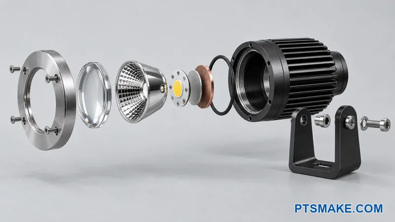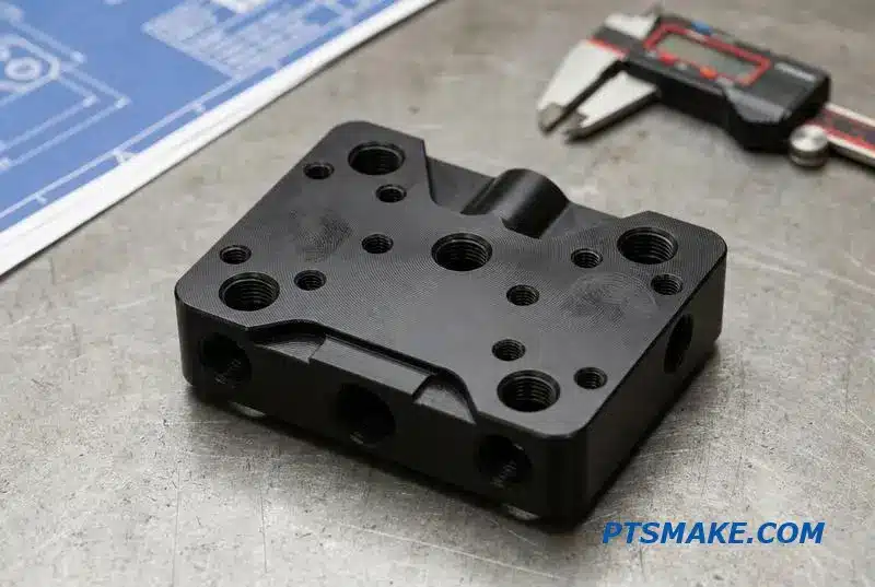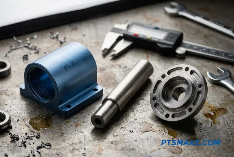

An amplifier chassis can look finished in CAD while hidden access, datum, heat, grounding, and finish conflicts still make the part unstable or costly to build.
Quick answer: A manufacturable aluminum amplifier chassis starts with a suitable part split, controlled component interfaces, rigid cutter access, and finish-aware thermal and grounding surfaces. The design should assign tight tolerances only where assembly, heat transfer, alignment, or compliance work requires them.
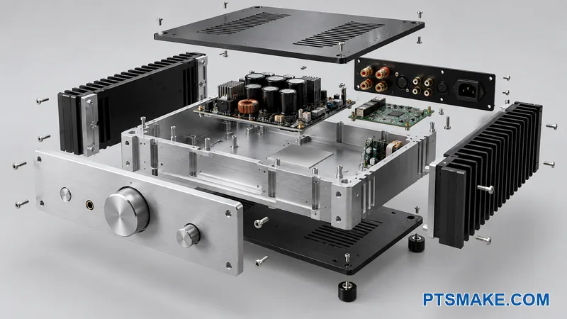
I review the chassis as an assembly system before I review isolated dimensions. The sequence below keeps product decisions with the responsible engineers while exposing the choices that affect machining, finishing, inspection, and quotation.
Send the current CAD and interface files for an early chassis DFM review.
Choose the Right Aluminum Amplifier Chassis Architecture
Define the manufacturing brief first
A useful DFM review starts with confirmed product inputs. The CAD model alone does not show allowable component temperatures, electrical clearances, cosmetic priorities, service needs, load cases, or required product tests. It also does not show which component models are released and which ones are still placeholders.
The design team should provide the PCB outlines and mounting pattern. The package should also identify transformers, power devices, displays, switches, knobs, rear connectors, cable envelopes, internal shields, thermal interface materials, and removable panels. Each purchased item needs a supplier part number and a controlled drawing or 3D model. A photograph or marketing illustration cannot define a final cutout.
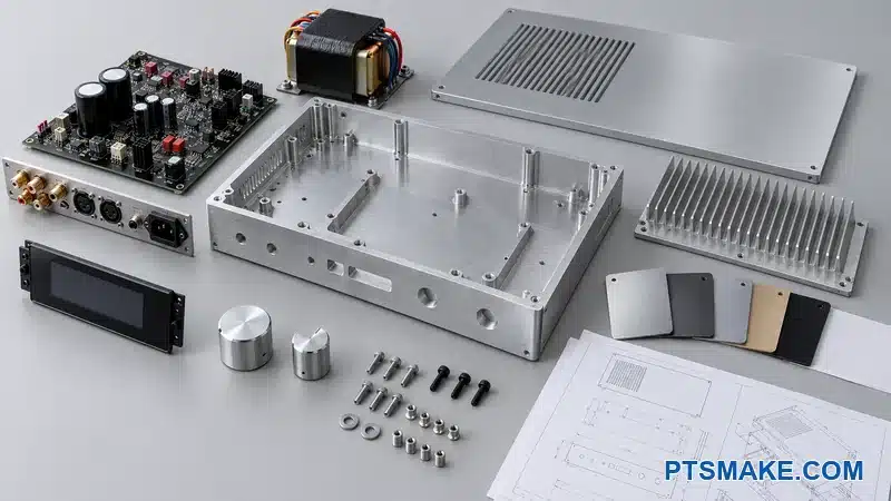
Separate fixed, preferred, and open inputs
I assign every important input one of three states. A fixed input controls function, safety, regulatory work, or compatibility. A preferred input may change after a tradeoff review. An open input gives the manufacturing team room to improve access, stock use, or assembly.
| Input state | Typical amplifier chassis example | DFM response |
|---|---|---|
| Fixed | Released connector body, PCB hole pattern, thermal limit, or external rack interface | Protect the interface and define how it will be verified |
| Preferred | Joint location, edge treatment, fastener style, or internal pocket shape | Compare manufacturing risk, appearance, and service impact |
| Open | Hidden relief, tool entry, local rib shape, or fixture land | Let the process owner propose a practical form |
The same brief should state prototype and expected production quantities. It should identify visible surfaces, product-level validation owners, revision status, and unresolved decisions. This record prevents a temporary assumption from becoming an expensive permanent feature.
Compare the part-split options
A one-piece milled body can reduce seams and create a strong visual form. However, it may start from a large block, remove substantial material, restrict tool access, and require several orientations. A multi-panel chassis uses simpler pieces and can improve service access, but it adds joints, hardware, alignment features, and finish-matching work.
An extrusion can carry a repeated cross-section, including rails or heat-sink fins. Secondary CNC work then creates the panel and connector features. This route becomes more attractive when the same cross-section supports stable demand, but profile tooling, order quantity, straightness, end access, and later revisions still need review. A hybrid design can combine a machined thermal base with removable sheet or machined panels.

The best architecture is the one that satisfies the actual interfaces with acceptable manufacturing and lifecycle risk. I check how the electronics enter the chassis, how each fastener is reached, how cables bend, and how a serviced board leaves the assembly. A closed cavity that looks clean from the outside can make installation or repair impossible.
Match Alloy, Stock Form, and Finish
Specify alloy, temper, and product form
An aluminum name without a temper and product form is incomplete. The aluminum alloy designation system1 distinguishes compositions and tempers because processing changes properties. The drawing and purchase package should identify the required alloy, temper, product form, and certification need. The supplier should not infer those items from color or a previous revision.
6061 is a common candidate, but the design team should still check the specific product data. For example, Hydro lists mechanical limits and a typical thermal conductivity for 6061-T6 and T6511 extrusion2. Those values describe the stated product and temper. They do not prove the complete chassis temperature or justify using the same number for every plate, extrusion, or finished part.
Thick plate for a deep body also needs a material-condition review. A producer describes low-residual-stress aluminum plate3 as a way to support flatness and reduce movement during machining. The design still needs geometry-specific allowance for stock removal, clamping, stress release, and finish.
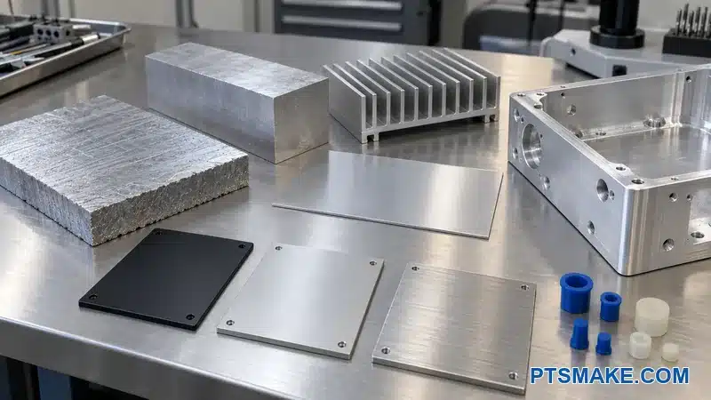
Match stock form to the architecture
Plate or billet supports a monolithic body and flexible pocket geometry. It can also create a poor purchased-to-finished mass ratio. Extrusion can place material near repeated walls, rails, or fins, but it constrains the cross-section and may still need substantial secondary machining. Sheet or thinner plate works well for removable covers and simple panels when stiffness, joining, appearance, and grounding joints remain acceptable.
I compare the purchased stock envelope with the final part before detailed pocketing begins. Standard stock availability can matter more than a small change in finished size. The review should also consider saw allowance, workholding material, fixture contact, and the surfaces that need clean-up after stock variation.
Treat finishing as a geometry input
The finish plan affects dimensions, electrical contact, thermal contact, color matching, and handling. The team should identify masked bores, threaded features, grounding lands, thermal interfaces, rack points, and permitted contact marks before the final machining dimensions are released. The later aluminum anodizing process cannot correct an alloy or geometry that was chosen without finish input.
Build Datums Around Component Interfaces
Create one mechanical interface map
The chassis connects several independent component chains. A PCB boss controls board height. That height affects a switch shaft, display reveal, rear connector, cable bend, and lid clearance. A thermal land controls the power-device interface, while the feet or rack ears control how the assembled product sits in its final installation.

An interface table makes these relationships visible before tolerances are assigned.
| Interface | Controlling chassis features | Information required | Verification example |
|---|---|---|---|
| PCB to front controls | Boss tops, locating holes, front-panel face, control bores | Released PCB and control models, panel stack, desired reveal | Assembly fixture or defined dimensional chain |
| PCB to rear connectors | Boss pattern, rear datum face, connector cutouts | Supplier connector drawing, insertion direction, nut and cable access | Connector fit and critical position checks |
| Power device to chassis | Device seat, thermal land, fastener pattern | Heat load, interface material, clamping method, allowable temperature | Surface and assembled thermal validation |
| Lid to base | Mating ledge, locating features, screw pattern | Gap intent, finish, service sequence, grounding or sealing need | Fit, gap, continuity, or sealing test as applicable |
| Chassis to product | Feet, rack ears, external mounting points | Load, installation envelope, external references | Assembly fit and product-level load check |
Select datums from function
A large flat surface is not automatically the right primary datum. The primary reference should constrain the most important degrees of freedom and remain practical to machine and inspect. A secondary plane should orient the component chain, and a tertiary reference should complete location without creating an unstable or ambiguous setup.
The ASME Y14.5 dimensioning and tolerancing standard4 provides the common language for datums and geometric controls. The drawing still needs a product-specific scheme. A symbol does not replace the reasoning that connects a tolerance to fit, function, and verification.
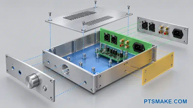
I often start with the PCB or thermal mounting plane when it controls several functional relationships. A rear connector face may become the secondary datum when connector projection and panel alignment matter. A side or locating feature can complete the reference frame. Another chassis may need a different order because its rack ears, front cosmetic face, or external mounting points carry the main functional risk.
Allocate tolerances backward from assembly
The team should calculate the allowable assembly error first. It can then allocate that error across the component, PCB, chassis, panel, and fastener interfaces. This method avoids placing one very tight position tolerance on the chassis while ignoring a larger variation in a purchased component.
Consider a clearly hypothetical display example. Suppose the acceptable visible offset is defined by the design team. The stack includes the display module, its PCB location, the boss pattern, the front-panel locating features, and the window. The designer should allocate the available offset across all five contributors and include assembly clearance. A tight window tolerance alone cannot control the final reveal.
The same logic applies to knob shafts and rear connectors. A large connector nut may tolerate a generous cutout, while a close decorative reveal may need a controlled relationship to the front face. The drawing should distinguish those needs.
At PTSMAKE, tolerances as tight as ±0.005 mm may be achievable, depending on the material, geometry, feature size, setup, process, drawing review, and inspection method. That conditional capability is not a general chassis tolerance. The tight-tolerance CNC machining guide provides more context, but each amplifier chassis still needs an individual capability review.
Make the Chassis Reachable and Stable in Machining
Start with the stock envelope and setup plan
Material removal is only one cost driver. The manufacturing route also includes saw preparation, workholding, reorientation, datum transfer, deburring, cleaning, finishing, and inspection. A large chassis may occupy the machine long before the cutter reaches the features that define function.
I sketch a setup plan while the architecture is still open. The plan identifies the first gripping surfaces, the faces exposed in each orientation, the functional references reused later, and the areas reserved for clamps or soft jaws. It also shows whether the final thin walls remain supported while the critical features are cut.
At PTSMAKE, we use 3-axis, 4-axis, and 5-axis CNC milling for different geometries. More axes can improve access or reduce re-clamping, but they do not make every integrated shape economical. A separate panel can still be the better answer when it opens a deep cavity, protects a cosmetic face, or simplifies assembly. The available CNC machining services should support the design rather than drive it without a functional reason.
Open deep cavities to the complete tool assembly
A CAD clearance check often uses only the cutting diameter. The real envelope includes the flute length, neck, shank, holder, spindle nose, approach angle, and chip path. The cutter must reach the floor without the holder rubbing a wall or the long tool bending under load.
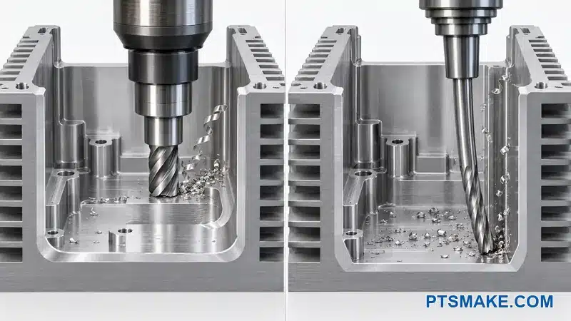
Tool suppliers advise using the shortest possible tool overhang5 to improve stability. This principle makes cavity opening, wall height, corner radius, and floor steps important DFM variables. Geometric reach alone does not prove stable cutting or the required finish.
Give each deep feature a practical entry path
A larger internal corner radius can allow a stiffer cutter. A stepped floor can keep most machining within a shorter reach. A removable panel can expose side features that otherwise require a long tool or another orientation. Local relief can create holder clearance without changing the visible design.
Small radii should remain only where function needs them. A cutter cannot produce a perfectly sharp internal vertical corner. A designer can use a relief, a mating-part chamfer, or a separate insert when a square mating part must enter the cavity.
Chip evacuation also changes with depth. Recut chips can damage the surface and increase heat. Coolant access, air flow, toolpath, pocket opening, and cleaning requirements should be checked together. A narrow deep channel that traps chips may need a wider opening or a different part split.
Control thin walls, floors, and raised features
Thin walls can move under cutting force. Broad floors can release residual stress or bow after unclamping. Tall bosses may vibrate, and small corner radii can concentrate tool load. The same nominal wall thickness can behave differently when its span, height, support, material condition, tolerance, and finish change.
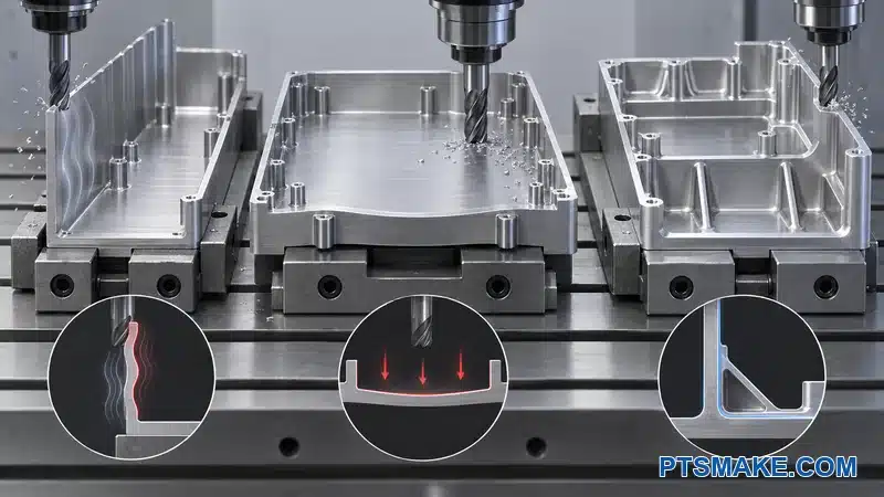
I do not use one universal minimum wall rule for an amplifier enclosure. I check the wall aspect ratio, adjacent mass, cutter access, clamping direction, and the stage at which the wall becomes free. Local thickening can help around connectors or lid screws. Ribs can support a broad panel if the cutter can reach both sides and the transitions do not create new stress or finishing problems.
A clearly hypothetical comparison illustrates the decision. Imagine two chassis bases with the same external envelope and component layout. Version A uses a uniform deep pocket and leaves a broad thin floor. Version B keeps pads under the PCB and thermal interfaces, adds open tool paths between them, and separates a noncritical rear panel. A supplier can compare stock, setups, reach, and distortion risk for both versions. The example does not predict a fixed saving or a universal winner.
Ask for a geometry-specific review before freezing deep cavities or broad thin floors.
Design Fasteners, Lids, and Service Access
Build bosses around load and access
An integral boss needs enough base support, tool clearance, thread depth, and deburring access. A tall narrow boss may save a spacer but add chatter and material removal. A separate standoff can simplify the base, yet it introduces purchased hardware, assembly work, and another interface.
Fastener selection depends on more than nominal diameter. The NASA Fastener Design Manual6 covers material, corrosion, locking, inserts, thread classes, torque, and pullout because these factors interact. An amplifier chassis does not need aerospace hardware by default, but the same systems view prevents a simple screw choice from becoming a weak joint.
The designer should validate engagement against the aluminum condition, screw strength, load, preload, service cycles, thread-forming or cutting method, and finish. Blind holes need room for the drill point, tap lead, chips, and any required bottom clearance. The drawing should identify thread standard and class instead of leaving the shop to infer them. The thread tolerance guide explains the drawing language in more detail.
Plan finish and maintenance together
Anodizing can affect threads and electrical contact. The team should decide whether a thread remains coated, receives masking, or is created after finishing. That choice affects corrosion behavior, dimensions, appearance, cost, and the surrounding surface. Stainless steel hardware against aluminum also needs an environment-specific corrosion review.
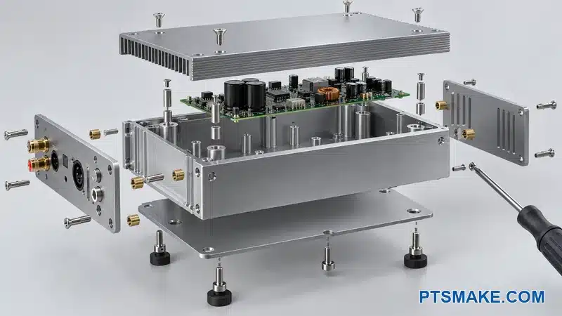
Run the complete removal sequence
The CAD assembly should show the actual driver and hand envelope. A screw that is visible may still be unreachable after the transformer, board, or rear connector is installed. A captive panel may block the next component. A cable may need more bend space than the model allows.
Lids and joints also need locating logic. Screws should clamp the panel, while shoulders, tabs, dowels, or controlled edges can locate it when alignment matters. The team should define acceptable gaps and flushness on visible seams. It should also state which panels are expected to be removed during normal service.
If the product requires ingress protection, the enclosure must be designed and tested against the applicable requirement. IEC 605297 classifies degrees of protection provided by enclosures. A close-fitting CNC joint does not create an IP rating by itself. Gasket geometry, compression, surface condition, fastener loading, cable entries, vents, and assembled-product testing all remain part of the requirement.
Protect Thermal, Grounding, and EMI Interfaces
Define the thermal stack before the machining callout
The electrical or thermal owner should provide device losses, allowable temperatures, airflow conditions, interface material, mounting method, and validation plan. The chassis manufacturer can then evaluate whether the proposed lands, walls, fins, and fasteners are practical to make. The manufacturer should not invent a heat load from amplifier class or marketing power alone.
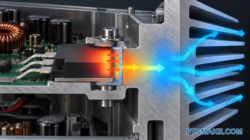
The thermal path can include a power package, electrical isolator, thermal interface material8, machined land, chassis wall, separate spreader, fins, and ambient air. Each interface adds its own contact and assembly conditions. The selected material supplier may specify surface preparation, flatness, pressure, thickness, and cure or dwell requirements. Those product-specific instructions should control the drawing rather than a copied universal flatness value.
The machining review focuses on the surfaces that can be controlled. A thermal land needs an achievable relationship to the device and fasteners. Cutter marks, burrs, raised edges, and finish buildup should not prevent the intended contact. The assembly sequence should create repeatable pressure without bending the board or package.
The drawing should bound the thermal land and distinguish it from nearby cosmetic surfaces. It should also state whether the flatness requirement applies before or after finish. The inspection method needs access to the defined area. If masking creates a raised edge or leaves residue, the assembly can rock even when the central land meets its dimensional callout. The prototype review should include interface compression and the fastener sequence.
Integrated fins can reduce joints, but they may require considerable machining or restrict access. An extruded or separate heat sink can reduce material removal while adding another thermal and fastening interface. The team should compare these routes using the product heat model and test plan. The heat sink design guide can support that analysis, but the chassis article does not claim a temperature result.
Map the conductive enclosure path
Aluminum can contribute to shielding when the assembled conductive path supports the intended electrical design. Electromagnetic shielding9 depends on field behavior, return paths, material, openings, seams, and frequency. A thick machined box with poorly bonded panels or uncontrolled cable entries can still perform badly.
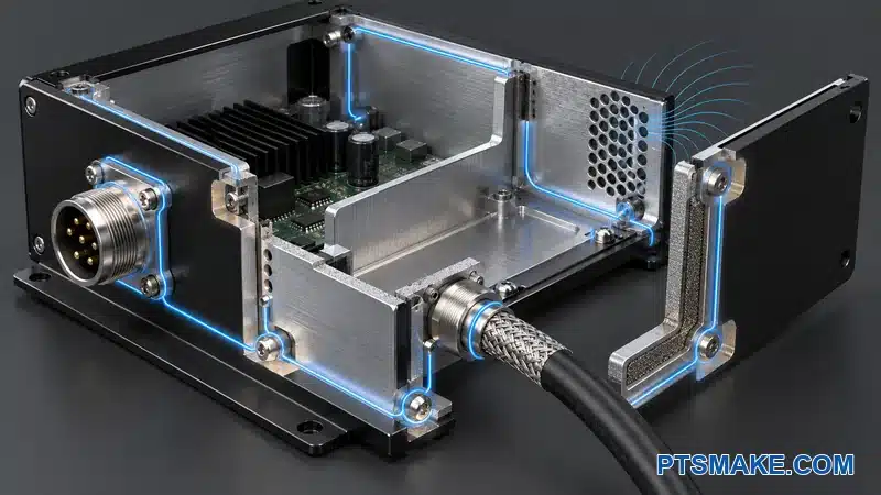
I map intended metal-to-metal contacts across the base, lids, rear panel, connector shells, cable shields, and any conductive gasket lands. The finish drawing should show which regions remain bare and how they are protected or verified. A fastener head may make local contact, but that contact should not become an accidental system strategy.
Keep manufacturing and compliance ownership clear
The chassis drawing can control seam geometry, hole patterns, contact lands, masking, vent geometry, and assembly hardware. The electronics team controls sources, return-current paths, filtering, cable terminations, and layout. The compliance team defines the applicable limits and test configuration.
In the United States, 47 CFR Part 1510 contains requirements for intentional, unintentional, and incidental radiators. The applicable route depends on the complete product and market. CNC machining, anodizing, or a visually closed box cannot guarantee compliance.
The prototype plan should verify continuity where it is required and test the complete product in its representative configuration. Ventilation changes, panel finish, cable routing, alternate hardware, or a revised PCB can trigger another review.
Share the thermal stack and grounding map with the CAD for a coordinated DFM review.
Release the Finish, Inspection, and Quote Package
Convert appearance into controlled requirements
Terms such as premium, smooth, or matching black are not measurable enough for a supplier. The drawing should classify primary visible surfaces, secondary visible surfaces, hidden surfaces, and functional surfaces. It should define texture direction, edge treatment, acceptable witness zones, protected handling areas, and the viewing conditions used for cosmetic acceptance.
Anodizing requirements also need a recognized process callout when a specification applies. MIL-PRF-862511, for example, covers several anodic coating types and classes for non-architectural aluminum applications. A commercial audio product does not need this military specification by default. The correct requirement should come from the product environment, appearance target, wear needs, corrosion plan, and finishing supplier.
Different alloys, tempers, surface preparations, part geometries, and process lots can change appearance. The team should use approved physical samples and define how panels are grouped when close color matching matters. The drawing should also identify rack locations, masking maps, plugged holes, marking artwork, and surfaces that cannot carry contact damage.
Validate the assembly, not only loose dimensions
An inspection plan should connect every critical feature to a failure consequence and a practical method. The plan can include PCB installation, front-control alignment, display reveal, rear-connector fit, lid gaps, driver access, thermal contact, intended grounding continuity, finish appearance, and external mounting fit. Product-level thermal, safety, EMC, and ingress tests remain with the qualified owners.
The first prototype should close assumptions rather than only confirm that metal was cut. The team should record approved deviations and update both the model and drawing. It should also define which changes require revalidation, such as a new PCB revision, connector source, thermal material, anodizing route, lid geometry, or mounting pattern.
Prepare one controlled release package
A quote-ready package should include native or neutral 3D CAD, controlled 2D drawings, and the datum and geometric-control scheme. It should identify critical dimensions, component files, alloy, temper, threads, inserts, finish, masking, and marking artwork. It should also define the assembly sequence, inspection responsibilities, test ownership, quantities, and revision status.
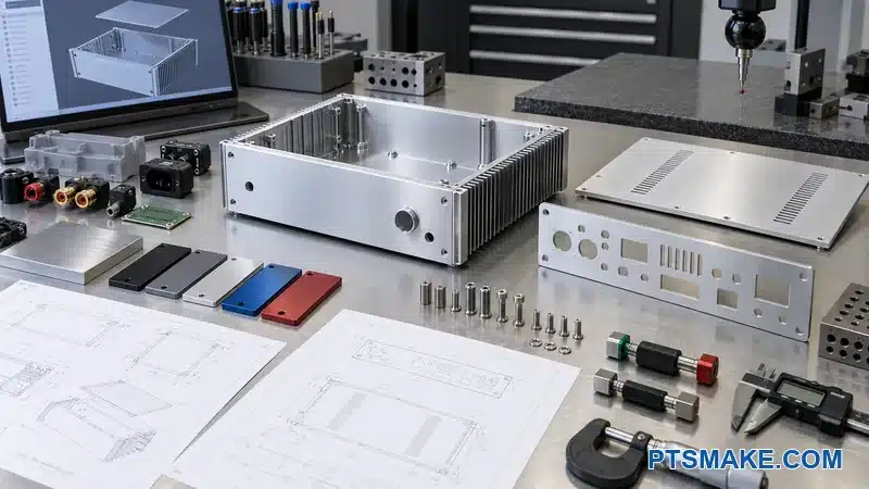
The request should list unresolved questions instead of hiding them. A supplier can then separate assumptions, recurring part cost, tooling or fixture work, finishing, inspection, and lead-time drivers. This structure supports a useful DFM discussion without publishing a universal cost reduction or break-even quantity.
At PTSMAKE, we can machine aluminum using 3-axis, 4-axis, and 5-axis milling. The final route depends on the actual chassis size, features, quantity, material, finish, tolerance, and inspection plan. Complete files allow that review to start from engineering facts rather than guesswork.
Request an Amplifier Chassis DFM Review
Send the CAD model, controlled drawings, component files, quantities, finish requirements, thermal inputs, grounding plan, and unresolved questions. I will use that package to identify machining, assembly, finishing, and inspection risks before the design reaches production.

This system distinguishes registered aluminum compositions and tempers so a material callout communicates more than a generic metal name. ↩
The producer data shows that properties are tied to a stated alloy, temper, product form, and section condition. ↩
Reduced residual stress and controlled plate flatness can help machining stability, but the finished geometry and stock-removal pattern still matter. ↩
The standard supplies consistent rules for datums, geometric controls, and drawing interpretation; the designer must still choose controls from product function. ↩
Shorter tool overhang generally improves rigidity, which is why cavity depth, opening, holder clearance, and corner geometry need a combined review. ↩
Fastener reliability depends on the full joint system, including material, loading, corrosion, locking, thread, torque, and inserts. ↩
The IP Code classifies enclosure protection; a rating applies only after the applicable design and verification requirements are met. ↩
Thermal interface products have their own surface, pressure, thickness, and application requirements, so the selected product data should guide the interface. ↩
Conductive shielding works through controlled field and current behavior; seams, openings, grounding, and source layout affect the assembled result. ↩
The rules apply to the complete regulated device and include technical and administrative requirements that a chassis drawing alone cannot satisfy. ↩
The specification defines multiple anodic coating types and classes, so a drawing must identify the requirement that actually fits the application. ↩