Finding the right ultrasonic welding solution feels impossible when every supplier promises perfect results but fails to deliver consistent quality. You’ve likely experienced the frustration of weld failures, inconsistent bond strength, and production delays that cost your company time and money.
Ultrasonic welding uses high-frequency mechanical vibrations to create frictional heat at material interfaces, enabling strong, permanent bonds without external heat sources. This comprehensive guide covers 18 critical aspects of ultrasonic welding, from basic principles to advanced troubleshooting techniques.
Working with various ultrasonic welding projects at PTSMAKE, I’ve seen how the right knowledge can transform your manufacturing process. This guide will help you master ultrasonic welding fundamentals, avoid common mistakes, and achieve the consistent results your production demands.
What is the first principle of ultrasonic welding energy transfer?
The core principle of ultrasonic welding is simple yet powerful. It transforms electrical energy into mechanical vibration. This high-frequency motion creates intense friction between two plastic parts.
This process generates localized heat right at the joint interface. This is what melts the material. No external heat source is needed. The magic happens entirely within the parts themselves.
How It Works: A Quick Overview
High-frequency vibrations cause the two surfaces to rub against each other. This action generates two types of heat.
| Heat Source Type | Description |
|---|---|
| Surface Friction | Rubbing between the two contact surfaces. |
| Intermolecular Friction | Vibration within the material structure itself. |
This combined friction rapidly increases the temperature. It melts the plastic precisely where the bond needs to form.
The first principle of ultrasonic welding energy transfer is converting high-frequency sound into thermal energy. This happens without any external heaters. The entire process relies on vibration, pressure, and time. It is a highly controlled and efficient method.
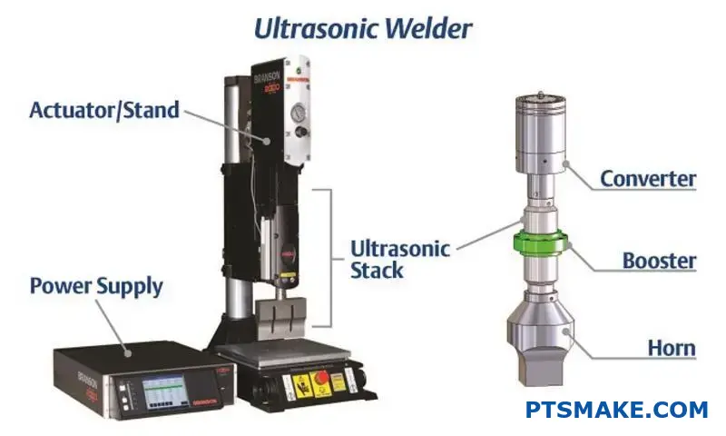
The Energy Conversion Chain
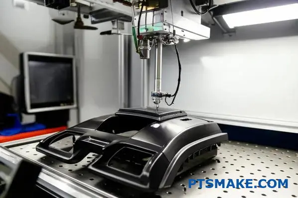
The process begins with a high-frequency electrical signal. This signal powers a transducer. The transducer then converts this electrical energy into mechanical vibrations.
These vibrations travel through a booster and horn assembly. The horn makes direct contact with the part. It transfers this mechanical energy directly to the welding interface.
This is where the energy transforms into heat. It’s caused by two distinct but related phenomena.
Frictional Heat Generation
The most obvious source of heat is surface friction. The parts vibrate against each other thousands of times per second. This rapid rubbing motion generates significant heat right at the joint.
Internal Molecular Heat
A deeper process also occurs. The ultrasonic waves cause the polymer chains within the plastic to vibrate. This internal movement creates intermolecular friction1. It contributes significantly to the rapid temperature rise needed for a weld.
| Energy State | Description |
|---|---|
| Electrical | High-frequency signal from the power supply. |
| Mechanical | Physical vibration of the horn and parts. |
| Thermal | Localized heat from friction, causing melting. |
In our projects at PTSMAKE, understanding this precise energy control is crucial. It allows us to create strong, clean welds for complex components.
The core principle is turning vibration into heat. High-frequency motion creates both surface and intermolecular friction. This generates enough localized heat to melt and fuse plastic parts together quickly and precisely, without external heat sources.
Why is static force (pressure) a critical welding parameter?
Static force is more than just clamping. It’s an active player, especially in processes like ultrasonic welding. Proper pressure is what enables everything else to work.
It ensures the welding horn makes solid contact. This allows energy to transfer efficiently into the parts.
The Role of Pressure in Energy Transfer
Force creates the necessary friction between parts. This initial contact is key for generating heat and starting the melting process where it’s needed most. Without it, energy is lost.
Containing the Molten Material
Once melting begins, the force’s job changes. It contains the molten polymer, preventing it from escaping the joint area. This ensures a solid, uniform bond forms during the hold phase.
| Pressure Level | Coupling Effect | Melt Containment | Weld Quality |
|---|---|---|---|
| Too Low | Poor | Weak | Incomplete |
| Optimal | Excellent | Strong | High |
| Too High | Risk of damage | Excessive flash | Brittle/Damaged |
Ensuring Optimal Contact and Vibration Transmission
The primary function of static force is to establish intimate contact between the welding horn, the top part, and the bottom part. Think of it as creating a clear path for energy.
Without sufficient pressure, microscopic air gaps exist. These gaps disrupt the flow of high-frequency vibrations from the horn. The energy simply reflects back instead of being transmitted to the joint interface. This is a common failure point we’ve identified in past projects.
Proper pressure overcomes surface irregularities. It ensures a consistent medium for the ultrasonic waves to travel through, maximizing the acoustic coupling2 between the components.
From Friction to Fusion
Once vibrations are transmitted effectively, they cause intermolecular friction at the joint interface. This friction generates rapid, localized heat, melting the material precisely where the bond needs to form. The static force then holds this molten material in place.
During the "hold phase" after vibrations stop, the pressure is maintained. This allows the melted plastic to cool and solidify under compression, forming a strong, homogenous bond.
In our work at PTSMAKE, optimizing this pressure is a key step. It directly impacts the final strength and consistency of the weld.
| Parameter | Function During Weld Phase | Function During Hold Phase |
|---|---|---|
| Static Force | Transmits vibration, generates friction | Contains melt, forges molecular bonds |
| Vibration | Creates friction and heat | Inactive |
| Time | Controls energy input | Allows for cooling and solidification |
Static force is fundamental to successful ultrasonic welding. It ensures effective contact for energy transmission and properly contains the molten material during cooling. This controlled pressure is the key to forming a strong, reliable bond between parts.
What defines a material’s ‘weldability’ for ultrasonic processes?
A material’s suitability for ultrasonic welding isn’t random. It’s a science based on specific physical properties. Success depends on how well a material can transmit high-frequency vibrations.
Key Material Properties
Effective energy transmission is crucial. Materials must be rigid enough to carry vibrations to the joint interface without dampening them.
Modulus of Elasticity
A higher modulus of elasticity means better vibration transmission. This allows energy to reach the weld zone efficiently. Softer materials tend to absorb the energy.
| Property | Impact on Weldability |
|---|---|
| High Modulus | Good |
| Low Modulus | Poor |
Melting Temperature
A low melting temperature is generally preferred. It requires less energy to create a molten state at the interface, resulting in a faster weld cycle.

Molecular Structure: The Deciding Factor
The internal structure of a plastic is perhaps the most critical factor. It dictates how the material behaves under ultrasonic energy. Understanding this is key to predicting weldability.
Amorphous vs. Semi-Crystalline
Amorphous plastics have a random molecular structure. They soften gradually over a wide temperature range. This makes them ideal for ultrasonic welding. The energy transfers smoothly through their structure.
In contrast, semi-crystalline3 plastics have ordered, crystalline regions mixed with amorphous areas. These crystalline structures absorb and scatter the ultrasonic energy. They have a sharp melting point, which can make welding more difficult. It requires more energy to break down the crystalline structure.
In projects at PTSMAKE, we often guide clients toward amorphous resins. Or, we design joints specifically to concentrate energy for semi-crystalline materials. This ensures a strong, reliable bond.
| Polymer Type | Weldability | Examples |
|---|---|---|
| Amorphous | Excellent | ABS, PC, Polystyrene |
| Semi-Crystalline | Fair to Good | Nylon, PP, Acetal |
Frictional Characteristics
Materials with a high coefficient of friction generate heat more quickly. This contributes to a faster and more efficient melting process at the joint interface. This initial heat generation is vital for starting the weld.
Material properties like modulus, melting point, and molecular structure directly control success in ultrasonic welding. Amorphous plastics generally perform better due to their ability to transmit energy efficiently and soften gradually.
How does the ‘hold time’ contribute to weld strength?
Once the ultrasonic vibrations stop, the process isn’t over. The ‘hold time’ begins. This is a critical, static phase where pressure is maintained on the parts.
This continued pressure is essential. It lets the melted plastic at the joint interface cool down and solidify under controlled conditions.
The Solidification Process
Think of this phase as letting concrete set. Rushing it will only result in a weak structure. The same principle applies here.
Factors at Play
| Parameter | Role in Solidification |
|---|---|
| Maintained Pressure | Forces molecules together, prevents voids |
| Time Duration | Allows complete cooling and hardening |
| Material Type | Dictates the required cooling time |
This stage is where the weld gains its final, permanent strength. It’s a make-or-break moment for the bond’s integrity.
Many overlook the hold time, focusing only on the active welding phase. From my experience, this is a mistake. The hold time is where the actual strength of the bond is locked in. It’s a frequent source of issues when not properly controlled.
Molecular Bonding and Defect Prevention
Maintaining pressure is crucial as the molten polymer cools. It forces the polymer chains to entangle and interlock, forming a strong, unified structure. This molecular entanglement is the basis of a solid weld.
Simultaneously, this pressure compensates for material shrinkage during cooling. It prevents the formation of voids, porosity, or sink marks. These defects can severely compromise the weld’s strength. The science behind this is fascinating, especially the part’s crystallization kinetics4.
Tailoring Hold Time to Materials
The required hold time is not one-size-fits-all. It depends heavily on the type of plastic. In past projects at PTSMAKE, we’ve learned that different polymers behave differently.
For instance, semi-crystalline materials often need longer hold times than amorphous ones.
Material-Specific Hold Times
| Material Type | General Hold Time | Justification |
|---|---|---|
| Amorphous (PC, ABS) | Shorter | Sets quickly due to a random molecular structure. |
| Semi-Crystalline (PP, Nylon) | Longer | Needs more time for its ordered crystal structures to form. |
Getting this parameter right is essential for any successful ultrasonic welding application. A slight miscalculation can lead to a significant drop in performance.
In essence, hold time is fundamental for robust welds. This period of sustained pressure during cooling ensures the molten polymer solidifies into a strong, dense, and void-free bond. It guarantees the integrity of the final molecular structure.
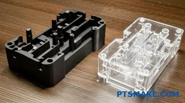
What is the difference between welding plastics and metals?
The real difference lies deep within the material’s structure. It’s about how the atoms and molecules bond. Welding plastics is about encouraging molecular chains to intertwine.
In contrast, welding metals is a more forceful process. It involves creating direct atomic bonds. This requires overcoming natural barriers on the metal’s surface.
Let’s compare the core mechanisms.
| Feature | Plastic Welding | Metal Welding |
|---|---|---|
| Bonding Unit | Polymer Chains | Atoms |
| Mechanism | Melting & Entanglement | Solid-State Bonding |
| Key Process | Intermolecular Diffusion | Atomic Lattice Joining |
| Surface Barrier | Minimal | Oxide Layer |
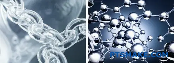
The Science of Plastic Bonding: Molecular Entanglement
When we weld plastics, we apply heat. This energy doesn’t melt the material in the traditional sense. It makes the long polymer chains mobile. Think of it like untangling a ball of yarn.
Once these chains are free to move, we apply pressure. This forces chains from each piece to mix and cross the joint boundary. As the plastic cools, these chains become entangled and lock together. This creates a strong, cohesive bond based on intermolecular forces.
The Mechanics of Metal Welding: Atomic Forging
Metal atoms are locked in a rigid crystalline lattice. They are protected by a tough, non-reactive oxide layer. This layer prevents direct atomic contact. You must break it to form a weld.
This is where techniques like ultrasonic welding excel. High-frequency vibrations generate intense friction and pressure at the joint. This energy causes plastic deformation5 and scours away the oxide layer.
With the barrier gone, pure metal surfaces touch. The applied pressure forces the atoms into intimate contact. They form new, permanent metallic bonds, creating a solid-state weld without melting the bulk material.
| Process Step | Plastic Welding | Metal Welding |
|---|---|---|
| Step 1 | Apply heat to mobilize polymer chains. | Apply pressure and vibration. |
| Step 2 | Apply pressure to mix the chains. | Disrupt and clear the oxide layer. |
| Step 3 | Cool to entangle and lock chains. | Force atoms into contact to form bonds. |
| Result | A mechanically interlocked joint. | A true metallurgical, atomic bond. |
In short, the fundamental difference is how the bond is formed. Plastic welding relies on the physical entanglement of long molecular chains. Metal welding requires breaking surface oxides to forge new, direct bonds between atoms, often in a solid state.
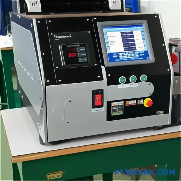
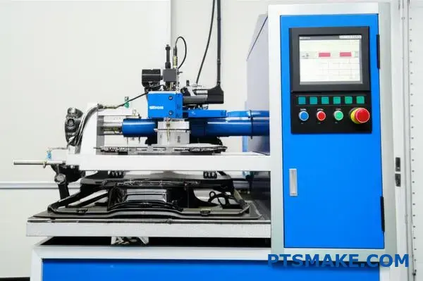
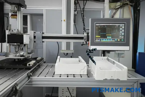
How Are Ultrasonic Welding Machines Categorized?
Choosing the right ultrasonic welding machine isn’t simple. They vary greatly. Key differences lie in their control systems, how they apply force, their power, and their physical setup.
Control System Modes
Weld quality depends heavily on the control mode. Each mode offers a different level of precision.
| Control Mode | Best For | Key Advantage |
|---|---|---|
| Time Mode | Simple, non-critical joints | Consistent cycle times |
| Energy Mode | Parts with slight variations | Consistent energy input |
| Distance Mode | High-precision applications | Precise final part geometry |
Understanding these modes is the first step. It helps match the machine to your specific application needs.
Actuation: The Power Behind the Press
The way a machine applies pressure is crucial. This is called actuation. There are two main types: pneumatic and servo-driven.
Pneumatic systems use compressed air. They are reliable and cost-effective for many jobs. They have been the industry standard for a long time.
Servo-driven systems use electric motors. They offer superior control over force, velocity, and distance. This precision is vital for medical devices or sensitive electronics, where weld consistency is non-negotiable. The actuator6 in these systems allows for complex weld profiles.
| Actuation Type | Pros | Cons |
|---|---|---|
| Pneumatic | Lower initial cost, robust | Less precise control |
| Servo-Driven | High precision, repeatable | Higher initial cost |
Power Levels and Physical Orientation
Power levels, measured in watts, must match the application. Small, delicate parts need low power. Large or difficult-to-weld plastics require much higher power.
Machines also come in different orientations:
- Benchtop: For manual or semi-automated operations.
- Automated: Integrated into larger production lines.
- Handheld: For spot welding or hard-to-reach areas.
At PTSMAKE, we often work with parts that require the precision of servo-driven, automated systems.
Choosing the right ultrasonic welder means understanding its core features. Key factors include control modes, actuation type, power level, and physical orientation. This choice directly impacts weld quality and production efficiency.
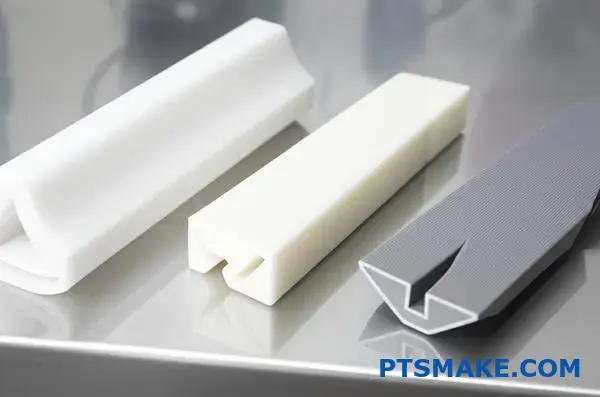
How do you classify different plastic joint designs?
Choosing the right joint design is crucial. It is the foundation for successful ultrasonic welding. A well-designed joint ensures a strong, reliable bond.
Let’s explore three common joint designs. Each has unique features and applications.
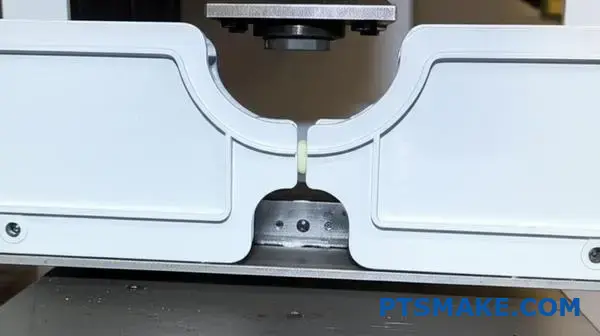
Butt Joint with Energy Director
This is the most common design. A small, triangular ridge on one part focuses the ultrasonic energy. This melts and fuses the plastic precisely.
Shear Joint
The shear joint involves a vertical overlap. The parts melt along a vertical wall as they telescope together. This creates a very strong weld.
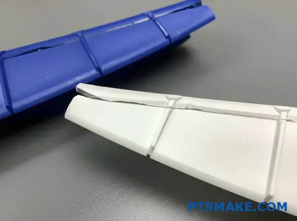
Scarf Joint
A scarf joint uses angled mating surfaces. It is great for self-alignment and produces a clean appearance. It’s often used for cylindrical parts.
Here is a quick comparison:
| Joint Type | Key Feature | Primary Benefit |
|---|---|---|
| Butt Joint | Energy Director | Simplicity & Speed |
| Shear Joint | Vertical Overlap | Maximum Strength |
| Scarf Joint | Angled Surfaces | Self-Alignment |
Diving deeper into these designs reveals their specific strengths. The choice depends entirely on your product’s requirements. At PTSMAKE, we guide clients through this selection process.
Butt Joint: Simplicity and Control
The energy director is key here. Its size and shape control the amount of molten plastic. This makes it ideal for parts that don’t need a perfectly sealed seam. It’s fast and cost-effective.
Shear Joint: Strength and Sealing
This design is our go-to for high-strength needs. The welding action happens over a larger surface area as the parts slide together.
This process is excellent for creating a strong, hermetic seal7. It’s often required for medical devices or sealed electronics. Crystalline plastics benefit greatly from this design.
Scarf Joint: Aesthetics and Alignment
The angled surfaces of a scarf joint help the parts align perfectly during welding. This also helps contain the molten flash internally. The result is a clean, almost invisible seam line. This is great for consumer products where looks matter.
Let’s compare their ideal uses:
| Joint Design | Strength | Seal Quality | Common Application |
|---|---|---|---|
| Butt Joint | Moderate | Basic | Housings, Covers |
| Shear Joint | Very High | Excellent | Medical Devices, Filters |
| Scarf Joint | High | Good | Cylindrical Parts, Pens |
Selecting the right joint design is critical. The butt joint offers speed, the shear joint provides maximum strength and sealing, and the scarf joint excels in alignment and aesthetics. Your application’s specific needs will determine the best choice for successful ultrasonic welding.
What are the primary ultrasonic welding modes and their uses?
Choosing the right ultrasonic welding mode is crucial. It directly impacts weld quality and consistency. Each mode uses a different primary parameter to control the process.
This ensures the right amount of energy is applied. It’s about finding the perfect balance for your specific application.
Key Welding Modes Overview
Here is a quick comparison of the four primary modes. Understanding them helps in optimizing your manufacturing process.
| Mode | Primary Control | Best For |
|---|---|---|
| Time | Weld Duration (Seconds) | Simple, non-critical applications |
| Energy | Energy Input (Joules) | Parts with material variations |
| Collapse/Distance | Part Compression (mm/in) | Precise final assembly height |
| Peak Power | Power Level (Watts) | Delicate, sensitive components |
This table serves as a starting point. The best choice often depends on deeper analysis of the parts and materials involved.
A Deeper Comparison of Control Modes
While the time mode is the simplest, it’s often the least precise. It applies ultrasonic energy for a fixed duration. This method doesn’t account for variations in part dimensions or material properties.
In contrast, the energy mode delivers a specific amount of energy (in joules) to the weld. This is a much better approach for ensuring consistent weld strength. It’s especially useful when dealing with parts that have slight inconsistencies from molding. Materials like amorphous polymers8 often benefit from the precise control of energy mode.
Absolute Distance vs. Peak Power
The absolute distance mode, also known as collapse mode, stops the weld when a specific vertical distance is reached. This is ideal for applications where the final assembly height is critical. It ensures every part has the same final dimension, which is vital for tight-tolerance assemblies we often handle at PTSMAKE.
Peak power mode is more specialized. It terminates the weld cycle once a pre-set power level is achieved. This mode is excellent for protecting delicate internal components from excessive vibration or heat. It’s a fail-safe that prevents damage.
Here’s a look at their control benefits:
| Mode | Control Benefit | Typical Application |
|---|---|---|
| Time | Simplicity, speed | Low-cost consumer goods |
| Energy | Consistent weld strength | Medical devices, automotive parts |
| Distance | Geometric consistency | Electronic enclosures, filters |
| Peak Power | Component protection | Circuit boards, delicate sensors |
From our experience, a combination of modes often yields the best results. For example, using time as a backup limit for an energy-mode weld adds a layer of safety to the process.
Selecting the right ultrasonic welding mode is key to process control. Your choice between Time, Energy, Distance, and Peak Power depends on material consistency, part geometry, and strength requirements. Each offers unique benefits for achieving a perfect weld.
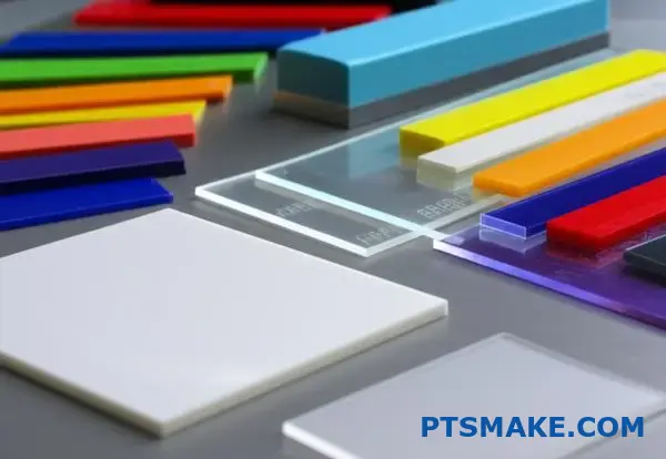
How are materials categorized for ultrasonic welding compatibility?
Understanding material compatibility is crucial for successful ultrasonic welding. A simple chart can be your best starting point. It helps you quickly see which plastics play well together.
Thermoplastic Welding Guide
This guide helps you make initial decisions. Always test your specific material grades. They can have different additives that affect welding.
| Material 1 | Material 2 | Compatibility |
|---|---|---|
| ABS | ABS | Excellent |
| Polystyrene | Polystyrene | Excellent |
| Polycarbonate | ABS | Good |
| HDPE | LDPE | Fair |
| PVC | ABS | Poor/Not Recommended |
This basic framework prevents costly errors. It ensures you select materials that are known to form strong, reliable bonds.
To truly master ultrasonic welding, we must go beyond a simple chart. The real challenge lies in understanding the "why" behind these pairings. It’s about polymer chemistry and physics.
Welding Like-to-Like Materials
Welding identical amorphous polymers is straightforward. Think of ABS to ABS or PC to PC. They have the same molecular structure. They also have the same melting temperature. This allows them to flow and mix easily. This creates a strong, cohesive bond at the joint.
Challenges with Dissimilar Materials
Welding different plastics is much trickier. Success depends on two main factors. You must consider their melting points and chemical structures. A small difference can lead to a weak bond or complete failure.
Melt Temperature Gaps
For a successful weld between dissimilar materials, their melt temperatures should be close. Our internal testing at PTSMAKE suggests a difference of no more than 22°C (40°F) is ideal. A larger gap means one material melts before the other. This prevents proper molecular mixing.
Chemical Incompatibility
Different polymer families often don’t mix. Think of oil and water. For example, welding an amorphous plastic to a semi-crystalline one is very difficult. Their molecular structures are too different to form a strong bond. The Melt Flow Index9 also plays a role here.
| Factor | High Compatibility | Low Compatibility |
|---|---|---|
| Polymer Type | Same (e.g., ABS to ABS) | Different (e.g., ABS to PP) |
| Melt Temp. Diff. | < 22°C (40°F) | > 22°C (40°F) |
| Additive Content | Similar | Dissimilar (e.g., fillers) |
A compatibility chart is a great tool. However, successful ultrasonic welding also requires understanding melt temperatures and chemical structures, especially when joining dissimilar materials.
How does part geometry influence the welding process structure?
Part geometry is not just about aesthetics. It is a critical blueprint for the entire welding process structure. Every curve, wall, and rib influences our decisions.
Factors like wall thickness and part complexity are not minor details. They dictate the essential parameters for a successful weld.
We must analyze these features carefully. This ensures even energy transmission and a strong, reliable bond in the final product.
Key Geometric Influences
| Geometric Factor | Welding Process Consideration |
|---|---|
| Wall Thickness | Determines the required frequency and amplitude. |
| Ribbing/Features | Influences horn design and contact points. |
| Overall Complexity | Dictates the need for custom fixturing. |
This systematic approach prevents common welding defects. It ensures we get the job done right the first time.
Matching the Process to the Part
A successful ultrasonic welding strategy is tailored to the part’s specific geometry. We can’t use a one-size-fits-all approach.
Wall Thickness and Frequency
Thicker walls require lower frequencies (e.g., 20 kHz). This allows the ultrasonic energy to penetrate deeper into the material.
Conversely, thinner, more delicate parts benefit from higher frequencies (e.g., 40 kHz). This provides more controlled energy and prevents damage.
Ribs, Bosses, and Horn Design
Ribs and other features can be both helpful and challenging. They can act as energy directors, focusing the melt.
However, they also create an uneven surface. This demands a custom horn that makes perfect contact across the entire weld area. Without it, energy is lost. The matching of the horn and part is critical for managing acoustic impedance10 to ensure optimal energy flow.
Complex Geometries and Fixturing
The more complex the part, the more critical the fixturing becomes. A well-designed fixture, or nest, must support the part rigidly. It prevents any movement or vibration during the welding cycle.
At PTSMAKE, we often create custom fixtures. They perfectly cradle the part, ensuring energy is directed precisely to the joint interface.
| Challenge | Solution |
|---|---|
| Thick Sections | Use lower frequency horns. |
| Complex Surfaces | Design contoured, custom horns. |
| Delicate Parts | Employ precise, supportive fixtures. |
Part geometry is the starting point for every ultrasonic welding project. It dictates the choice of frequency, the specific design of the horn, and the complexity of the fixture. These elements must work together to ensure a strong, consistent weld.
How do quality control systems for ultrasonic welding differ?
Quality control in ultrasonic welding is not one-size-fits-all. Methods range from simple checks to sophisticated, real-time analysis.
Choosing the right approach is crucial. It ensures your parts meet strict specifications.
Basic vs. Advanced Monitoring
The simplest method is visual inspection. But this only catches surface-level flaws. For deeper assurance, we must look at other methods. Advanced systems monitor the process as it happens.
| Method Type | Primary Focus | Use Case |
|---|---|---|
| Basic Inspection | Post-weld quality | Less critical applications |
| Advanced Monitoring | In-process consistency | High-precision parts |
These systems provide very different levels of confidence in weld quality.
The Limitations of Traditional Testing
For years, destructive testing was the standard. A tensile test, for example, pulls a welded part until it breaks. This gives exact data on its strength.
However, this method has a major flaw. You have to destroy the sample to test it. This means you can only test a small batch percentage. It assumes the entire batch is good based on a few samples.
The Power of In-Process Monitoring
Modern ultrasonic welding systems have changed the game. They use sensors to monitor every single weld in real time. This ensures 100% quality control without destroying parts. It also flags deviations immediately, reducing scrap. The system tracks energy loss due to internal friction, or Hysteresis11, providing a complete picture.
Key Parameters to Track
In our work at PTSMAKE, we focus on a few key metrics. These parameters give us a full picture of weld integrity.
| Parameter | What It Measures | Importance |
|---|---|---|
| Power | Energy consumed during the weld | Indicates material melting and flow |
| Collapse Distance | How much the parts compress | Ensures proper material displacement |
| Frequency | Vibration rate of the horn | Confirms system stability and consistency |
By setting acceptable limits for these parameters, the system can automatically accept or reject each part. This data-driven approach removes guesswork.
Quality control has evolved from post-weld inspection to real-time process monitoring. While basic checks have their place, advanced in-process systems offer superior data, consistency, and reliability for demanding applications. This is key for high-precision manufacturing.
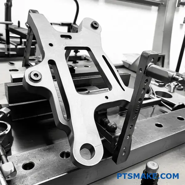
How do you design an effective fixture for a complex part?
Designing a fixture for ultrasonic welding is a precise task. It’s not just about holding a part in place. The fixture is an active component that directly impacts the final weld quality.
Key Fixture Design Principles
Support and Stability
Rigid support directly under the joint area is critical. This prevents energy loss and focuses vibrations where they are needed. Any movement during the process can lead to a failed weld.
Material and Placement
The fixture’s material must not absorb the ultrasonic energy. Consistent part placement is also essential. It ensures every single part is welded under the exact same conditions for repeatability.
| Consideration | Importance |
|---|---|
| Rigid Support | Prevents energy dampening |
| Secure Clamping | Eliminates part movement |
| Material Choice | Transmits energy effectively |
| Consistent Placement | Ensures process repeatability |
Deeper Dive into Fixture Design for Welding
A common mistake is treating the fixture as just a passive holder. In reality, it actively channels the vibrational energy needed for a successful weld. A poorly designed fixture can be the root cause of inconsistent results.
The Critical Role of Support
Think about hammering a nail on a soft, spongy surface. Most of the energy dissipates. The same principle applies here. Without rigid, direct support under the joint, the ultrasonic energy scatters instead of melting the plastic.
Material Science in Fixture Design
We almost always use hard materials like steel, aluminum, or specialized tooling resins. Softer materials act like a cushion, absorbing the high-frequency vibrations and weakening the weld. A material’s acoustic impedance12 is a crucial factor we analyze to ensure maximum energy transfer. In past projects at PTSMAKE, a simple fixture material change, based on our tests, improved final weld strength significantly.
| Material Type | Suitability for Ultrasonic Fixture | Reason |
|---|---|---|
| Hard Metals (Steel, Aluminum) | High | Excellent energy transmission |
| Hard Plastics (Tooling Resins) | Medium | Good for complex shapes, less durable |
| Soft Plastics (Urethane) | Low | Dampens ultrasonic energy |
Effective fixture design for ultrasonic welding hinges on four elements: rigid support, secure clamping, proper material selection, and consistent part placement. Mastering these fundamentals is crucial for achieving a strong, reliable weld and ensuring high-quality production outcomes every single time.
How do you perform a simple destructive test to validate a weld?
How can you be sure a weld is strong enough? You break it. Simple destructive tests are a practical way to get clear answers.
We primarily use two methods. The tensile (pull) test and the peel test. Both involve applying force until the part breaks.
Looking at the broken surface tells you everything. It reveals the true quality of the bond. It’s a direct look at the weld’s integrity.
Here’s a quick comparison of the two tests.
| Test Type | Primary Goal |
|---|---|
| Tensile (Pull) | Measures the ultimate strength of the weld |
| Peel | Checks the bond consistency along the weld line |
A Practical Guide to Tensile and Peel Tests
Let’s break down how to perform these tests and what to look for. These methods give you confidence in your assembly process. At PTSMAKE, we use them to validate new setups for clients.
Conducting a Tensile (Pull) Test
This test is straightforward. You grip the welded parts on opposite sides of the weld. Then, you pull them directly apart until they fail.
The goal is to measure the maximum force the weld can withstand. A higher force usually means a stronger weld. This is a common test for butt joints.
Performing a Peel Test
A peel test is ideal for lap joints. You clamp one part down and pull the other away, peeling it back at a specific angle, often 90 or 180 degrees.
This test helps assess the bond uniformity along the entire length of the weld. It’s great for applications like ultrasonic welding of plastic films or sheets.
What to Look For in the Fracture
The real insight comes from examining the broken pieces. You’re looking for one of two outcomes.
Cohesive Failure: A Sign of a Strong Weld
This is what you want to see. The base material breaks near the weld, but the weld itself remains intact. It proves the weld is stronger than the material it joins. A successful weld results in what we call cohesive failure13.
Adhesive Failure: A Sign of a Weak Weld
This is a red flag. The weld separates cleanly at the interface where the two parts were joined. This indicates a poor bond. The adhesive force was weaker than the material’s internal strength.
| Failure Type | What It Looks Like | Implication for Weld Quality |
|---|---|---|
| Cohesive | Material rips apart, leaving material on both surfaces | Excellent (Weld is stronger than the material) |
| Adhesive | Clean separation at the weld line | Poor (Weld bond is the weak point) |
Tensile and peel tests offer clear, physical proof of weld strength. Analyzing the fracture for cohesive versus adhesive failure is essential for quality control, ensuring the final product performs as designed and meets all critical specifications.
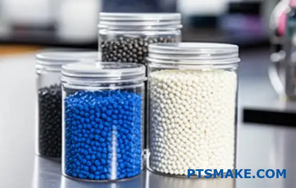
How should you adjust parameters when material batches change?
Material consistency is a common assumption. But even small variations in resin batches can disrupt your process. This is especially true for sensitive operations like ultrasonic welding.
New material batches can behave differently. Key factors include moisture, colorants, and regrind content. Ignoring these can lead to weak welds and failed parts.
Key Resin Variations
| Variation | Potential Impact on Welding |
|---|---|
| Moisture | Voids, porosity, inconsistent weld strength |
| Colorants | Altered energy absorption, inconsistent melting |
| Regrind % | Changes in viscosity, reduced strength |
Adjusting parameters for each new batch is crucial. This ensures consistent quality and avoids costly production issues.
Impact of Resin Variations on Welding
A stable process can quickly become unreliable with a new material batch. You must understand how specific resin properties affect the outcome. Different batches are rarely identical.
Moisture Content
Many polymers are hygroscopic, meaning they absorb moisture. During welding, this moisture turns to steam. This creates voids and weakens the bond. Pre-drying the material is essential, but batch-to-batch absorption rates can still vary.
Colorants and Additives
Colorants, fillers, and other additives change a resin’s properties. For instance, dark pigments may absorb ultrasonic energy differently than light ones. This affects melt rate and flow. Additives like glass fibers can also alter material stiffness and energy transmission.
Regrind Percentage
Using reground material is cost-effective. However, it can alter the material’s viscosity14 and molecular structure. A higher regrind percentage often leads to less consistent weld strength. We’ve seen this in past projects at PTSMAKE.
A Methodical Re-qualification Approach
To manage these variables, a structured re-qualification process is necessary.
| Step | Action | Purpose |
|---|---|---|
| 1. Review | Check the new material’s Certificate of Analysis (CoA). | Identify any specified differences from the previous batch. |
| 2. Initial Test | Weld a small sample using existing parameters. | Quickly assess for major deviations in weld quality. |
| 3. Adjust | If needed, adjust one parameter at a time. | Methodically find the new optimal processing window. |
| 4. Validate | Perform destructive and non-destructive tests. | Confirm the new parameters produce strong, reliable welds. |
Following these steps ensures a smooth transition between material batches. It maintains the integrity of your ultrasonic welding process.
Resin variations like moisture, colorants, and regrind content significantly impact ultrasonic welding. A methodical re-qualification process, including reviewing certifications and performing validation tests, is essential to maintain consistent production quality when switching material batches.
Your weld strength is inconsistent. How do you find the root cause?
When weld strength varies, random guessing is your enemy. You need a structured approach. A problem-solving framework helps you map out all potential causes systematically.
Why Use a Framework?
A tool like the Fishbone (or Ishikawa) diagram is perfect. It helps you brainstorm potential causes without missing anything. It organizes issues into clear categories.
This prevents you from jumping to conclusions. Instead, you can investigate each area methodically to find the true root cause of inconsistent ultrasonic welding strength.
Key Investigation Areas
Here are the main categories to investigate:
| Category | Potential Issues |
|---|---|
| Machine | Parameter drift, worn components |
| Material | Inconsistent resin, moisture |
| Method | Operator variation |
| Environment | Temperature, humidity fluctuations |
Breaking Down the Problem
A framework forces you to look beyond the obvious. In past projects at PTSMAKE, the root cause was often not where the team first looked. It requires discipline to follow the process.
The Machine Bone
Start with your welding machine. Are the parameters—amplitude, weld time, pressure—drifting? We’ve seen worn horns or boosters cause significant issues. Regular calibration is not just a suggestion; it’s essential.
The Material Bone
Material variation is a common culprit. Has the resin batch changed? Is there inconsistent moisture content or regrind percentage? Even slight changes in material can dramatically affect weld quality. You need tight control over incoming materials. Investigating this helps understand the material’s process capability15 for welding.
The People & Method Bone
How consistent is the operator’s process? Are they loading parts the same way every time? Is the training adequate? Sometimes, small, undocumented changes in procedure can lead to big problems down the line.
The Fixture & Environment Bone
Don’t overlook the fixture holding the parts. Is it stable and rigid? A loose fixture allows for vibration, which kills weld consistency. Also, check environmental factors. Drastic changes in temperature or humidity can affect plastic properties and the welding process.
| Fishbone Category | Key Variables to Check |
|---|---|
| Machine | Amplitude, Weld Time, Hold Time, Pressure |
| Material | Resin Type, Moisture Content, Additives, Colorants |
| Fixture | Stability, Wear, Alignment, Clamping Force |
| Environment | Ambient Temperature, Humidity, Air Contaminants |
Using a systematic tool like a Fishbone diagram organizes your investigation. It ensures you check all potential sources of variation—from machine settings to environmental factors—to efficiently pinpoint the true root cause of inconsistent weld strength.
How do you adapt a process for welding a part with thin walls?
Welding parts with thin walls is a precise art. It demands more than just standard settings. The main risk is damaging the part.
You might see warping, cracking, or even burn-through. Success depends on adapting your process carefully.
We focus on controlling every variable. This ensures a strong, clean weld without harming the delicate part.
Key Adaptations for Thin Walls
| Factor | Adaptation | Reason |
|---|---|---|
| Frequency | Use Lower Frequencies | Reduces mechanical stress |
| Horn | Use Contoured Horns | Distributes pressure evenly |
| Fixture | Design Precise Fixtures | Provides full support |
| Joint | Consider Shear Joints | Avoids direct pressure |
A Gentle Approach to Ultrasonic Welding
When dealing with delicate components, brute force is not an option. The entire process must be refined to be gentler. This involves adjusting several key parameters of the ultrasonic welding process.
Lower Frequency for Less Stress
Higher frequencies (e.g., 40 kHz) vibrate faster. This can be too intense for thin walls.
In our experience, switching to a lower frequency, like 20 kHz, reduces mechanical stress on the part. This lower vibration rate is much gentler, preventing fractures. The process involves controlling the welding amplitude16 with extreme precision.
Custom Tooling is Non-Negotiable
Standard, flat horns create pressure points. These can easily damage a thin wall.
We use contoured horns at PTSMAKE. These are designed to match the part’s exact geometry. This distributes force evenly across the surface.
A precise fixture is just as important. It must support the part completely, preventing any flexing or movement during the weld cycle.
| Tooling Element | Function | Benefit for Thin Walls |
|---|---|---|
| Contoured Horn | Matches part surface | Prevents stress concentration |
| Precise Fixture | Supports entire part | Eliminates distortion |
| Shear Joint | Welds along a vertical wall | Avoids direct downward force |
Welding thin parts requires a system approach. Lower frequencies, contoured horns, precise fixtures, and shear joints work together to minimize stress and prevent damage. This ensures a strong, reliable bond.
A competitor achieves a faster cycle time. How would you optimize yours?
To beat a competitor’s cycle time, you must dissect your own process. Every millisecond counts. Let’s focus on the weld cycle itself.
We break it down into key phases. Each phase is an opportunity for optimization. Don’t look at the total time; look at the small steps.
Analyzing Weld Cycle Phases
The entire process has hidden inefficiencies. Identifying them is the first step. Where is time being wasted?
| Phase | Typical Duration (s) | Optimization Potential |
|---|---|---|
| Part Loading | 1.0 – 3.0 | High |
| Clamp / Trigger | 0.2 – 0.5 | Medium |
| Weld Time | 0.1 – 1.0 | High |
| Hold Time | 0.2 – 1.0 | Medium |
| Part Unloading | 1.0 – 3.0 | High |
This breakdown shows where to focus your efforts. Handling often takes more time than the weld itself.
Speeding Up Actuation
The press movement is a key area. Traditional pneumatic presses can have a slight delay. They need time for air to build pressure.
We’ve found servo-driven presses offer a clear advantage. Their actuation is faster and much more precise. This shaves critical fractions of a second from each cycle. The control is also superior.
Optimizing Welding Parameters
Quicker melting is about a balance of amplitude and pressure. Simply increasing power is not the answer. This approach can damage parts or create weak joints.
Our tests show optimizing these settings can cut weld time by 10-15%. This requires careful tuning based on material and geometry. The goal is rapid energy transfer. This transfer is most efficient when the acoustic impedance17 of the horn and the plastic part are well-matched.
The Role of Fixture Design
How quickly can you load and unload parts? This is often the biggest time sink in any ultrasonic welding operation. A poor fixture design is a common culprit.
An improved fixture can make a massive difference. Think about features that guide the part into place. Or consider mechanisms that allow for quicker ejection after the weld.
A well-designed fixture should be both precise and fast to use.
| Fixture Feature | Impact on Cycle Time |
|---|---|
| Poka-yoke (Error-proofing) | Reduces misloads, saves time |
| Quick-release clamps | Speeds up loading/unloading |
| Part ejection assists | Minimizes manual handling |
| Ergonomic design | Reduces operator fatigue and time |
In our experience at PTSMAKE, we work with clients to co-design fixtures that streamline their entire workflow, not just the welding part.
To shorten your weld cycle, analyze each phase meticulously. Faster actuation with servo presses, optimized weld parameters, and smarter fixture design are key strategies. These small changes combine for a significant competitive advantage.
What is the future of ultrasonic welding technology?
The future of ultrasonic welding isn’t just about stronger bonds. It’s about smarter, more precise, and versatile joining processes. We are moving beyond simple plastic assembly.
Hybrid Welding Technologies
Combining ultrasonic energy with other methods is a key trend. This approach tackles materials previously thought unweldable. The goal is superior performance and efficiency.
Welding Advanced Materials
New materials drive innovation. We are now seeing successful ultrasonic welding of composites and even biodegradable plastics. This opens doors for many industries.
| Feature | Traditional Welding | Future Welding |
|---|---|---|
| Control | Amplitude & Pressure | Servo-driven Precision |
| Monitoring | Basic time/energy | Real-time IoT data |
| Materials | Thermoplastics | Composites, Biodegradable |
This evolution is pushing boundaries in manufacturing.
Advanced Servo Controls for Ultimate Precision
Precision is everything in modern manufacturing. The shift from pneumatic to servo-driven ultrasonic welders is a game-changer. Servo controls offer exact management of weld force and velocity.
This means we can achieve incredibly tight tolerances. For parts in the medical or aerospace sectors, this level of control is not just beneficial; it’s essential. In past projects at PTSMAKE, this precision has helped us eliminate micro-fractures in delicate components.
IoT Integration for Smart Manufacturing
IoT is making welding processes intelligent. Sensors integrated into welding systems can monitor every cycle in real-time. They track parameters like amplitude, power, and collapse distance.
This data stream allows for instant adjustments. More importantly, it enables predictive maintenance18 to prevent failures before they happen. This proactive approach drastically reduces downtime and improves overall equipment effectiveness.
| Technology Trend | Key Benefit | Practical Application |
|---|---|---|
| Servo Controls | High Precision & Repeatability | Medical device assembly |
| IoT Integration | Real-time Monitoring | Automotive sensor production |
| Hybrid Welding | Joins Dissimilar Materials | Electronics encapsulation |
| New Materials | Expands Design Freedom | Sustainable packaging |
New Frontiers: Composites and Biodegradables
Ultrasonic welding is also adapting to new material challenges. Joining carbon-fiber composites or biodegradable polymers used to be difficult.
Now, advancements in energy direction and tool design make it possible. This is crucial for industries like automotive, which seek lightweight strength, and packaging, which is moving toward sustainability. It expands what designers can create.
The future of ultrasonic welding is intelligent and precise. With servo controls, IoT integration, and the ability to join new materials, the technology is becoming more vital than ever for high-spec manufacturing.
Unlock Precision Ultrasonic Welding Solutions with PTSMAKE
Looking to elevate your ultrasonic welding projects? Contact PTSMAKE today for expert support, custom solutions, and unbeatable reliability—request a quote or send your inquiry now! Let’s achieve flawless results together, from prototypes to production, with world-class precision and service.

Gain a deeper understanding of how molecular bonds create heat under ultrasonic stress. ↩
Learn the physics of how ultrasonic waves transfer efficiently from the horn to the parts. ↩
Explore how different molecular structures impact your project’s manufacturing process. ↩
Discover how cooling rates influence polymer structure and the final strength of your welded parts. ↩
See how this permanent shape change enables strong metal bonds without melting. ↩
Learn how different actuator types impact precision and quality in your manufacturing process. ↩
Discover how to achieve airtight seals for critical components in your next project. ↩
Learn how different polymer structures affect the ultrasonic welding process and your choice of welding mode. ↩
Discover how this metric influences material flow and weld strength. ↩
Understand this concept to see how energy is efficiently transferred from the welder to your part. ↩
Understand how this material property impacts energy transfer and final weld integrity in ultrasonic welding. ↩
Understand how material properties affect energy transfer in welding. ↩
Understand the science behind material bonding and why this failure mode signals a superior, reliable weld. ↩
Discover how this key material property influences weld formation and overall strength. ↩
Learn how this metric predicts if your process can consistently meet quality specifications. ↩
Learn how this key parameter influences weld strength and prevents damage to delicate components. ↩
Discover how this property impacts energy transfer and weld quality in our complete guide. ↩
Learn how this data-driven approach can prevent equipment failure and boost your production efficiency. ↩