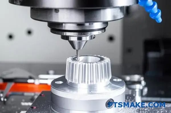
You’re specifying tight tolerances on your CNC machined parts, but are you getting the precision you actually need? Many engineers over-specify tolerances without understanding the cost and lead time impact, while others under-specify and face costly assembly failures.
Tight tolerance CNC machining achieves dimensional accuracy typically within ±0.0001" to ±0.005", requiring specialized equipment, advanced tooling, and rigorous quality control processes that significantly impact cost and production time.
I’ve worked on projects where a single tolerance decision made the difference between a successful product launch and a costly redesign. The challenge isn’t just achieving tight tolerances – it’s knowing when you need them, how to design for them, and what they’ll cost you. This guide covers everything from material selection and design optimization to inspection methods and cost management strategies that will help you make smarter tolerance decisions for your next precision manufacturing project.
Why Tight Tolerance CNC Machining Matters in Critical Industries?
Have you ever seen a flawless design on paper fail in assembly due to a microscopic deviation? That single imperfection can halt production, skyrocket costs, and compromise the entire project’s integrity.
Tight tolerance CNC machining is critical because it ensures components fit and function with absolute precision. This directly guarantees the safety, reliability, and performance of final products in high-stakes industries like aerospace and medical, where even the smallest error can have catastrophic consequences.
The Unforgiving Demands of Critical Sectors
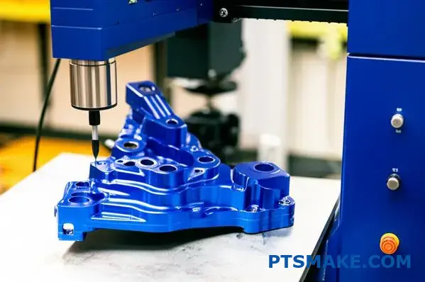
In many industries, "close enough" is simply not an option. For sectors where performance and safety are paramount, precision isn’t a goal—it’s the baseline requirement. This is where tight tolerance CNC machining becomes the cornerstone of manufacturing. It’s the difference between a part that works and a part that works flawlessly under extreme conditions for its entire intended lifespan.
Aerospace: Where Failure is Not an Option
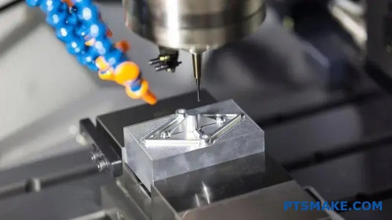
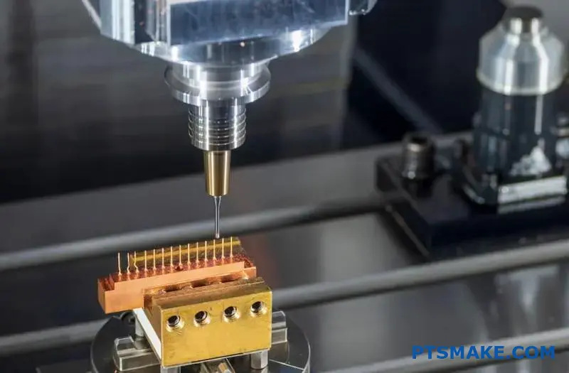
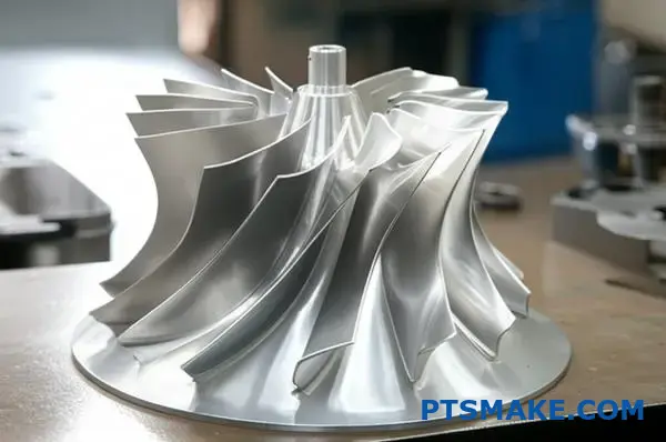
In aerospace, components are subjected to extreme temperatures, pressures, and stresses. Think about a turbine blade in a jet engine spinning at thousands of RPM or a critical actuator in a landing gear system. A deviation of even a few micrometers can lead to premature material fatigue, reduced fuel efficiency, or catastrophic failure. In our past projects at PTSMAKE, we’ve machined components for aerospace clients where the tolerance for certain features was tighter than the width of a human hair. This level of precision ensures that every part in a complex assembly bears its intended load without creating unforeseen stress points. The entire system’s integrity depends on the perfection of its individual parts.
Medical Devices: Precision for Life
The medical field demands an even higher standard of precision. For implantable devices like pacemakers or artificial joints, the fit and finish must be perfect to ensure biocompatibility and long-term function within the human body. Surgical instruments also require incredibly tight tolerances to perform delicate procedures effectively and safely. Any surface imperfection could harbor bacteria, and any dimensional inaccuracy could mean the difference between a successful surgery and a critical complication. We use a system of Geometric Dimensioning and Tolerancing (GD&T)1 to ensure every feature is precisely controlled.
| Industry | Critical Application | Typical Tight Tolerance Range (inches) | Consequence of Failure |
|---|---|---|---|
| Aerospace | Turbine Blades | ±0.0005" to ±0.001" | Engine failure, loss of performance |
| Medical | Orthopedic Implants | ±0.0002" to ±0.0005" | Device rejection, surgical complications |
| Automotive | Fuel Injector Nozzles | ±0.0004" to ±0.001" | Reduced fuel efficiency, increased emissions |
| Semiconductor | Wafer Handling Robots | ±0.0001" to ±0.0005" | Damaged wafers, production loss |
This table, based on our experience with clients in these fields, shows just how narrow the margin for error is.
The Domino Effect of Tolerance Failures
Failing to meet tight tolerances isn’t just a minor quality issue; it triggers a chain reaction of problems that can impact everything from the assembly line to the end-user’s safety. The costs associated with these failures go far beyond simply remaking a single part. It involves lost time, wasted material, and a significant blow to a project’s budget and timeline. In the most severe cases, it can damage a company’s reputation and lead to serious liability issues.
Assembly Nightmares and Mismatched Parts
The most immediate consequence of poor tolerance control is assembly failure. When one component is even slightly out of spec, it may not fit with its mating part. This can bring an entire assembly line to a halt. In a past collaboration with an automotive client, we saw how a supplier’s batch of brackets with holes drilled just 0.002" off-center caused a two-day shutdown. The cost of the production delay far exceeded the cost of the parts themselves. This is why a reliable partner for tight tolerance CNC machining is essential for maintaining a smooth and efficient production workflow. At PTSMAKE, we’ve built our reputation on preventing these kinds of "line-down" situations for our clients.
Compromised Performance and Reduced Lifespan
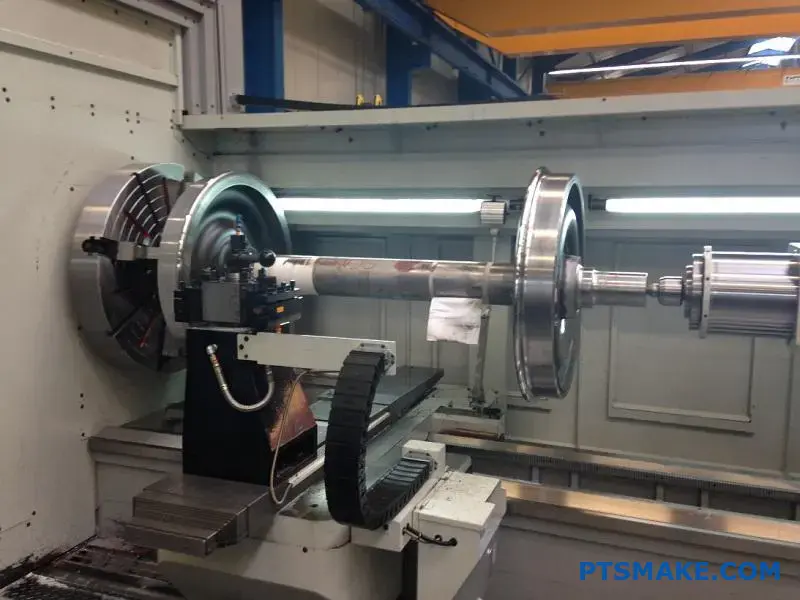
Even if out-of-spec parts can be forced to fit together, the final product’s performance and longevity will be compromised. Imagine a shaft and bearing assembly where the clearance is too large. This will cause excessive vibration, leading to accelerated wear and tear and eventual premature failure. In high-performance machinery, this reduced efficiency translates to higher energy consumption and lower output. Over time, these seemingly minor imperfections compound, drastically shortening the product’s operational lifespan and increasing maintenance costs for the end-user.
| Tolerance Issue | Immediate Impact | Long-Term Consequence |
|---|---|---|
| Hole diameter too small | Bolt or pin won’t fit | Assembly halt, rework costs |
| Surface not flat enough | Poor seal, fluid/gas leaks | Reduced efficiency, potential system failure |
| Feature misaligned | Mating parts don’t connect | Increased stress, fatigue, and wear |
| Overall dimension too large | Part won’t fit in housing | Scrapped parts, project delays |
These examples highlight how a single flaw in precision machining can cascade into much larger operational and financial problems.
In critical industries, tight tolerance CNC machining is not a luxury but a fundamental necessity. It’s the invisible force that guarantees a jet engine’s reliability, a medical implant’s safety, and an automotive system’s performance. As we’ve seen, overlooking precision leads to a cascade of problems, from assembly line stoppages and reduced product lifespan to severe safety hazards. The integrity of the final product truly begins with the precision of its smallest components.
Material Selection and Its Impact on Achieving Tight Tolerances.
Have you ever picked the perfect material on paper, only to watch it fail to hold tolerances on the machine? This frustrating setback costs both time and money, derailing project timelines.
The right material choice is foundational for successful tight tolerance CNC machining. Factors like thermal stability, hardness, and machinability directly dictate whether a part can hold precise dimensions without warping, causing excessive tool wear, or deforming under the stress of machining.
The Core Three: Machinability, Stability, and Expansion
When we aim for tolerances measured in microns, the material itself becomes an active variable in the process, not a passive block of metal or plastic. At PTSMAKE, we’ve learned that a material’s inherent properties can either help or hinder our ability to deliver on high-precision requirements. Understanding three core characteristics is non-negotiable.
What is Machinability?
Machinability isn’t just about how hard a material is. It’s a broader concept that describes how easily it can be cut, how it affects tool life, and the surface finish it produces. A material with good machinability, like Aluminum 6061, allows for faster cutting speeds and results in less tool wear. Conversely, materials like Inconel or Titanium are notoriously difficult to machine. They generate immense heat and wear down cutting tools rapidly, making it a challenge to maintain consistent dimensions throughout a production run. This directly impacts the ability to perform tight tolerance cnc machining reliably.
Why Thermal Expansion Matters
Every material expands when heated and contracts when cooled. The rate at which it does this is its coefficient of thermal expansion (CTE). During CNC machining, both the workpiece and the cutting tool heat up significantly. A material with a high CTE, like many plastics, will expand more noticeably. If this isn’t accounted for, a part measured as perfect while warm on the machine may fall out of tolerance once it cools to room temperature. This subtle change can be the difference between success and failure. The effect of anisotropy2 in certain materials can further complicate how they react to thermal changes.
The Goal: Dimensional Stability
Dimensional stability is a material’s ability to retain its original size and shape over time and under varying environmental conditions. Some materials, especially certain plastics, can absorb moisture from the air, causing them to swell slightly. Others might have internal stresses from their manufacturing process, which are released during machining, leading to warping. For parts that need to hold tight tolerances for years, choosing a dimensionally stable material like PEEK or Stainless Steel is crucial.
| Material | Machinability Rating (vs. 1212 Steel) | Thermal Expansion (CTE, µm/m-°C) | Key Consideration for Tolerances |
|---|---|---|---|
| Aluminum 6061-T6 | High | 23.6 | Good stability, but can be "gummy." |
| Stainless Steel 304 | Medium | 17.3 | Work hardens; requires sharp tools. |
| PEEK | Medium | ~55.0 | High CTE; requires cooling strategies. |
| Titanium (Ti-6Al-4V) | Low | 8.6 | Poor thermal conductivity; high tool wear. |
Common Material Families and Their Challenges
Choosing the right material involves balancing the end-use application requirements with manufacturability. In my experience with diverse projects, I’ve seen how these choices play out in real-world scenarios, especially when pushing the limits of precision.
Metals: The Go-To for Stability
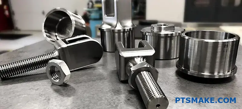
Metals are often the first choice for high-precision applications due to their strength, stiffness, and general dimensional stability.
- Aluminum Alloys (e.g., 6061, 7075): These are fantastic for prototyping and production parts. They are lightweight and have excellent machinability. However, they are softer and have a relatively high CTE compared to steel, which must be managed with coolants and careful toolpath strategies.
- Stainless Steels (e.g., 303, 304, 316): Known for corrosion resistance and strength. They are generally more difficult to machine than aluminum because they tend to work-harden. This means the material becomes harder as it’s being cut, which puts more stress on the tool and can affect the final dimensions if not handled correctly.
- Hard Metals (e.g., Tool Steels, Titanium): These offer incredible performance but present the biggest machining challenges. They require specialized tooling, slower cutting speeds, and robust machines to prevent vibration. Achieving tight tolerances in these materials requires deep expertise and process control. Our team often collaborates with clients early on to confirm if such a material is truly necessary or if a more machinable alternative can meet the design intent.
Plastics: A Balance of Properties
Plastics offer unique benefits like chemical resistance and light weight, but they come with their own set of rules for tight tolerance cnc machining.
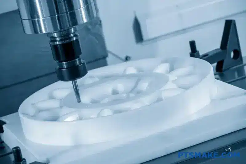
- The Warping Problem: Many engineering plastics, like Delrin (Acetal) or Nylon, have internal stresses from their extrusion or casting process. As layers of material are removed during machining, these stresses are released, causing the part to warp or bow. We mitigate this through techniques like rough machining, letting the part rest and stabilize, and then performing a final, light finishing pass.
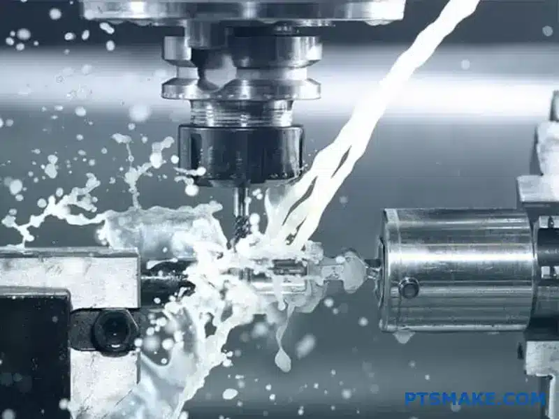
- Managing Heat: Plastics are poor thermal conductors. Heat generated from cutting doesn’t dissipate quickly, which can cause the material to melt locally or expand significantly. This can lead to inaccurate dimensions and a poor surface finish. Using sharp tools, appropriate coolants, and optimized cutting parameters is essential.
| Material Group | Common Pitfall | PTSMAKE’s Mitigation Strategy |
|---|---|---|
| Soft Metals (Al) | Gummy texture, poor finish | Use high-shear tooling and proper lubrication. |
| Hard Steels (SS) | Work hardening, tool wear | Employ rigid setups, sharp tools, and consistent feed rates. |
| Engineering Plastics | Warping, melting | Stress-relieve material, use air or coolant, sharp tools. |
| Hard Metals (Ti) | High heat, extreme tool wear | Utilize high-pressure coolant and specialized tool coatings. |
Material selection is a critical first step in achieving tight tolerances. Your choice directly impacts the entire machining process, from tool selection to cycle time. Understanding how properties like machinability, thermal expansion, and dimensional stability interact is essential. Recognizing common pitfalls, such as warping in plastics or work hardening in steels, allows for proactive strategies that prevent costly errors. Ultimately, a well-informed material decision lays the groundwork for a successful, high-precision component that meets every specification.
Design Considerations for Engineers: Optimizing for Tight Tolerance Machining.
Ever designed a part with perfect tolerances on paper, only to find it’s a manufacturing nightmare that shatters the budget?
Optimizing for tight tolerance machining involves strategically applying tight tolerances only to critical features, simplifying geometry by avoiding thin walls and sharp corners, and collaborating with your machinist early. Clear communication and proper GD&T in drawings are key for success.
The "Less is More" Philosophy in Tolerancing
One of the most common hurdles I see engineers face is the instinct to over-tolerance a part. It seems logical—tighter tolerances mean a better part, right? Not always. Every tightened tolerance adds manufacturing steps, increases cycle time, requires more specialized inspection equipment, and consequently, drives up costs. A part with unnecessarily tight tolerances across all features can easily cost double or triple what a strategically toleranced version would.
The key is to differentiate between critical and non-critical features. Critical features are those that directly impact the part’s fit, form, and function—mating surfaces, bearing bores, alignment pin holes. These are where you should invest your tolerance budget. For non-critical surfaces, such as the outer housing of a component, a standard, looser tolerance is perfectly acceptable and far more economical. Before finalizing your drawing, ask yourself for each dimension: "Does this feature’s precision truly affect the assembly’s performance?" This simple question can save significant time and money.
Geometry and Material Selection
The geometry of a part has a massive impact on our ability to achieve tight tolerances. Two common culprits that make a machinist’s job difficult are thin walls and sharp internal corners.
Challenges with Thin Walls
Thin walls are prone to vibration and chatter during machining, which makes holding a precise dimension extremely difficult. They can also warp from the heat and stress induced by cutting tools. We often have to use lower cutting speeds and take shallower passes, which increases machining time. A good rule of thumb is to maintain a wall thickness-to-height ratio that provides enough rigidity for stable machining.
The Issue with Sharp Internal Corners
A standard rotating end mill is round, meaning it naturally creates a radius in an internal corner. Achieving a perfectly sharp 90-degree internal corner is often impossible with conventional CNC milling. It requires secondary processes like Electrical Discharge Machining (EDM), which adds a completely new manufacturing step and significant cost. Instead, design a small radius in these corners that matches a standard tool size. It’s a small design change that makes the tight tolerance cnc machining process much smoother.
Material choice is also fundamental. Some materials are inherently more stable and easier to machine to high precision than others. The material’s thermal stability and hardness play a huge role. For instance, certain plastics might exhibit anisotropy3, affecting how they respond to machining forces.
| Material Group | Machinability for Tight Tolerances | Stability | Common Examples |
|---|---|---|---|
| Aluminum Alloys | Excellent | Good | 6061, 7075 |
| Stainless Steels | Good to Moderate | Excellent | 304, 316, 17-4 PH |
| Tool Steels | Difficult | Excellent | A2, D2 |
| Engineering Plastics | Moderate | Varies | PEEK, Delrin (Acetal) |
Early Collaboration: Your Secret Weapon
The single most effective way to optimize a design for tight tolerance machining is to talk to your manufacturing partner early in the design process. A Design for Manufacturability (DFM) review can uncover potential issues before they become expensive problems. In our work at PTSMAKE, we frequently collaborate with engineering teams to provide feedback that simplifies production without compromising function.
I recall a project involving a complex medical device component. The initial design had several deep pockets with very tight profile tolerances and sharp internal corners. On paper, it was perfect. In reality, it would have required custom long-reach tooling and extensive EDM work, making the cost prohibitive. By collaborating with the design engineer, we suggested minor changes: increasing the corner radii slightly to allow for standard tooling and opening up a tolerance on a non-critical internal surface. These small adjustments reduced the machining time by over 40% and brought the part well within budget, all while maintaining the critical functional requirements. This is the power of early partnership.
Communicating Tolerances Effectively on Drawings
Your CAD drawing is the ultimate source of truth for the machinist. How you communicate your requirements on that drawing determines the final outcome.
The Language of GD&T
Geometric Dimensioning and Tolerancing (GD&T) is the universal language for specifying tolerances. It goes beyond simple +/- dimensions to control the feature’s form, orientation, and location. Using GD&T properly removes ambiguity. Instead of just a tight tolerance on a hole’s diameter, you can control its perpendicularity to a mating face or its true position relative to other features. This ensures the part functions as intended within the assembly.
Best Practices for Clear Callouts
Your drawing should be a clear and concise instruction manual. Here are a few tips:
- Define Datum Features: Clearly establish your datum reference frame (A, B, C). All critical features should be dimensioned from these datums to reflect how the part is located in its final assembly.
- Avoid Tolerance Stacking: Dimension features from a common datum whenever possible to avoid the accumulation of tolerances between features.
- Specify Surface Finish: A tight tolerance often goes hand-in-hand with a fine surface finish requirement. Make sure to include finish callouts (e.g., Ra 1.6 µm) on critical surfaces.
Finally, provide context. A simple note on the drawing explaining a feature’s function—like "Mates with bearing P/N XXX"—gives the machinist valuable insight. It helps us understand the design intent and prioritize the most critical aspects of the part during both machining and inspection.
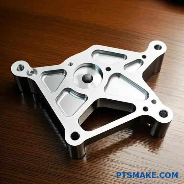
Achieving successful tight tolerance machining begins long before a machine is turned on. It starts with a smart design philosophy: apply tight tolerances only where they are functionally essential. By simplifying geometry, choosing appropriate materials, and avoiding manufacturability traps like sharp corners, you create a solid foundation. Most importantly, fostering an early, collaborative partnership with your machinist and using clear, context-rich drawings transforms a theoretical design into a perfectly executed, high-precision component that meets both spec and budget.
Cost and Lead Time Implications of Tight Tolerance Requirements.
Have you ever specified a tight tolerance just to be safe, only to see the quote come back shockingly high? It’s a common scenario that can derail project budgets before they even start.
Tighter tolerances significantly increase costs and lead times by requiring more advanced machinery, slower machining speeds, rigorous inspection processes, and higher scrap rates. Understanding this trade-off is crucial for optimizing your design for manufacturability and staying within budget.
The Root Causes of Increased Costs
The connection between tight tolerances and high costs isn’t arbitrary; it’s rooted in the fundamental physics and processes of manufacturing. When you shrink the acceptable margin of error, you create a ripple effect that touches every stage of production. It’s not simply about telling a machine to be more precise; it’s about creating an entire environment where that precision is possible and repeatable.
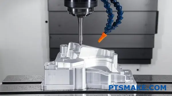
Slower Machining Cycles
To achieve a high degree of precision, a CNC machine can’t operate at its maximum speed. Machinists must reduce feed rates and the depth of each cut. This minimizes tool deflection, vibration, and heat buildup—all of which can push a dimension out of tolerance. A part that might take 10 minutes to machine with standard tolerances could take 30 minutes or more when requirements are tightened. Since machine time is a primary driver of cost in any shop, this tripling of time directly translates to a much higher price.
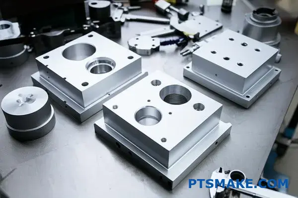
Specialized Fixturing and Tooling
Standard vises and chucks are often insufficient for tight tolerance CNC machining. Parts may require custom-designed fixtures to hold them with absolute rigidity, ensuring they don’t shift even a fraction of a millimeter during the process. Furthermore, achieving ultra-fine surface finishes or dimensions often requires specialized, high-performance cutting tools that are more expensive and have a shorter lifespan. These non-recurring engineering (NRE) costs for fixtures and the ongoing expense of premium tools are factored directly into your quote.
The Inevitability of Higher Scrap Rates
When the window of acceptability is very small, more parts will inevitably fall outside it. A slight change in ambient temperature causing thermal expansion, a minuscule amount of tool wear, or a subtle material inconsistency can be enough to scrap a part. In past projects at PTSMAKE, we’ve seen scrap rates for standard tolerance parts remain below 2%. For parts with extremely tight tolerances, it’s not uncommon for that rate to climb to 10% or higher. This predictable loss must be priced into the job, meaning you pay not only for the good parts but also for the anticipated failures. The entire process relies on the principles of Metrology4 to verify compliance.
A quick comparison highlights these differences starkly:
| Factor | Standard Tolerance (±0.1mm) | Tight Tolerance (±0.01mm) |
|---|---|---|
| Machining Time | Normal | 2x – 4x Slower |
| Inspection Method | Calipers, Micrometers | CMM, Laser Scanners |
| Typical Scrap Rate | < 2% | 5% – 15%+ |
| Tooling Needs | Standard | High-Performance / Custom |
| Operator Skill | Skilled Machinist | Senior Specialist |
Strategies for Balancing Precision, Cost, and Time
While some components absolutely require high precision, the key to cost-effective design is knowing when and where to apply it. Over-specifying tolerances is one of the most common and costly mistakes in product development. Adopting a more strategic approach can yield significant savings in both cost and lead time without compromising the final product’s function.
Embrace Functional Dimensioning
Analyze your design and ask yourself: which features are truly critical? Tight tolerances should be reserved exclusively for mating surfaces, bearing bores, alignment features, and other interfaces where fit is essential for performance. For non-critical surfaces, such as the outside of a housing or a decorative feature, specify the machine shop’s standard tolerance. This simple act of relaxing tolerances on non-functional dimensions can drastically reduce machining time and complexity. In one instance, a client came to us with a part where every dimension had a tight tolerance. After a DFM review, we identified that only two features were critical. By relaxing the others, we reduced the part cost by nearly 50%.
The Power of Early Collaboration
The single most effective strategy is to engage with your manufacturing partner early in the design phase. A discussion before a design is finalized can uncover opportunities for cost savings that are impossible to implement later. At PTSMAKE, we often provide Design for Manufacturability (DFM) feedback to help clients optimize their parts. We can advise on material selection, suggest minor design tweaks that make a part easier to machine, and help you determine which tolerances are truly necessary versus those that are "nice-to-haves." This collaborative approach turns the manufacturing process from a simple transaction into a partnership aimed at achieving the best possible outcome for your budget and timeline.
Use GD&T Wisely
Geometric Dimensioning and Tolerancing (GD&T) is a powerful tool when used correctly. Instead of applying a tight linear tolerance to a whole surface, you can use a flatness or profile control to manage the critical aspect of the feature while allowing for more variation elsewhere. This gives the machinist more operational freedom, which can lead to faster cycle times and lower costs, all while ensuring the part functions as intended.
Here is a breakdown of different approaches to tolerancing:
| Tolerance Approach | Pros | Cons | Best For… |
|---|---|---|---|
| Standard Tolerances | Low cost, fast production, simple inspection. | Not suitable for precision fits or assemblies. | General components, non-mating surfaces. |
| Selective Tolerancing | Balances cost with performance, highly efficient. | Requires careful DFM analysis and planning. | Most mechanical assemblies with critical interfaces. |
| Uniformly Tight Tolerances | Guarantees precision across the entire part. | Extremely expensive, long lead times, high risk. | Mission-critical aerospace, medical implants, optical instruments. |
In summary, tight tolerances are a direct driver of higher costs and longer lead times in CNC machining. This is due to slower machine cycles, the need for specialized tooling and inspection, and increased scrap rates. The most effective strategy to manage these factors is to apply tight tolerances only where they are functionally critical. Early collaboration with your manufacturing partner is key to optimizing your design for both performance and budget, avoiding the unnecessary expense of over-specification.
Inspection and Quality Control Methods for Tight Tolerance CNC Parts?
Ever received a batch of CNC parts only to find they don’t meet the specified tolerances? The delays, costs, and sheer frustration can bring a project to a grinding halt.
Verifying tight tolerance CNC parts involves advanced tools like CMMs, laser scanners, and optical comparators. Robust quality control relies on rigorous process control, detailed documentation, traceability, and statistical methods like SPC to ensure every part is identical and meets specifications.
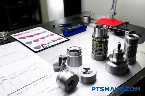
Advanced Inspection Techniques: Beyond Calipers and Micrometers
When dealing with tolerances measured in microns, traditional tools like calipers and micrometers often don’t provide the necessary accuracy or comprehensive data. This is where advanced metrology comes into play. It’s not just about confirming a single dimension; it’s about verifying the entire part’s geometry against the CAD model. In our experience at PTSMAKE, integrating these advanced methods is non-negotiable for producing reliable high-precision parts.
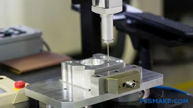
Coordinate Measuring Machines (CMMs)
A CMM is the gold standard for dimensional inspection. It uses a highly sensitive probe to touch various points on a part’s surface, recording their X, Y, and Z coordinates. This data is then used to verify complex features, from the true position of a hole to the flatness of a surface. For parts with intricate geometries and strict Geometric Dimensioning and Tolerancing (GD&T)5 callouts, the CMM provides the definitive pass/fail verdict. It’s slower than other methods but offers unparalleled accuracy.
Laser and 3D Scanners
For parts with complex curves or organic shapes, non-contact measurement is often the best approach. Laser scanners and structured-light 3D scanners capture millions of data points from the part’s surface in seconds, creating a dense point cloud. This cloud is then compared to the original CAD file, generating a color map that instantly highlights any deviations. This method is incredibly fast and provides a complete surface analysis, making it ideal for verifying things like turbine blades or custom medical implants.
Optical Comparators
An optical comparator, or profile projector, is a classic but still incredibly useful tool. It projects a magnified shadow of a part onto a screen, allowing for quick comparison against a scaled overlay of the drawing. It excels at inspecting 2D features like radii, chamfers, thread forms, and gear tooth profiles. While it doesn’t provide 3D data, it’s a fast and effective way to check critical profile tolerances on a production floor.
| Inspection Technique | Best For | Key Advantage | Common Limitation |
|---|---|---|---|
| CMM | Complex geometries, prismatic parts, high-accuracy validation | Unmatched precision and repeatability for GD&T | Slower measurement cycle, requires a controlled environment |
| Laser/3D Scanner | Freeform surfaces, reverse engineering, rapid surface analysis | Extremely fast data capture, provides a complete surface map | Lower accuracy than a CMM for individual point measurements |
| Optical Comparator | 2D profiles, threads, chamfers, small features | Quick and easy visual inspection on the shop floor | Limited to 2D measurements, reliant on operator interpretation |
Building Quality In: Process Control and Data-Driven Methods
Inspection is crucial, but it’s a reactive measure—it catches defects after they’ve already happened. The ultimate goal in tight tolerance CNC machining is to prevent defects from occurring in the first place. This requires a proactive approach centered on robust process control, meticulous documentation, and the intelligent use of data. You can’t just inspect quality into a part; you have to build it in from the very first step.
The Foundations: Process Control, Documentation, and Traceability
These three elements form the backbone of any reliable quality system.
- Process Control: This involves actively monitoring and controlling every variable in the manufacturing process. It’s not just about the CNC machine’s settings. It includes regular machine calibration, monitoring tool wear and replacing tools before they fail, maintaining consistent coolant concentrations, and even controlling the temperature and humidity of the workshop. A stable process is a predictable process.
- Documentation: If it isn’t documented, it didn’t happen. From the certificate of conformance for the raw material to the First Article Inspection Report (FAIR) and the final inspection results, every step must be recorded. This creates a detailed history for every production run, which is invaluable for analysis and essential for clients in regulated industries like aerospace and medical.
- Traceability: This is the result of good documentation. It gives us the ability to trace a finished part all the way back to its raw material batch, the machine it was run on, the operator who ran it, and the date it was produced. If a problem ever arises, traceability allows us to quickly isolate the root cause and limit the impact.
The Power of Data: Statistical Process Control (SPC)
Statistical Process Control (SPC) is a powerful methodology that uses statistical tools to monitor and control a process. Instead of just checking if a part is "in spec" or "out of spec," SPC helps us understand the natural variation within a process and identify when something is changing.
Using tools like control charts, we can track critical dimensions over time. These charts have upper and lower control limits that represent the natural capability of the process. As long as the measurements fall randomly between these limits, the process is stable. But if we see a trend—like measurements consistently drifting towards one limit—it signals a problem before any bad parts are made. This allows us to intervene, perhaps by adjusting an offset or changing a worn tool, keeping the process centered and capable of holding tight tolerances.
| Quality Element | Purpose | Example in Practice |
|---|---|---|
| Process Control | To minimize variation and ensure process stability. | Calibrating a CNC machine’s axes every six months. |
| Documentation | To create a verifiable record of the entire manufacturing journey. | Attaching a material certification sheet to the work order. |
| Traceability | To link a finished part to its complete production history. | Engraving a unique serial number on each part. |
| SPC | To monitor the process in real-time and prevent defects proactively. | Using an X-bar chart to track the diameter of a machined pin. |
Achieving tight tolerance CNC machining requires a dual strategy. It relies on advanced inspection tools like CMMs and laser scanners for final verification, but more importantly, it depends on embedding quality into the manufacturing process itself. Through rigorous process control, detailed documentation, and data-driven methods like Statistical Process Control, we shift the focus from simply detecting defects to actively preventing them. This holistic approach is the only way to ensure consistent, reliable precision in every part produced.
Comparing CNC Machining to Other Manufacturing Methods for Tight Tolerances.
Ever wondered if CNC is always the best choice for precision? Or if another method could achieve the same tight tolerances for your specific part design more effectively?
CNC machining is superior for achieving tight tolerances on complex, low-to-mid volume parts, especially with metals. Injection molding is ideal for high-volume plastic parts, while 3D printing excels at rapid prototyping where tolerances are less critical. Manual methods suit simple, one-off jobs.
When engineers approach us at PTSMAKE, a common question is how to choose the right manufacturing process. While our specialty is tight tolerance CNC machining, the best answer always depends on the project’s specific goals. Let’s break down the key differences between CNC and two other popular methods: 3D printing and injection molding.
CNC Machining vs. 3D Printing (Additive Manufacturing)
These two methods are often seen as rivals, but they serve very different primary purposes, especially when it comes to precision.
Tolerance and Surface Finish
3D printing, or additive manufacturing, builds parts layer by layer. This process inherently creates a stepped surface and can lead to internal stresses or warping, making it difficult to hold tolerances tighter than ±0.1 mm (±0.004"). CNC machining is a subtractive process that carves from a solid block, resulting in superior surface finishes and the ability to easily achieve tolerances of ±0.025 mm (±0.001") or even tighter.
Material Integrity and Strength
A part machined from a solid block of metal or plastic retains its original material properties. This means it has excellent, uniform strength. 3D printed parts, due to their layered construction, can have weaker bonds between layers, leading to anisotropic properties where the part is weaker in one direction. For functional parts that require high strength and reliability, the isotropic6 nature of a CNC machined component is a significant advantage.
Here’s a quick comparison:
| Feature | CNC Machining | 3D Printing (FDM/SLA) |
|---|---|---|
| Typical Tolerance | ±0.025 mm (±0.001") | ±0.1 mm (±0.004") |
| Surface Finish | Excellent (as-machined) | Good (often needs post-processing) |
| Material Strength | Excellent (Isotropic) | Good (Anisotropic) |
| Best Use Case | Functional prototypes, production parts | Form/fit prototypes, complex internal geometries |
CNC Machining vs. Injection Molding
This comparison is less about precision capability and more about volume and cost. Both can produce highly precise parts, but their economic models are worlds apart. Injection molding requires a significant upfront investment in creating a mold, which can cost thousands of dollars. However, once the mold is made, the cost per part is extremely low, making it perfect for mass production. CNC machining has minimal setup costs, making it ideal for prototyping and low-to-mid volume production runs.
Beyond the popular alternatives, it’s also useful to compare CNC with more traditional or specialized methods to understand the full manufacturing landscape. This helps in making informed decisions, especially when balancing cost, speed, and precision.
CNC Machining vs. Traditional Manual Machining
Before computers, skilled machinists created parts manually using lathes, mills, and drill presses. While this craft is still valuable, it has clear limitations compared to CNC.
Repeatability and Complexity
A human operator, no matter how skilled, cannot match the perfect repeatability of a computer-controlled machine. For producing hundreds or thousands of identical parts, CNC is the only viable option for maintaining tight tolerances across the entire batch. Furthermore, creating complex geometries with curved surfaces or intricate pockets is extremely difficult and time-consuming manually but is straightforward for a 5-axis CNC machine. Manual machining is best suited for simple, one-off repairs or rudimentary prototypes where precision is not the primary concern.
When is Manual Machining Still Relevant?
In past project experiences, we’ve seen manual machining shine in R&D or repair shops. If you need a single, simple bracket or a quick fix on a custom jig, a skilled manual machinist can often create it faster than it would take to program a CNC machine.
Scenarios for Choosing the Right Method
The decision ultimately comes down to balancing four key factors: tolerance, volume, material, and complexity. Here’s a practical guide based on common scenarios we see at PTSMAKE.
| Scenario | Best Method | Why? |
|---|---|---|
| 1-10 Functional Prototypes (Metal) | CNC Machining | Fast turnaround, excellent material properties, and production-level precision. |
| 1-10 Form/Fit Prototypes (Plastic) | 3D Printing | Cheapest and fastest way to verify a design’s shape and fit. |
| 50-5,000 Production Parts (Metal/Plastic) | CNC Machining | Most cost-effective method before high tooling costs of other methods are justified. |
| 10,000+ Production Parts (Plastic) | Injection Molding | High upfront mold cost is offset by an extremely low price per part at high volumes. |
| One-off Simple Part/Repair | Manual Machining | Quickest for simple geometries without the need for programming or extensive setup. |
Choosing the right process is critical. Selecting injection molding for a 100-part run would be financially impractical, just as using 3D printing for a high-stress mechanical component would be a functional risk. Understanding these trade-offs is key to successful manufacturing.
When deciding on a manufacturing method, it’s crucial to look beyond just the initial quote. CNC machining offers unparalleled precision for complex parts and functional prototypes, especially with metals. However, for rapid form/fit checks, 3D printing is faster and more cost-effective. For high-volume plastic parts, injection molding becomes the clear winner despite its initial tooling costs. The best choice always aligns with your project’s specific requirements for tolerance, material, volume, and budget.
Common Challenges and Solutions in Tight Tolerance CNC Machining?
Have you ever faced a situation where a perfectly designed part fails final inspection by just a few microns? It’s a common frustration when unseen forces derail your tight tolerance CNC machining efforts.
Successfully achieving tight tolerances requires addressing key challenges like thermal expansion, tool deflection, and machine vibration. The solution lies in a systematic approach combining stringent environmental controls, proactive machine maintenance, optimized machining strategies, and advanced metrology to ensure consistent, high-precision results.
Pursuing tight tolerance CNC machining is a journey filled with challenges that can test even the most experienced teams. These issues often stem from subtle variables that accumulate to create significant deviations. Understanding them is the first step toward mastery.
Thermal Distortion: The Silent Variable
Heat is the primary enemy of precision. It’s generated from multiple sources: the cutting process itself, the machine’s spindle and motors, and the ambient temperature of the workshop. Even a small temperature change can cause materials to expand or contract, throwing dimensions outside of the specified tolerance. Aluminum, for instance, expands significantly more than steel for the same temperature increase. In past projects at PTSMAKE, we’ve seen parts machined at the beginning of a shift measure differently from those machined midday, purely due to workshop temperature fluctuations.
Tool Wear and Deflection
Cutting tools are not infinitely rigid. During machining, the force exerted on the tool can cause it to bend or deflect slightly. This deflection might be microscopic, but in tight tolerance work, it’s enough to cause inaccuracies. The problem is magnified when using long, slender tools or machining hardened materials. Tool wear is another critical factor. As a tool’s cutting edge dulls, it requires more force to cut, increasing both heat generation and the risk of deflection. This creates a feedback loop where wear leads to more heat, which can cause more wear and thermal expansion.
Material Stability and Internal Stresses
Not all materials are created equal. Some, like certain plastics or heavily cold-worked metals, contain internal stresses from their manufacturing process. As you machine away material, you release these stresses, which can cause the part to warp or distort unexpectedly. The material’s internal structure also matters. Some materials have anisotropic7 properties, meaning their mechanical characteristics differ along different axes. This can lead to unpredictable behavior during machining if not properly accounted for in the CAM programming.
Here’s a quick breakdown of common material challenges:
| Material Type | Primary Challenge | Recommended Approach |
|---|---|---|
| Aluminum Alloys | High Thermal Expansion | Use high-quality coolant, control ambient temp, take finishing passes. |
| Stainless Steels | Work Hardening | Maintain consistent feed rates, use sharp tools, avoid dwelling. |
| Titanium Alloys | Poor Thermal Conductivity | Reduce cutting speed, use high-pressure coolant. |
| Engineering Plastics | Internal Stresses | Use stress-relieving cycles, sharp tools, and lighter cuts. |
Recognizing the challenges is only half the battle; implementing effective solutions is what separates acceptable parts from exceptional ones. This requires a holistic strategy that addresses the machine, the environment, and the process itself.
Proactive Machine Maintenance and Calibration
A machine tool is only as good as its last calibration. For tight tolerance CNC machining, a regular and rigorous maintenance schedule is non-negotiable. This isn’t just about routine lubrication; it involves periodically checking and calibrating the machine’s geometric accuracy, including spindle runout, axis parallelism, and backlash. Based on our collaboration with clients on high-stakes aerospace components, we’ve determined that a quarterly calibration cycle, supplemented by daily checks, can reduce part-to-part variation by a significant margin. Using advanced tools like a ballbar analysis provides a comprehensive health check of the machine’s dynamic performance, revealing issues before they lead to scrapped parts.
Creating a Controlled Environment
You cannot achieve precision in an uncontrolled environment. The ideal machine shop for tight tolerance work is temperature- and humidity-controlled. We maintain our CNC machining facility at a constant 20°C (68°F) because this is the international standard temperature for dimensional measurement. This stability minimizes thermal expansion in both the machine and the workpiece. Air filtration systems are also crucial to prevent airborne contaminants from affecting sensitive machine components or the surface finish of the parts.
Optimizing the Machining Process
The right strategy can overcome many material- and tool-related challenges. Here are some solutions we regularly implement:
- Roughing and Finishing Separation: We perform aggressive roughing cuts to remove the bulk of the material, then let the part cool and stabilize before taking very light finishing passes. This minimizes the heat and stress introduced during the final, critical cuts.
- Advanced Toolpaths: Modern CAM software offers toolpaths like high-speed machining (HSM) that use a higher feed rate with a lower radial depth of cut. This approach reduces the force on the tool, minimizing deflection and heat generation while improving tool life.
- On-Machine Probing: We utilize in-process measurement systems. Probes mounted in the machine’s spindle can automatically check critical features mid-process. The machine can then make micro-adjustments to its tool offsets to compensate for tool wear or thermal drift, ensuring the final dimension is perfect.
Mastering tight tolerance CNC machining isn’t about a single secret trick. It’s about systematically identifying and controlling variables. The core challenges—thermal effects, tool performance, and material instability—can be overcome. Success depends on a disciplined approach that integrates a stable environment, meticulously maintained and calibrated machinery, and intelligent machining strategies. By focusing on these fundamentals, we consistently turn complex designs into precision components that meet the most demanding specifications for our clients.
Future Trends: Innovations in Tight Tolerance CNC Machining?
Are you finding it harder to keep up with the relentless demand for even greater precision in your components? Is today’s cutting edge already feeling like yesterday’s standard?
Future innovations in tight tolerance CNC machining are driven by smarter, more integrated systems. Advancements include AI-powered quality control, real-time process monitoring with advanced sensors, ultra-precise machine tools, and the development of new, more machinable high-performance materials. These trends are converging to expand design freedom.
The push for tighter tolerances is constant. What was considered exceptional a decade ago is now standard. To stay ahead, we must look at the technologies shaping the future of precision manufacturing. Two of the most significant areas are the evolution of the machine tools themselves and the ability to monitor their processes in real time.
The Evolution of Machine Tool Accuracy
Modern CNC machines are marvels of engineering, but the next generation is reaching new levels of precision. This isn’t about simply making machines run faster; it’s about making them smarter and more stable.
Thermal Stability and Compensation
Temperature fluctuations are a major enemy of precision. A few degrees of change in the workshop can cause a machine frame or a workpiece to expand or contract by several microns, throwing tolerances off completely. Future machines incorporate sophisticated thermal compensation systems. Based on our tests, these systems use a network of sensors to monitor temperature changes throughout the machine and automatically adjust the tool path in real-time to counteract any thermal drift. This active management is crucial for long, uninterrupted machining runs where consistency is key.
Advanced Spindles and Drive Systems
The spindle and drive systems are the heart of a CNC machine. Innovations here include direct-drive motors that eliminate the need for gears or belts, reducing backlash and vibration. This results in smoother tool movement and finer surface finishes. We’re also seeing the use of magnetic bearings and advanced cooling systems to ensure the spindle runs true at ultra-high speeds, which is vital for achieving tight tolerances on complex parts. These systems are no longer just about power; they are about control at a microscopic level.
Real-Time Process Monitoring
Traditionally, quality control happened after a part was made. The future, however, is in preventing defects before they happen. Real-time monitoring provides the data needed to make this a reality. By integrating sensors directly into the machining environment, we can gain an unprecedented view of the process as it happens. This allows for the use of in-situ metrology8, which measures the part during the manufacturing cycle.
| Monitoring Method | Traditional Approach | Future Trend (Real-Time) |
|---|---|---|
| Tool Wear Check | Manual inspection between cycles | Acoustic and vibration sensors detect changes |
| Part Verification | Post-process CMM inspection | On-machine probes and laser scanning |
| Process Stability | Operator observation | Real-time data on temperature, torque, vibration |
| Error Correction | Manual offset adjustments | Automated, closed-loop feedback adjustments |
This shift from post-process inspection to in-process control is a game-changer for tight tolerance CNC machining. It reduces scrap, saves time, and ensures that every part produced is within the specified tolerance from the very first cut. At PTSMAKE, we’re actively exploring these technologies to provide our clients with the highest level of confidence in their components.
Beyond the physical hardware, artificial intelligence and material science are introducing another layer of innovation. These advancements are not just improving existing processes but are also unlocking entirely new possibilities for what can be designed and manufactured. They provide engineers with greater freedom, knowing that their complex designs can be produced with repeatable accuracy.
AI-Driven Quality Control and Optimization
Artificial Intelligence (AI) and Machine Learning (ML) are moving from buzzwords to practical tools on the shop floor. Their ability to analyze vast amounts of data in real-time is perfectly suited for the demands of high-precision manufacturing.
Predictive Maintenance
Downtime is a killer for any manufacturing operation. AI algorithms can now analyze data from machine sensors to predict when a component, like a ball screw or a spindle bearing, is likely to fail. This allows for maintenance to be scheduled before a breakdown occurs, preventing costly delays and ensuring the machine continues to operate within its tight tolerance capabilities. It moves us from a reactive "fix it when it breaks" model to a proactive, predictive one.
Automated Quality Assurance
Imagine a system that can inspect a part with greater accuracy than the human eye, 24/7. AI-powered machine vision systems do just that. Using high-resolution cameras and sophisticated software, they can scan finished parts and instantly compare them to the CAD model, flagging any deviation, no matter how small. This not only speeds up the inspection process but also provides a wealth of data that can be used to fine-tune the machining process for even better results.
New Materials and Their Machinability
The demand for lighter, stronger, and more durable components has led to the development of advanced materials. However, these materials often present unique challenges for CNC machining. The future lies in both developing new materials and finding better ways to machine them.
| Material Category | Examples | Key Machining Challenge | Future Solution |
|---|---|---|---|
| Superalloys | Inconel, Titanium alloys | High heat generation, rapid tool wear | Advanced coolant tech, specialized coatings |
| Composites | Carbon Fiber (CFRP) | Delamination, fiber pull-out, dust | Ultrasonic-assisted machining, diamond tooling |
| Advanced Ceramics | Zirconia, Silicon Nitride | Extreme hardness, brittleness | Laser-assisted machining, grinding |
| Metal Matrix Composites | Al/SiC | Abrasive nature of reinforcing particles | Polycrystalline diamond (PCD) tools |
Innovations are focused on creating new alloys that are specifically designed for machinability without sacrificing performance. In our work with clients, we’ve seen how a slight change in material composition can drastically reduce tool wear and improve surface finish. Simultaneously, advancements in cutting tool technology—like new coatings, geometries, and materials—are making it possible to efficiently machine these challenging materials, opening the door for their use in applications that require the highest levels of precision.
The future of tight tolerance CNC machining is intelligent and interconnected. Innovations from smarter machine tools with thermal compensation to real-time monitoring are shifting quality control from a post-process check to an in-process guarantee. Furthermore, the integration of AI for predictive maintenance and automated quality assurance, combined with advancements in machining new materials, is expanding the boundaries of design. These trends collectively empower engineers to create more complex and precise components than ever before.
Unlock Precision Success with PTSMAKE: Your Tight Tolerance CNC Partner
Ready to meet demanding tight tolerance CNC machining challenges—without delay or compromise? Trust PTSMAKE’s proven expertise and advanced capabilities for your next project. Contact us today for a fast, reliable quotation and discover why world-leading industries depend on our precision, consistency, and service excellence!

Click here to understand the symbolic language engineers use to define and communicate precise tolerances. ↩
Understand how a material’s internal structure can impact its strength and stability in different directions. ↩
Understand how a material’s directional properties can impact the precision and outcome of your machined parts. ↩
Explore this guide to understand how the science of measurement ensures part quality and compliance. ↩
Click here for a comprehensive guide to understanding the symbols and rules of GD&T on engineering drawings. ↩
Understand how material properties differ between manufacturing methods and why it matters for your part’s performance. ↩
Click to understand how a material’s directional properties can impact machining precision and how to manage them. ↩
Learn how this real-time measurement technique improves accuracy and reduces waste in manufacturing. ↩