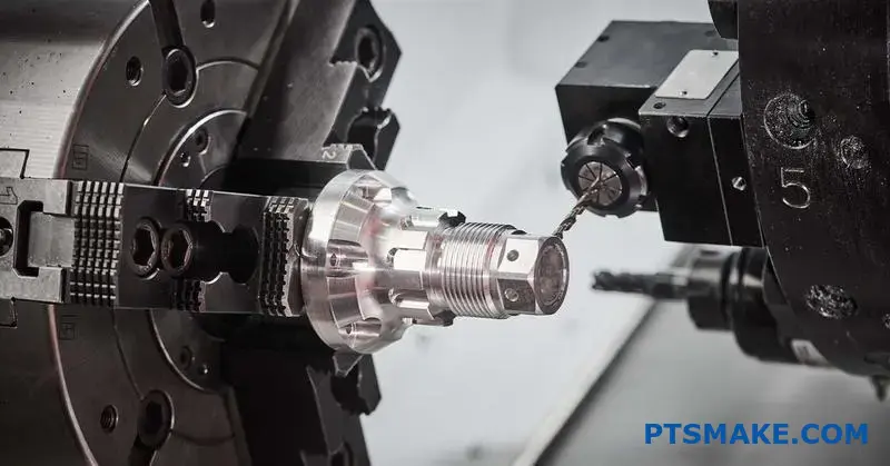
Poor heat sink design kills electronics faster than most engineers realize. You design a perfect circuit, source quality components, and then watch thermal failures destroy your product’s reliability because the heat sink can’t handle real-world conditions.
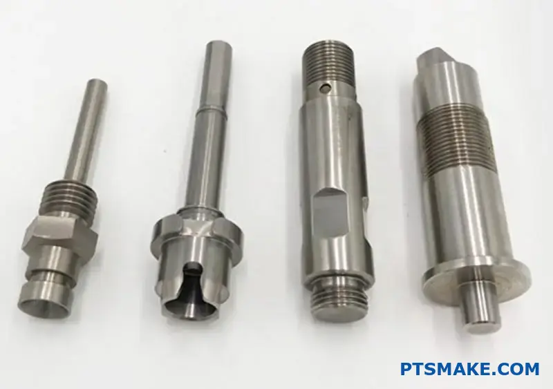
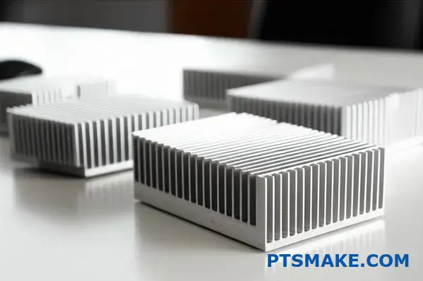
Stamped heat sinks offer a cost-effective thermal management solution that balances manufacturing efficiency with adequate cooling performance. These components use progressive die stamping to create fins directly from the base material, eliminating bonding interfaces while maintaining structural integrity for medium-power applications.
The choice between stamping, extrusion, or bonded fins often determines your project’s success. I’ve worked with engineering teams who struggled with this decision, watching prototypes fail thermal testing because they picked the wrong manufacturing approach. This guide walks you through the technical considerations that matter most when designing stamped heat sinks for your specific application.
What makes a heat sink design ‘stampable’?
Ever wonder what makes a heat sink design truly manufacturable? It’s not just about thermal performance. For a stamping heat sink, it all comes down to Design for Manufacturability (DFM).
DFM ensures your design is efficient and cost-effective to produce. It avoids costly rework and delays.
Core Stamping Principles
Key factors determine if a design is "stampable." These include material choice, thickness, and the geometry of features like fins. Ignoring these can lead to production failures.
Key Design Considerations
A successful design balances thermal needs with manufacturing limits.
| Parameter | Guideline for Stamping |
|---|---|
| Minimum Bend Radii | Generally, at least 1x material thickness |
| Fin Aspect Ratio | Keep height-to-thickness ratio low |
| Feature Placement | Allow ample space between features |
| Material Thickness | Must be consistent throughout the part |
Following these simple rules is the first step. It makes the entire production process smoother for everyone involved.
Designing for stamping is a game of respecting the material’s limits. It’s about understanding how sheet metal behaves under pressure. You can’t just create sharp, 90-degree bends without consequences.
Why Minimum Bend Radii Matter
When you bend metal, the outer surface stretches and the inner surface compresses. If the bend is too sharp for the material’s thickness, the outer surface can crack. This is a common failure point we see in unoptimized designs. As a rule of thumb, the inside bend radius should be at least equal to the material’s thickness.
Limitations on Material and Fins
The material thickness must be consistent. Stamping tools are designed for a specific thickness. Varying it isn’t feasible. The process involves controlled material deformation1, and consistency is key.
Also, consider the aspect ratio of fins. Very tall, thin fins are prone to bending or breaking during the stamping process. They can also cause issues with material flow in the die.
Avoiding Common Defects
Strategic feature placement is crucial. Placing holes, slots, or other features too close to a bend or the edge can cause tearing or distortion. The material needs space to flow and form correctly.
| Feature Placement | Minimum Distance from Bend | Minimum Distance from Edge |
|---|---|---|
| Holes (Round) | > 2.5x Material Thickness | > 1.5x Material Thickness |
| Slots (Rectangular) | > 3.0x Material Thickness | > 2.0x Material Thickness |
At PTSMAKE, we often review designs with our clients to catch these issues early. A small adjustment in the design phase saves significant time and cost later.
A ‘stampable’ heat sink follows DFM principles like minimum bend radii and smart feature placement. Respecting material thickness and fin aspect ratio is key. This approach prevents defects, ensuring efficient and cost-effective production from the start.
How does it differ from an extruded heat sink?
When choosing a heat sink, the manufacturing method is critical. Stamped and extruded heat sinks seem similar. But they differ greatly in cost and design.
At PTSMAKE, we guide clients through this choice daily. It often comes down to budget and production volume.
Cost and Production Volume
Your initial investment versus long-term cost is a key factor. A stamping heat sink requires a higher upfront tooling cost. But its piece price is much lower in mass production.
| Factor | Stamping Heat Sink | Extruded Heat Sink |
|---|---|---|
| Tooling Cost | High | Low |
| Piece Price | Very Low (High Volume) | Moderate |
| Best For | Mass Production | Prototypes, Low Volume |
This trade-off is fundamental. It shapes your entire project’s financial planning.
Thermal Performance and Design
Extruded heat sinks generally use aluminum alloys. These materials offer excellent, consistent thermal conductivity. This makes them a reliable, straightforward choice for many applications. They are solid performers.
However, a stamping heat sink offers more design freedom. You aren’t limited to a single cross-section. Stamping allows for complex, three-dimensional shapes.
The Flexibility Advantage
We can create fins with variable density and geometry. This optimizes airflow in tight spaces. This is impossible with extrusion. The metal also undergoes work hardening2 during stamping, which can slightly alter its characteristics.
Material and Customization
Extrusion works best with aluminum. Stamping, however, handles various materials. We often use copper for its superior thermal properties. This is a huge advantage for high-performance needs.
| Feature | Stamping Heat Sink | Extruded Heat Sink |
|---|---|---|
| Thermal Performance | Good to Excellent (Material Dependent) | Good to Excellent |
| Design Flexibility | High (Variable fin density) | Low (Fixed cross-section) |
| Material Options | Aluminum, Copper, etc. | Primarily Aluminum Alloys |
The best method depends on your specific goals. You must balance performance, cost, and design needs.
While extruded sinks offer solid, reliable performance, stamped heat sinks provide unique design flexibility. They also offer significant cost advantages in high-volume production, making the choice dependent on your project’s specific needs and scale.
What are the inherent thermal and mechanical limitations?
Every technology has boundaries. Understanding these is key for successful product design. For stamping heat sinks, the main limitations are thermal and mechanical.
We must consider the fin height-to-thickness ratio. Taller, thinner fins seem ideal. But they can bend during production. This impacts performance and reliability.
Fin Ratio Reality
There’s a trade-off between surface area and manufacturability. Pushing the limits too far leads to issues.
| Aspect | Ideal Goal | Practical Limit |
|---|---|---|
| Fin Height | Maximize for area | Limited by material stability |
| Fin Thickness | Minimize for weight | Must resist bending |
| Ratio | High | ~15:1 to 20:1 (Varies) |
Deeper Dive into Constraints
The connection between the fin and base is critical. It’s never a perfect thermal bond. There is always some level of interfacial thermal resistance3. This small gap, even microscopic, can impede heat flow. It reduces the heat sink’s overall efficiency. At PTSMAKE, we focus on minimizing this through precise process control.
Another major concern is structural integrity. How does the part behave under stress? Vibration is a common problem, especially in automotive or industrial applications. A poorly designed stamping heat sink can suffer from fatigue and fail prematurely. We analyze these dynamic loads carefully during the design phase.
Common Mechanical Failure Points
We need to anticipate potential weaknesses. Past project experience helps us identify these early.
| Stress Factor | Potential Failure Mode | Design Consideration |
|---|---|---|
| Vibration | Fin cracking at the base | Reinforcing base geometry |
| Mechanical Shock | Permanent deformation | Material selection, stiffeners |
| Constant Pressure | Material creep over time | Choosing alloys with high stability |
This focus on manufacturability ensures the final product meets both thermal and mechanical specifications reliably. It’s about balancing ideal performance with real-world physics.
The primary limitations of stamped heat sinks involve the fin geometry ratio, the imperfect thermal bond between components, and ensuring structural integrity under vibration and mechanical stress. These factors must be balanced for optimal, reliable performance.
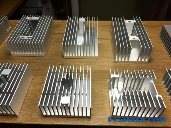
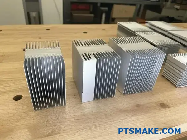
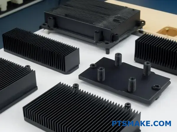
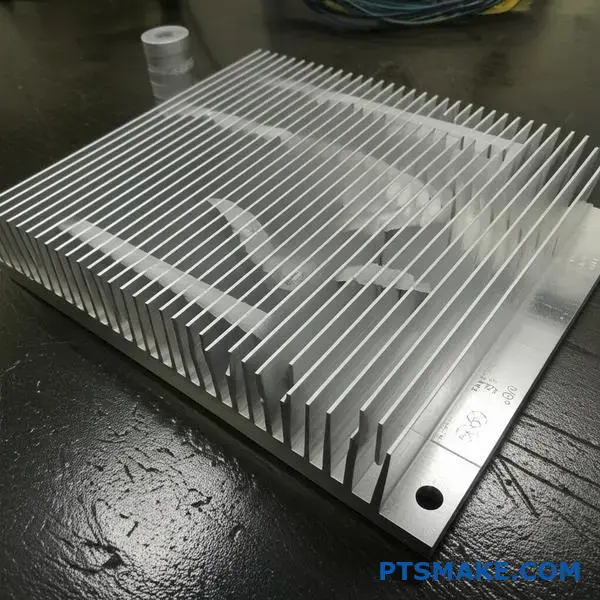
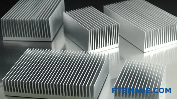
What are the main types of stamped fin geometries?
Stamped fins come in various geometries. Each design offers unique thermal and structural benefits. Understanding these helps in selecting the right solution for your needs.
Let’s explore two of the most common types.
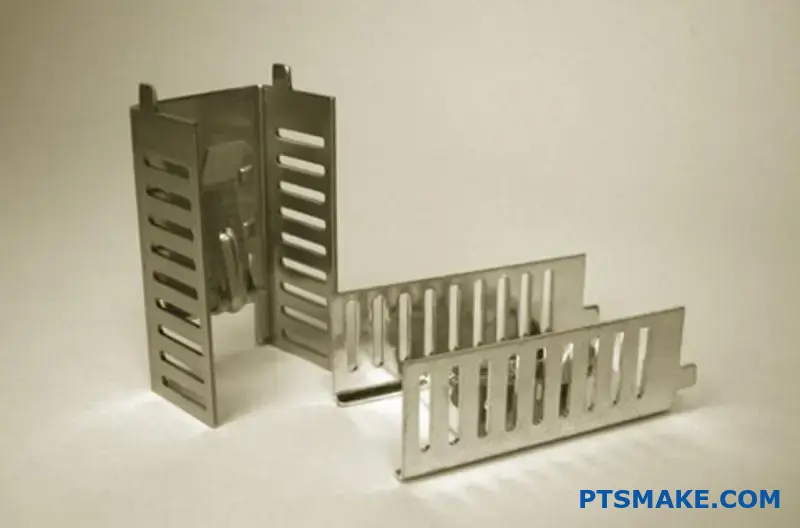
Zipper Fins
Zipper fins are stamped individually. They are then stacked and interlocked. This process forms a dense and robust fin array. It’s a popular choice for many applications.
Folded Fins
Folded fins are created from a single sheet. The metal is bent back and forth continuously. This creates a structure similar to an accordion.
| Fin Type | Manufacturing Method | Key Advantage |
|---|---|---|
| Zipper Fin | Individual stamping & stacking | High density & rigidity |
| Folded Fin | Continuous bending | Simpler assembly |
These designs are foundational to creating an effective stamping heat sink.
The choice between zipper and folded fins goes beyond looks. It impacts performance, cost, and assembly. Your specific application will guide the best decision.
Deeper Dive: Zipper Fin Applications
Zipper fins are excellent for high-power applications. Their interlocking design creates a very stable structure. This allows for dense fin packs, maximizing surface area.
They also integrate well with heat pipes. The fins can be stamped with precise cutouts. This ensures a tight fit and optimal thermal contact.
Manufacturing these fins often involves progressive die stamping4. While initial tooling can be an investment, it drives down unit costs in high-volume production.
Folded Fin Considerations
Folded fins shine in cost-sensitive projects. Their manufacturing process is simpler, using a single piece of material. This reduces assembly complexity and time.
A primary challenge is ensuring a solid thermal bond. The fin must make consistent contact with the heat spreader or base.
In past projects at PTSMAKE, we typically use brazing or thermal epoxy. This guarantees a secure bond and efficient heat transfer. The final design choice always depends on a balance of performance and budget.
Zipper and folded fins are two primary stamped fin types. Zipper fins offer high fin density and structural stability, ideal for complex designs. Folded fins provide a simpler, more cost-effective solution with straightforward assembly.
How are these heat sinks categorized by application?
Not all heat sinks are created equal. The application is the most important factor in its design. A heat sink for an LED light is very different from one for a server CPU.
Their jobs are the same: dissipate heat. But their environments and heat loads are worlds apart. This directly impacts their final form and function. Let’s compare them.
| Feature | Low-Power LED | High-Performance CPU |
|---|---|---|
| Cooling Method | Passive (Convection) | Active (Forced Air) |
| Fin Density | Low (Wide Pitch) | High (Dense Fins) |
| Cost Priority | High | Moderate |
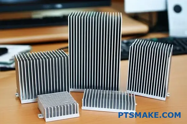
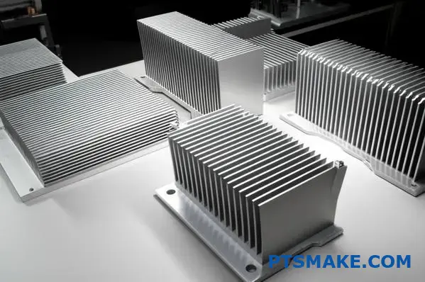
Let’s look at low-power LED lighting first. Here, the goal is simple and cost-effective cooling. These applications almost always use passive heat sinks.
The fins are spaced far apart. This design helps natural air convection work efficiently. It also stops dust from easily clogging the fins over many years of use. For these, a basic stamping heat sink or an aluminum extrusion is often the perfect solution. It gets the job done at a low cost.
Server CPUs are a completely different challenge. They produce a huge amount of heat in a very small space. This is where active cooling becomes essential.
A fan forces air across a dense array of thin fins. This design maximizes the surface area for heat exchange in a tight environment. The high heat flux5 from the processor demands this aggressive approach.
In our experience at PTSMAKE, manufacturing these high-density fins requires precision. We often use CNC machining to create the complex geometries and tight tolerances needed for these critical server components. This ensures optimal thermal transfer and reliability.
| Design Consideration | LED Lighting | Server CPU |
|---|---|---|
| Thermal Load | Low | Very High |
| Airflow | Natural Convection | Forced Convection (Fan) |
| Environment | Open Air / Household | Enclosed Server Rack |
| Reliability Need | Standard | Mission-Critical |
A heat sink’s design is tailored to its job. A simple, passive design works for low-power LEDs. But high-performance CPUs need complex, active cooling solutions to manage intense heat loads and ensure reliability. Application always defines form and function.
What design features facilitate mounting and integration?
Proper mounting is key for any component. For a stamping heat sink, it’s about both stability and thermal performance. The right features make installation simple and secure.
This ensures a tight fit onto the PCB. A good connection maximizes heat transfer away from your critical components.
Key Mounting Solutions
We focus on integrated mounting features. These are built directly into the heat sink during manufacturing. This approach reduces assembly time and potential failure points.
Installation Simplicity
Choosing the right feature depends on your assembly process and budget. Each offers unique benefits for different applications.
| Feature Type | Best For | Installation Speed |
|---|---|---|
| Stamped Holes | Cost-sensitive projects | Moderate |
| Threaded Inserts | High-vibration environments | Slower |
| Push-Pins | Quick, tool-less assembly | Very Fast |
Good design is more than just cooling fins. It’s about how the part fits into the larger system. Seamless integration saves time and prevents headaches during final assembly. This is something we prioritize at PTSMAKE from the initial design review.
A Deeper Look at Integration Features
Let’s break down the most common mounting options. Each one solves a specific engineering challenge. The choice impacts assembly efficiency and overall product reliability.
Stamped Mounting Holes
These are the simplest and most cost-effective solution. The holes are created during the stamping process itself. This means no secondary operations are needed. It’s ideal for high-volume production where every second and cent matters.
Threaded Inserts (PEMs)
For applications requiring strong, reusable connections, threaded inserts are perfect. These are small fasteners installed into the heat sink using a clinching process6. They provide robust threads for screws, which is crucial in devices that experience vibration or require frequent servicing.
Push-Pin Locations
Push-pins offer a fast, tool-free installation method. The heat sink is designed with specific holes that align with plastic or metal push-pins. This method allows for quick mounting and removal, making it great for prototypes and easy-access enclosures.
| Mounting Method | Primary Benefit | Common Use Case |
|---|---|---|
| Stamped Holes | Low Cost | Consumer Electronics |
| Threaded Inserts | High Security | Automotive & Industrial |
| Push-Pins | Fast Assembly | PC Components & Servers |
Smart design features like stamped holes, threaded inserts, and push-pin locations are essential. They ensure that a stamping heat sink can be installed easily, reliably, and cost-effectively, directly impacting assembly speed and product durability.
How do you design a stamping heat sink from requirements?
A structured workflow is key. It turns requirements into a functional stamping heat sink. This process prevents costly errors and delays. We follow a clear, five-step path.
It ensures every design decision is logical and data-driven. This approach builds success from the start.
The Design Workflow
Here’s a breakdown of the process:
| Step | Action |
|---|---|
| 1 | Define Thermal Budget |
| 2 | Select Material & Construction |
| 3 | Perform Simulation |
| 4 | Create CAD Model (with DFM) |
| 5 | Iterate and Refine |
This systematic approach is essential.
Designing a stamping heat sink is more than just bending metal. It’s a calculated engineering process. Let’s explore these steps in greater detail.
1. Defining the Thermal Budget
First, you must establish the thermal budget7. This includes the maximum allowable component temperature and the total power it dissipates. This non-negotiable foundation dictates all subsequent design choices for the heat sink.
2. Material and Construction
Next, select your material. Aluminum alloys like 1050 or 6061 are common. Copper offers better conductivity but costs more. Your choice depends on the budget and performance needs. The basic construction, like fin density and shape, is also decided here.
3. Simulation is Crucial
We then move to simulation. Simple analytical models provide quick estimates. However, for complex airflow, CFD (Computational Fluid Dynamics) simulation is invaluable. It predicts performance with high accuracy before any metal is cut.
| Simulation Type | Best Use Case |
|---|---|
| Analytical | Quick, early-stage estimates |
| CFD | Complex airflow, high accuracy |
4. CAD with DFM in Mind
With a simulated design, we create the CAD model. At PTSMAKE, we embed Design for Manufacturability (DFM) rules from the very beginning. This ensures the part can be stamped efficiently, saving time and money later.
5. Iteration for Perfection
Finally, iterate. The first design is rarely the last. We use simulation results and DFM feedback to refine the CAD model. This cycle continues until the design meets all thermal, mechanical, and cost requirements.
A structured design workflow, from defining thermal limits to iterative refinement, is critical. This systematic process ensures the final stamping heat sink is not only effective but also manufacturable and cost-efficient, preventing unforeseen issues during production.
When should you move from stamping to another technology?
Stamped heat sinks are incredibly efficient. But they have clear limitations. Knowing when to switch is key to project success. This decision point is the crossover point.
It’s where thermal demands or geometric complexity exceed what stamping can offer. Higher heat loads or intricate designs often require a different approach. Let’s explore when to make that move.
Key Crossover Triggers
| Trigger | Stamping Suitability | Alternative Needed |
|---|---|---|
| Heat Flux | Low to Medium | High to Very High |
| Complexity | Simple Geometries | Complex Shapes |
| Fin Density | Low | High |
Moving Beyond Stamping: Advanced Solutions
When a standard stamping heat sink can’t keep up, it’s time to consider more advanced options. Each technology solves a specific thermal challenge.
Bonded Fin Heat Sinks
Bonded fins offer design flexibility. You can combine materials, like a copper base for conductivity and aluminum fins for weight savings. This is ideal for very large heat sinks or high-power applications.
Skived Fin Technology
For compact devices needing maximum cooling, skived fins are a great choice. A single block of metal is "skived" to create very thin, dense fins. This creates a huge surface area in a small footprint.
Two-Phase Cooling
When dealing with intense, localized heat from a small source, two-phase cooling is the answer. Solutions like vapor chambers use a liquid-to-vapor phase change to rapidly move thermal energy away from the source. This process, known as isothermalization8, is extremely effective at managing hot spots.
Technology Selection Guide
| Technology | Best For | Key Advantage |
|---|---|---|
| Bonded Fin | High Power / Large Size | Material combinations, scalability |
| Skived Fin | High Fin Density | Maximum surface area in small space |
| Vapor Chamber | Concentrated Heat Source | Superior heat spreading |
Recognizing the crossover points is crucial. When thermal loads or complexity surpass stamping’s capabilities, alternatives like bonded fins, skived fins, or vapor chambers are necessary. Each offers a unique solution for advanced thermal management challenges.
Unlock Advanced Stamped Heat Sink Solutions with PTSMAKE
Ready to take your stamping heat sink project to the next level? Contact PTSMAKE today for a fast, detailed quotation and discover how our expertise in precision manufacturing can deliver superior performance and quality for your application. Your custom solution starts with a single inquiry—reach out now!

Discover the core mechanics of how metal reshapes during the stamping process. ↩
Learn how mechanical stress alters material properties and impacts component performance. ↩
Learn how this property impacts heat transfer and overall performance in your designs. ↩
Understand how this multi-stage stamping process can improve efficiency and cut costs for high-volume production. ↩
Learn how this key metric influences thermal management and material choices for your project. ↩
Understand this cold-forming method for joining sheet metal without using heat or fasteners. ↩
Click to understand how defining a thermal budget is the crucial first step for successful heat sink design. ↩
Understand the physics of two-phase cooling and how it achieves rapid, uniform temperature distribution. ↩