Need help choosing the right Branson ultrasonic welder for your application? Many engineers struggle with understanding the complex variations in models, components, and configurations available in Branson’s extensive product line, leading to suboptimal equipment selection and weld process development challenges.
Branson offers multiple welder series including the 2000X, IW+, and GSX lines, each featuring different control systems, actuator types, and data capabilities designed for specific manufacturing requirements from basic welding to advanced process monitoring and automation integration.
This guide breaks down every component and process parameter you need to master Branson welders. I’ll walk you through the technical specifications, setup procedures, and troubleshooting methods that will help you optimize your ultrasonic welding operations and avoid common application mistakes.
What are the primary Branson welder model series?
Choosing the right Branson welder is crucial. Your choice impacts assembly quality and efficiency. The main series each serve different needs.
Key Branson Welder Families
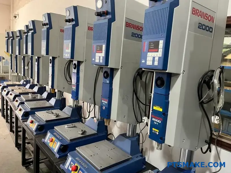
Branson offers several distinct model lines. The most common are the 2000X, IW+, and the advanced GSX series. Each has a specific purpose.
Quick Comparison Overview
Understanding their core differences is the first step. This helps narrow down the best fit for your production line.
| Model Series | Primary Control System | Target Application |
|---|---|---|
| 2000X | Time/Energy/Distance | General Purpose, High-Volume |
| IW+ | Time/Energy | Basic, Integrated Systems |
| GSX | Advanced, Ethernet-based | High-Tech, Data-Intensive |
This table provides a high-level view. Let’s explore what these differences mean for manufacturing.
Diving deeper, the technology behind each series dictates its capabilities. At PTSMAKE, we select equipment based on the specific precision requirements of a project, whether for injection molding or post-processing assembly.
Control Systems and Data Capabilities
The control system is the brain of the welder. The 2000X series offers robust control over weld time, energy, and distance. This makes it a versatile workhorse for many applications.
The IW+ series is more streamlined. It focuses on time and energy modes, ideal for integration into automated systems where simplicity and reliability are key.
The GSX platform is the most advanced. It uses an Ethernet-based system for precise control and extensive data logging. This is critical for medical or automotive parts where full traceability is required. A precise actuator1 works with this system for unmatched accuracy.
Actuator Types and Applications
The mechanical unit, or actuator, also varies. The 2000X series uses various actuator types, balancing force and rigidity for consistent results. This flexibility is why it’s a popular branson ultrasonic welder.
The GSX series introduces electromechanical actuators. Our tests show these provide superior precision over traditional pneumatic ones, allowing for finer control of weld collapse distance and force.
| Feature | 2000X Series | GSX Series |
|---|---|---|
| Actuator Type | Pneumatic (Various Models) | Electromechanical |
| Data Logging | Standard, with options | Advanced, IIoT-ready |
| Weld Modes | Time, Energy, Distance | Multiple advanced modes |
| Best For | High-volume manufacturing | Precision, regulated industries |
This detailed comparison helps align a welder’s capabilities with specific production demands.
Branson welder models like the 2000X, IW+, and GSX series offer distinct control systems and actuator technologies. Your choice depends on the application’s need for precision, data traceability, and integration, directly impacting your manufacturing success.
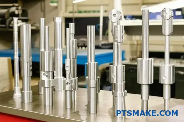
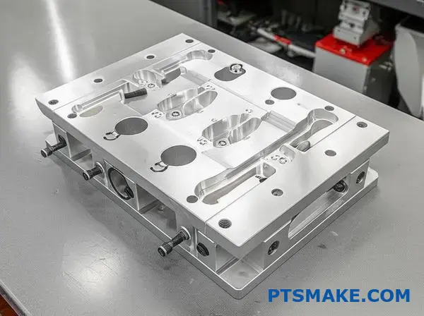
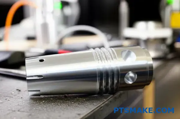
How are Branson horns classified by material and design?
Selecting the right horn is crucial. It’s about matching the tool to the task. The classification breaks down into two key areas: the material it’s made from and its physical shape. Each choice directly impacts performance.
Material Selection: The Foundation of Performance
The horn’s material determines its durability, acoustic properties, and cost. It’s the first decision point. You must balance wear resistance with acoustic efficiency. There is no single best material; it’s about the right fit.
| Material | Key Characteristics | Common Applications |
|---|---|---|
| Titanium | Excellent acoustics, high fatigue strength | High-stress, continuous-duty welding |
| Aluminum | Good acoustics, lower cost, lightweight | Prototyping, low-volume applications |
| Steel | High wear resistance, hardened tips | Inserting, staking, metal welding |
Horn Design: Shaping the Energy
The horn’s geometry, or shape, focuses and amplifies the ultrasonic energy. Different shapes provide different levels of gain (amplification). This choice depends on the weld requirements and the part design itself.
The interplay between material and design is where the real engineering happens. It’s not enough to just pick a strong material. You need to consider how that material behaves when shaped into a specific geometry that must resonate at a precise frequency.
Deeper Dive into Design Implications
For instance, a titanium horn is superior for high-amplitude applications not just for its strength, but also its low internal energy loss. Aluminum is great for prototypes because it’s easy to machine at PTSMAKE, allowing for quick design iterations. However, it wears faster.
The choice of shape directly controls the amplitude gain. This is the ratio of the output amplitude at the horn’s face to the input amplitude from the converter. A stepped horn offers high gain but also creates high stress at the transition point. In contrast, a catenoidal horn provides moderate gain with more evenly distributed stress. Understanding Acoustic Impedance2 is key to optimizing energy transfer between the horn and the workpiece. A mismatch here can lead to poor welds and horn damage.
Common Horn Shapes and Their Gain
Here’s how different designs for a Branson ultrasonic welder typically perform. In our tests, we’ve seen how a simple shape change can dramatically alter weld results.
| Horn Shape | Amplitude Gain | Stress Profile | Best For |
|---|---|---|---|
| Stepped | High | High, concentrated | High-intensity spot welding, small parts |
| Catenoidal | Moderate | Uniformly distributed | Delicate components, reducing stress |
| Exponential | Moderate | Gradual transition | General purpose, good balance |
| Bar/Rectangular | Low | Varies | Large, flat parts; multiple weld points |
Choosing the right Branson horn is a critical step. It involves balancing the acoustic properties and wear resistance of materials with the specific amplification and stress distribution provided by different geometric designs to achieve optimal welding results.
What are the different types of weld modes available?
When using an advanced machine like a Branson ultrasonic welder, you have several control modes. Think of these as different recipes for creating the perfect weld.
Each mode controls the welding cycle using a different primary variable. Choosing the right one is critical. It ensures consistency and quality in the final product.
Key Welding Control Modes
| Mode | Primary Control | Best For |
|---|---|---|
| Time | Weld Duration | Simple, consistent parts |
| Energy | Energy Delivered | Parts with slight variations |
| Distance | Part Collapse | Precise final dimensions |
This choice directly impacts the strength and appearance of every weld we produce.

Understanding these modes is key to mastering ultrasonic welding. Let’s break down the most common options you’ll find and when to use them.
Time Mode
This is the most basic mode. The welder applies ultrasonic vibrations for a pre-set amount of time. It’s straightforward and works well for simple applications where parts are very consistent. However, it can’t compensate for material or dimensional variations.
Energy Mode
In this mode, the welder delivers a precise amount of energy to the parts. It measures the energy used in real-time and stops once the target is met. At PTSMAKE, we often use this for materials with slight surface or density variations. It provides more consistent results than time mode in these cases.
Distance Modes: Collapse and Absolute
These modes control the weld based on physical part dimensions.
- Collapse Distance: The weld stops after the part has melted and compressed by a specific amount.
- Absolute Distance: The weld stops when the part reaches a specific final height. This is crucial for applications requiring tight assembly tolerances. The material’s viscoelasticity3 is a key factor in how it behaves under this precise control.
Peak Power Mode
Here, the weld cycle ends when the power drawn by the acoustic stack reaches a specific peak value. This is useful for delicate components. It helps prevent over-welding or damage to sensitive internal parts.
| Mode | Ideal Use Case | Key Benefit |
|---|---|---|
| Time | High-volume, identical parts | Simplicity, speed |
| Energy | Parts with material variability | Consistent melt |
| Peak Power | Delicate or thin-walled parts | Prevents part damage |
| Collapse Dist. | When melt volume is critical | Repeatable weld depth |
| Absolute Dist. | Assemblies with tight tolerances | Precise final height |
Each mode offers a unique way to control the welding process. Selecting the correct mode is fundamental to achieving a robust and reliable weld tailored to the specific part design and material. This ensures every product meets our high-quality standards.
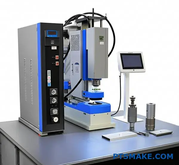
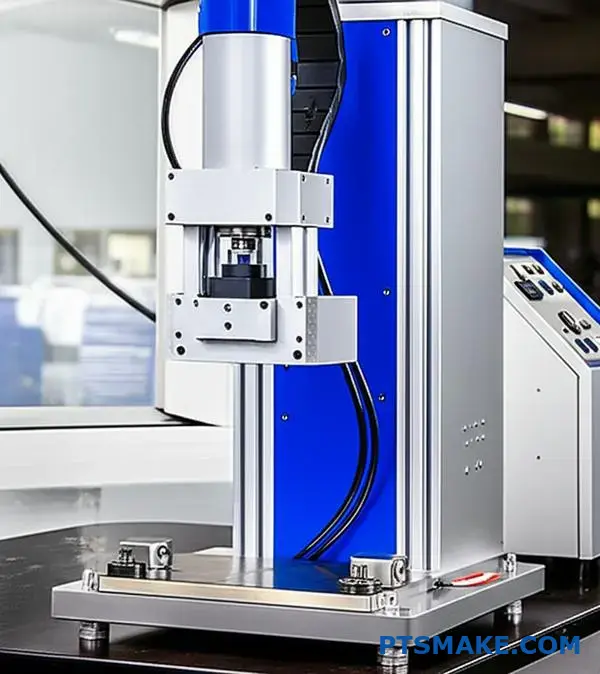
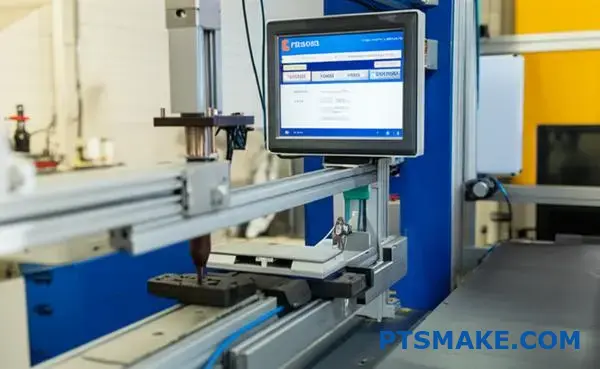
What is the system architecture of a modern Branson welder?
A modern Branson welder is a finely tuned system. It consists of four critical subsystems working in concert. Each part has a distinct role.
They communicate constantly to deliver precise results. This integration is key to achieving a perfect weld.
Key Subsystems Overview
| Subsystem | Primary Function |
|---|---|
| Power Supply Unit | Generates high-frequency electrical energy. |
| Actuator/Press | Applies precise force to the parts being joined. |
| Acoustic Stack | Converts electrical energy into mechanical vibration. |
| User Interface/Controller | Manages and monitors the entire weld process. |
This modular architecture ensures precision and repeatability. These are qualities we demand for every project at PTSMAKE.
The Weld Cycle: A Symphony of Interaction
The welding process is a carefully choreographed sequence. It all begins at the user interface. Here, an operator inputs the required weld parameters. These include time, pressure, and energy levels.
The controller acts as the system’s brain. It takes these settings and starts the cycle. It first commands the actuator to apply a precise downforce. This action brings the parts into firm contact.
Simultaneously, the controller triggers the power supply. The power supply then sends a high-frequency electrical signal to the acoustic stack. Within the stack, a transducer4 converts this electrical signal into high-frequency mechanical vibrations.
These powerful vibrations create intense friction at the part interface. This generates heat, causing the plastic to melt and fuse. Throughout this brief process, sensors feed real-time data back to the controller. This allows for instant adjustments to maintain consistent weld quality. This level of control is essential.
A Typical Weld Cycle Interaction
| Step | Action | Communicating Subsystems |
|---|---|---|
| 1. Part Clamping | Actuator applies force to hold parts. | Controller -> Actuator |
| 2. Ultrasonic Trigger | Power supply is activated to create vibrations. | Controller -> Power Supply -> Acoustic Stack |
| 3. Weld Phase | Vibrations create a molten bond. | Acoustic Stack <-> Controller (Feedback) |
| 4. Hold Phase | Pressure is maintained as parts cool. | Controller -> Actuator |
| 5. Retraction | Actuator retracts, releasing the finished part. | Controller -> Actuator |
This closed-loop communication makes the Branson ultrasonic welder exceptionally reliable for complex assemblies.
A Branson welder’s architecture is a system of four core units. The controller orchestrates the power supply, actuator, and acoustic stack. They communicate seamlessly through the weld cycle, ensuring a strong, repeatable bond for every single component.
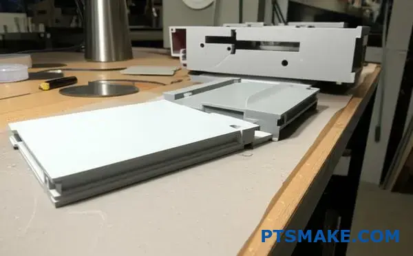
What are the main categories of ultrasonic joint design?
Choosing the right joint design is critical. It dictates how ultrasonic energy is focused. It also helps contain the molten plastic. Three common designs dominate most applications.
Key Joint Design Types
We often work with the Shear Joint, Step Joint, and Tongue-and-Groove Joint. Each has unique strengths. They solve different engineering challenges.
| Joint Design | Primary Advantage | Common Use Case |
|---|---|---|
| Shear Joint | Maximum Strength & Sealing | Hermetic enclosures |
| Step Joint | Self-Aligning | Housings & Covers |
| Tongue-and-Groove | Precise Alignment & Clean Look | Aesthetically critical parts |
These designs are foundational for successful welds.
A Closer Look at Each Design
The specific geometry of a joint design directly impacts weld quality. Understanding their differences is key to selecting the best option for your part. At PTSMAKE, we guide clients through this selection process daily.
The Shear Joint
This design creates a strong, leak-proof weld. It’s ideal for parts that need to withstand pressure or keep elements out. The vertical walls smear together during welding. This process creates a very reliable bond. It’s often used for sealed containers and medical devices, where a hermetic seal5 is absolutely necessary.
The Step Joint
The step joint is excellent for self-alignment. This feature simplifies the assembly process. It is particularly useful for large parts or parts with flexible walls. This design helps prevent misalignment during the welding cycle. You see it often in electronic enclosures and consumer product casings.
The Tongue-and-Groove Joint
For superior alignment and aesthetics, this is the best choice. The tongue-and-groove design provides a precise fit. It also effectively traps flash internally. This keeps the exterior surface clean. It’s perfect for parts where appearance is paramount. We often recommend it for high-end consumer electronics. A capable machine, like a Branson ultrasonic welder, ensures these intricate features are welded perfectly.
| Joint Type | Ideal For | Industry Example |
|---|---|---|
| Shear | Sealing & Strength | Automotive Sensors |
| Step | Alignment | Appliance Housings |
| Tongue-and-Groove | Aesthetics & Precision | Premium Electronics |
Choosing the right joint design is a crucial step in part design and manufacturing. It ensures both functional performance and visual appeal.
Each joint has a distinct purpose. Shear joints are for strength and sealing. Step joints aid in alignment. Tongue-and-groove joints offer precision and a clean finish. The best choice always depends on the specific requirements of your application.
How do different boosters (gain ratios) function?
Boosters are classified by their gain ratio. This ratio shows how they modify vibration amplitude. Common ratios include 1:1.5 and 1:2.0.
This number is a simple multiplier. A 1:1.5 ratio increases the amplitude by 50%. A 1:2.0 ratio doubles it. This adjustment happens before the amplitude reaches the horn.
Selecting the correct booster is a key step in setting up a reliable welding process.
| Booster Ratio | Amplitude Change |
|---|---|
| 1:1.0 | No Change |
| 1:1.5 | +50% Increase |
| 1:2.0 | +100% Increase |
| 1:2.5 | +150% Increase |
A booster is a tuned mechanical component. It works by changing its cross-sectional area. This change modifies the amplitude of the ultrasonic waves passing through it.
The booster is mounted to the press at its center, which is the nodal point6. At this specific point, there is almost no back-and-forth motion. This ensures all energy is transferred forward efficiently.
In past projects at PTSMAKE, choosing the right booster was critical. For a medical device with delicate internal electronics, we used a lower-gain booster to prevent damage. This provided just enough energy for a strong, clean weld.
For more robust applications, a higher-gain booster delivers more power. This ensures faster cycle times and a stronger bond. Using the correct booster on a system, such as a Branson ultrasonic welder, is essential for process control and repeatability. The right choice depends entirely on the material and part geometry.
| Gain Ratio | Typical Application | Material Suitability |
|---|---|---|
| Low Gain (e.g., 1:1.5) | Delicate parts, shear joints | Amorphous plastics (e.g., ABS, PC) |
| High Gain (e.g., 1:2.0) | Strong welds, staking/inserting | Crystalline plastics (e.g., Nylon, PP) |
Boosters are classified by gain ratios that multiply the converter’s amplitude. They are mounted at a nodal point to ensure stable energy transfer. Selecting the correct booster is crucial for matching the welding process to the specific material and application requirements.
What are the different types of fixtures (anvils)?
Fixtures, or anvils, are the foundation of a good weld. Their material and design are not small details. They are critical for success.
The choice directly impacts part support and weld quality. We must consider every aspect carefully.
Fixture Materials
Selecting the right material is the first step. Each has unique properties suited for different applications.
| Material | Key Benefit | Best For |
|---|---|---|
| Steel | High rigidity & durability | High-volume production, abrasive plastics |
| Aluminum | Good thermal conductivity | Heat-sensitive parts, rapid prototyping |
| Polymer | Prevents part marking | Delicate or Class-A surfaces |
Fixture Designs
The design dictates how the part is held. This ensures energy is focused only on the weld joint. The two most common designs are contoured nests and clamping mechanisms.
A poorly designed fixture can ruin an entire production run. The goal is to support the part rigidly without causing cosmetic damage. This is especially true for ultrasonic welding.
The high-frequency vibrations from a tool like a Branson ultrasonic welder demand an extremely stable base. Any movement in the part will absorb energy. This leads to weak or incomplete welds.
At PTSMAKE, we often design fixtures with a combination of features. We might use a hard-coated aluminum nest for durability. Then, we add small polymer inserts at key contact points. This protects the part’s surface.
This hybrid approach balances rigidity and part protection. It ensures consistent results. The fixture’s design must perfectly mirror the part’s geometry. This is non-negotiable for achieving a strong, reliable weld. We must also consider how the fixture affects the part’s Durometer7 and overall integrity post-weld.
A fixture’s design must account for:
| Design Factor | Importance |
|---|---|
| Part Support | Prevents flexing and energy loss. |
| Alignment | Ensures the horn contacts the part precisely. |
| Clamping Force | Secures the part without distortion. |
| Ergonomics | Allows for easy loading and unloading. |
Choosing the right material and design for your fixture is crucial. These decisions directly support the part, prevent damage, and ensure a high-quality, repeatable weld. A well-made anvil is an investment in consistency.
How do Branson’s actuator control systems differ?
Choosing the right actuator is key for ultrasonic welding. It’s the muscle behind the process. Branson offers two main types: pneumatic and electro-mechanical. Each system controls force and motion differently.
This choice directly impacts weld consistency. It determines how well you can control the entire process. For any branson ultrasonic welder, understanding this is crucial. It defines the machine’s capability.
A simple breakdown helps clarify the main differences.
| Feature | Pneumatic System | Electro-Mechanical System |
|---|---|---|
| Power Source | Compressed Air | Electric Motor |
| Control Level | Basic | High-Precision |
| Repeatability | Good | Excellent |
| Best For | Simpler applications | Complex, critical welds |
This decision affects not just the weld, but your production efficiency.
Pneumatic Actuators: The Traditional Approach
Pneumatic systems are the classic choice. They use compressed air to apply force. They are reliable, robust, and cost-effective for many applications. I’ve seen them used successfully in countless straightforward projects at PTSMAKE.
However, their control is less precise. Air is compressible, so achieving dynamic force changes during the weld cycle is difficult. This can sometimes lead to slight inconsistencies, especially with complex parts or sensitive materials.
Electro-Mechanical Actuators: Precision and Control
Electro-mechanical systems represent a major step forward. They use a servomotor8 to drive the actuator. This allows for incredibly precise, digital control over every aspect of the weld: force, distance, and velocity.
This is where features like dynamic force control really shine. The system can apply a specific force profile throughout the weld cycle. It adjusts in real-time based on feedback from the part.
Impact on Process Consistency
This advanced control has a huge impact. It ensures every single weld is performed with the exact same parameters. This eliminates variability and improves part quality dramatically. In our experience, this is essential for medical and automotive components.
The table below gives a more detailed view.
| Control Parameter | Pneumatic Actuator | Electro-Mechanical Actuator |
|---|---|---|
| Force Control | Static, less responsive | Dynamic, real-time profiling |
| Velocity Control | Limited | Fully programmable |
| Position Accuracy | Lower | Extremely high |
| Data Feedback | Basic | Comprehensive, for SPC |
This level of control ensures a highly capable and repeatable process.
In short, pneumatic actuators are reliable for standard jobs. Electro-mechanical systems, however, offer superior precision and dynamic control. This makes them essential for high-stakes applications where consistency is non-negotiable. Your application dictates the best choice.
What types of process data can Branson welders output?
Branson welders provide more than just a strong bond. They offer a detailed stream of data for every single weld.
This information is the backbone of modern quality control. It allows us to monitor the process in real-time.
By tracking these numbers, we can spot deviations instantly. This ensures that every part we produce at PTSMAKE meets the highest standards. It is a critical step in our quality assurance process.
Here’s a look at the essential data points you can get.
| Data Point | Importance in Quality Control |
|---|---|
| Weld Time | Indicates process consistency |
| Energy Used | Confirms sufficient material melt |
| Collapse Distance | Verifies proper part joining |
| Peak Power | Shows resistance and coupling |
| End Frequency | Monitors acoustic stack health |

Let’s break down why each piece of data is so valuable. Think of these data points as the vital signs of the welding process. Each one tells a unique part of the story.
The Value Behind the Numbers
A modern Branson ultrasonic welder doesn’t just weld; it analyzes. For every cycle, it records a detailed profile, creating a unique weld signature9 for a good part. This allows for incredibly precise process control.
Weld Time and Energy Used
These two metrics are fundamental. If the weld time or energy suddenly changes, it could point to variations in the raw material. It might also signal an issue with how the part is seated in the fixture. Consistent values mean a stable process.
Final Collapse Distance and Peak Power
Final collapse distance measures how much the parts compressed during the weld. This directly confirms that the right amount of material melted and flowed to create a strong joint. Peak power shows how much energy the joint required to form. Any significant change is an immediate red flag for our team.
End Frequency
End frequency is a more subtle but equally important metric. In our experience, a shift in frequency can indicate a change in the part’s geometry or even a problem with the welding tool itself. By monitoring it, we maintain the integrity of the entire welding system.
At PTSMAKE, we use this complete data set to set up strict pass/fail criteria. Any part welded outside these predefined limits is automatically flagged.
Monitoring these data points from a Branson welder is not just about collecting numbers. It is about using actionable intelligence to guarantee part consistency and quality, preventing potential failures before they ever leave our facility.
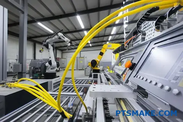
How are Branson welders integrated into automation systems?
Connecting a welder to an automation system is all about communication. It’s like teaching two machines to speak the same language. This ensures they work together seamlessly and safely.
The central controller, or PLC, needs to give commands and receive data. This connection makes the entire process efficient.
Key Communication Protocols
Modern systems use industrial Ethernet protocols. These are fast and reliable. They allow for complex data exchange beyond simple on/off signals. This is crucial for a branson ultrasonic welder.
| Protocol | Primary Use Case | Key Advantage |
|---|---|---|
| Ethernet/IP | Common in North America | Strong support from major automation suppliers. |
| Profinet | Widely used in Europe | High-speed performance for demanding tasks. |
This direct link is the brain of the automated cell.
Beyond high-level protocols, Input/Output (I/O) signals are fundamental. These are the basic digital "handshakes" between the welder and the PLC. They handle the most critical, time-sensitive tasks.
The Role of I/O Signals
I/O signals manage the core functions. They tell the welder when to start and stop a cycle. They also confirm if a part is present and correctly positioned. Think of them as the system’s reflexes.
At PTSMAKE, we map these signals carefully. A mistake here can cause production to halt. Precise signaling is key to reliable manufacturing.
| Signal Type | Function | Example |
|---|---|---|
| Input to PLC | Reports welder status | "Weld Cycle Complete," "Alarm Active" |
| Output from PLC | Commands the welder | "Start Weld Cycle," "Reset Alarm" |
Ensuring Safety and Control
Safety is the top priority. We use dedicated signals for safety interlocking10. This prevents the machine from operating if a safety gate is open. Or if an emergency stop is pressed.
Data collection is another vital aspect. The PLC can log weld parameters for every part. This data is essential for quality control and process validation. It helps us ensure every single part meets strict specifications.
Proper integration relies on clear communication protocols and precise I/O signaling. This connection between the PLC and the welder is the foundation for a reliable, safe, and data-rich automated process, turning individual machines into a cohesive system.
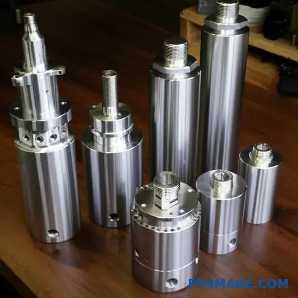
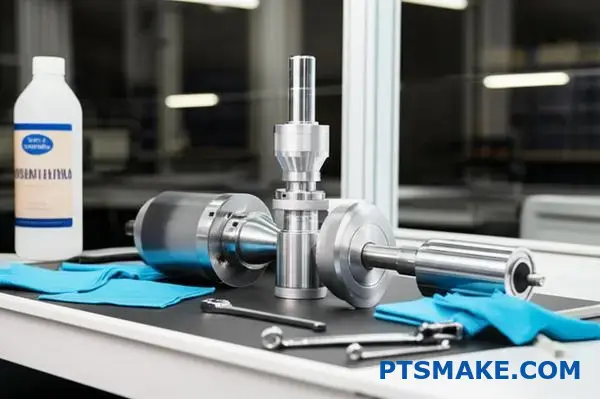
How do you correctly assemble and torque an acoustic stack?
Proper assembly is crucial. It ensures your ultrasonic welder performs correctly and lasts longer.
Think of it as a three-step process. Each step is as important as the last. Skipping one can lead to poor welds or damage.
Step 1: Clean the Surfaces
First, ensure all mating surfaces are perfectly clean. Any debris can disrupt energy transmission.
Step 2: Assemble Components
Next, carefully thread the components together by hand. They should turn smoothly without resistance.
Step 3: Apply Correct Torque
Finally, use a spanner wrench and torque wrench to apply the specified torque. This ensures a solid connection.
| Tool Required | Purpose |
|---|---|
| Lint-free cloths | Cleaning surfaces without leaving residue |
| Isopropyl alcohol | Degreasing and cleaning agent |
| Spanner wrench | To grip the horn or booster |
| Calibrated torque wrench | To apply precise tightening force |
The Importance of Meticulous Cleaning
We can’t stress this enough. Even a tiny particle of dust or oil can cause major problems. These contaminants can create hot spots.
This can lead to inconsistent welding performance. In the worst cases, it causes damage to the expensive stack components. This is especially true for high-frequency systems.
Contaminants can also lead to a type of wear called fretting corrosion11, which degrades the surfaces over time. It’s a silent killer of acoustic stacks.
Why Correct Torque is Everything
Applying the right torque creates the correct clamping force, or preload. This ensures the entire stack vibrates as a single, efficient unit. It’s vital for any model, including a Branson ultrasonic welder.
Without proper torque, the joints can have microscopic gaps. These gaps disrupt the flow of ultrasonic energy. They can cause heat buildup and lead to component failure. Over-torquing can also damage the threads.
| Common Issue | Likely Assembly Cause |
|---|---|
| Inconsistent weld quality | Improper torque or dirty surfaces |
| Overheating at joints | Loose connection (low torque) |
| Cracked components | Excessive torque |
| Damaged threads | Cross-threading or over-torquing |
At PTSMAKE, we always follow the manufacturer’s torque specifications precisely. It’s a non-negotiable step in our process.
A clean, carefully assembled, and correctly torqued acoustic stack is fundamental. It ensures optimal energy transmission, consistent performance, and protects your investment from premature failure. This procedure is key to reliable ultrasonic welding.
How do you establish baseline parameters for a new application?
Establishing the right parameters is not guesswork. It’s a systematic process. For any new application, we begin with a conservative approach. This protects the parts and the tooling.
Start Low and Go Slow
The core principle is simple. We start with low amplitude and low weld pressure. This creates a safe baseline. From here, we can make careful, incremental changes. This methodical approach prevents damage from overpowering the material initially.
Observing the Results
With each adjustment, we closely inspect the part. We look for initial signs of melting and bonding. The goal is to find the minimum energy needed for a good weld.
Here’s our typical starting point:
| Parameter | Starting Setting |
|---|---|
| Amplitude | Low (e.g., 20-30 microns) |
| Weld Pressure | Low (e.g., 1-2 bar) |
This careful process helps us define a preliminary "starting window" for production.
A Systematic Path to the Process Window
A successful ultrasonic weld depends on a repeatable process. That process starts with finding the ideal parameters. At PTSMAKE, we treat this as a scientific method. We don’t rush to a solution. We build to it one step at a time.
This ensures the final parameters are robust. They account for minor material or environmental variations. It is a foundational step for consistent quality in mass production.
The Iterative Adjustment Cycle
We follow a strict cycle: adjust, weld, and inspect. By changing only one variable at a time, we can clearly see its effect. This helps isolate the impact of amplitude versus pressure. A quality machine, like a branson ultrasonic welder, provides the precision needed for these fine adjustments.
The adjustment and observation steps are documented below.
| Step | Action Taken | Key Observation |
|---|---|---|
| 1 | Set initial low parameters | Parts are held but no welding occurs. |
| 2 | Increase amplitude slightly | First signs of melting at the joint interface. |
| 3 | Increase pressure slightly | Melt flow becomes more uniform. |
| 4 | Fine-tune both settings | A strong, clean weld is achieved. |
This process reveals how the material responds to ultrasonic energy. Efficient energy transfer relies on the material’s properties. The difference in acoustic impedance12 between the horn and the part plays a major role. Our goal is to manage this relationship to create a perfect bond every time.
Establishing baseline parameters requires a methodical approach. Start with low amplitude and pressure, then make incremental, documented adjustments. This process reveals a reliable starting window for consistent, high-quality welds and avoids costly trial and error.
How do you interpret weld graphs to troubleshoot issues?
Weld graphs are your diagnostic roadmap. They show exactly what happened during the brief weld cycle. Understanding them is essential for quick and accurate troubleshooting.
These graphs—power, collapse, and frequency—tell a story. A sudden power spike might signal flash. A flat collapse curve often points to an incomplete weld. Learning to read these patterns turns you from a machine operator into a process expert.
Here is a quick overview of each graph’s primary function.
| Graph Type | What It Measures | Common Use |
|---|---|---|
| Power | Energy consumed during the weld | Detects flash, part contact issues |
| Collapse | Vertical distance the parts melt | Confirms material flow, weld depth |
| Frequency | Operating frequency of the stack | Indicates stack stability, part issues |
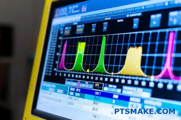
Decoding the Power Graph
The power graph shows the energy drawn by the power supply to maintain ultrasonic amplitude. It should rise smoothly as the plastic melts and then level off.
A sharp, immediate power spike often points to flash. This means the energy director geometry is too aggressive. It melts too quickly before proper bonding can occur.
Conversely, a low, flat power curve suggests insufficient melting. This can result from poor part-to-horn contact. In our experience, low coupling efficiency13 is a frequent cause.
Reading the Collapse Graph
The collapse, or distance, graph tracks the vertical compression of the parts. It is a direct measure of how much material has melted and flowed.
An ideal curve shows a steady downward slope. If the curve is flat, no collapse has occurred. This results in a weak or non-existent weld.
If the collapse happens too fast, you’re likely getting excessive flash. In past projects at PTSMAKE, we’ve correlated this with too much weld pressure or time.
Analyzing the Frequency Graph
The frequency graph monitors the resonant frequency of the acoustic stack. On equipment like a Branson ultrasonic welder, it should remain very stable throughout the weld.
A large frequency shift can signal a problem. This might be a loose horn, a cracked part, or inconsistent part material.
The table below links common graph patterns to specific weld defects.
| Graph Pattern | Potential Weld Defect |
|---|---|
| Early Power Spike | Flash, Misalignment |
| Flat Collapse Curve | Incomplete Weld, Cold Weld |
| Drastic Frequency Change | Cracked Part, Loose Tooling |
| Low Power Draw | Poor Part Contact, No Melt |
By analyzing power, collapse, and frequency graphs, you can diagnose weld issues effectively. Specific patterns, like power spikes or flat collapse curves, directly correlate to common defects such as flash or incomplete welds, enabling precise process adjustments.
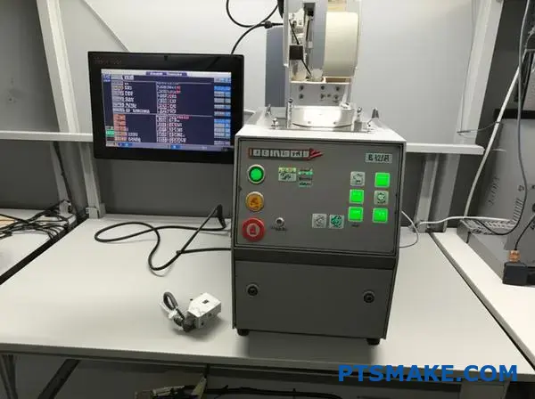
How do you perform and analyze a horn frequency scan?
Running a horn frequency scan is a crucial diagnostic step. It’s the best way to check the health of your ultrasonic horn.
This simple test confirms your horn is resonant and working efficiently. It helps you catch problems like hidden cracks before they lead to production failures.
The Purpose of a Scan
Think of it as an EKG for your welder stack. It ensures every component is working together perfectly.
Key Scan Metrics
A scan provides vital data points for analysis.
| Metric | What It Tells You |
|---|---|
| Frequency | Confirms the horn is tuned correctly. |
| Power | Shows the energy needed to make the horn resonate. |
| Time | The duration of the ultrasonic vibration test. |
Running the Horn Scan
The process is straightforward on most modern welders. On a machine like a branson ultrasonic welder, this is often called ‘Test Sonics’.
First, ensure the converter, booster, and horn are correctly assembled. Proper torque is essential for accurate results.
Next, navigate to the diagnostic menu on your welder. Select the horn scan or test sonics function.
The welder will then send a low-power signal through the stack. It sweeps across a frequency range to find the resonant point. It’s important to run this test with no load on the horn.
Interpreting the Results
A healthy horn will show a single, sharp, and clean peak on the frequency graph. This indicates a clear resonant frequency with low impedance14. The power draw should be minimal.
If you see multiple peaks or a jagged line, it’s a red flag. This often points to a crack in the horn or a loose connection in the stack. A frequency that has shifted significantly from the horn’s stamped value also indicates a problem.
| Scan Result | Indication | Action Required |
|---|---|---|
| Single, Sharp Peak | Healthy Horn | No action needed. |
| Multiple Peaks | Cracked Horn/Loose Stack | Inspect and re-torque stack; replace horn if cracked. |
| Shifted Frequency | Tuning Issue | Check stack components and assembly. |
| High Power Draw | Inefficient Operation | Investigate stack for issues. |
A horn frequency scan is a quick, non-invasive diagnostic tool. It verifies that your horn is resonant, free of cracks, and operating efficiently. Proper analysis of the results is key to preventing downtime and ensuring consistent, high-quality welds in production.
How do you implement SPC using Branson weld data?
Implementing Statistical Process Control (SPC) begins with your data. First, you need to export the weld data from your Branson ultrasonic welder. This data is the foundation for your analysis.
Exporting and Charting
You can typically export this information as a .csv file. This format is easily imported into software like Excel or Minitab. From there, you can create control charts.
The most common charts are X-bar and R charts. These track the process mean (X-bar) and variation (R) over time.
Key Parameters to Monitor
Focus on critical outputs that define weld quality. Here are a few examples we often track in our projects at PTSMAKE.
| Parameter | Why It’s Important |
|---|---|
| Peak Power (W) | Indicates energy delivery consistency. |
| Collapse Distance (mm) | Measures material displacement, key for seal integrity. |
| Weld Time (s) | Tracks the duration of the weld cycle. |
| Frequency (kHz) | Ensures the welder operates at its optimal resonance. |
Monitoring these helps you spot trends before they become defects.
Creating X-bar and R Charts
Once you have your data, the process is straightforward. We use this method to ensure stability for our clients’ high-precision parts. It helps us proactively manage the manufacturing process.
Step 1: Data Collection
First, collect data in subgroups. For instance, measure the collapse distance for 5 consecutive parts. This forms one subgroup. Repeat this at regular intervals.
Step 2: Calculate Averages and Ranges
For each subgroup, calculate the average (X-bar) and the range (R). The range is simply the difference between the highest and lowest values in that subgroup.
Step 3: Plot the Data
Create two charts. On the X-bar chart, you plot the average of each subgroup. On the R chart, you plot the range of each subgroup.
Step 4: Establish Control Limits
After collecting enough data (typically 20-25 subgroups), you can calculate the Upper Control Limit (UCL) and Lower Control Limit (LCL) for both charts. These limits define the expected range of natural process variation.
Any data point falling outside these limits signals a potential problem. It could be due to Assignable Cause Variation15, which needs immediate investigation. This method turns raw data into actionable intelligence.
| Chart Component | Description |
|---|---|
| Center Line (CL) | The overall average of your subgroup averages or ranges. |
| Upper Control Limit (UCL) | Typically CL + 3 standard deviations. |
| Lower Control Limit (LCL) | Typically CL – 3 standard deviations. |
| Data Points | The plotted subgroup averages (X-bar) or ranges (R). |
This structured approach is fundamental to maintaining high quality standards.
Exporting Branson weld data to create X-bar and R charts is crucial. This proactive method allows you to monitor key parameters, establish control limits, and identify process variations before they result in non-conforming parts, ensuring consistent production quality.
How do you advise on part design for optimal welding?
Turning a concept into a robust welded part requires clear, actionable design feedback. It’s about teamwork between your designers and our manufacturing team.
We focus on four critical areas. These areas ensure your product is not only functional but also weldable from the start.
Key Design Considerations
Good design prevents welding failures. We always check joint geometry for proper alignment and contact. Uniform wall thickness is also crucial for even energy transmission.
Material choice and energy director design are the final pieces. They directly impact the final bond strength.
| Design Factor | Primary Goal |
|---|---|
| Joint Geometry | Maximize contact area |
| Wall Thickness | Ensure uniform energy flow |
| Material Selection | Promote molecular bonding |
| Energy Director | Concentrate welding energy |
Providing feedback is a collaborative process. We go beyond simple checklists. We help your team understand the "why" behind each recommendation. This builds better design practices for future projects.
Joint Geometry In-Depth
For ultrasonic welding, a simple butt joint is rarely enough. We often suggest a tongue-and-groove or step joint. These designs help with self-alignment. They also provide a better seal against flash.
Material and Its Impact
Material selection is critical. Amorphous plastics like ABS or polycarbonate generally weld well. However, some materials are Hygroscopic16 and absorb moisture from the air. This moisture can turn to steam during welding, creating a weak, porous bond. Proper material drying is essential.
Energy Director Precision
The energy director is a small, molded feature that concentrates ultrasonic energy. Its shape is vital. Based on our tests using equipment like a branson ultrasonic welder, we provide precise geometry. This ensures a rapid, consistent melt.
| Joint Type | Key Advantage |
|---|---|
| Step Joint | Good alignment and strength |
| Tongue-and-Groove | Excellent alignment and hermetic seal |
| Shear Joint | Creates the strongest possible bond |
At PTSMAKE, we use our experience to guide these details. We aim to make the manufacturing process smooth and predictable for you.
Successful welding is built into the design. By focusing on joint geometry, material properties, and precise energy directors, we ensure a strong, reliable final product. This proactive approach saves time and cost.
Unlock Your Next Project with PTSMAKE Branson Ultrasonic Expertise
Ready to boost your manufacturing precision with Branson ultrasonic welder solutions? Send your RFQ to PTSMAKE today! Our experts streamline your process, ensure part quality, and deliver reliable, high-performance results—perfect for complex or custom requirements. Partner with us and get superior support from prototype to production!

Discover how actuator technology impacts ultrasonic welding precision and quality control. ↩
Learn how this property impacts energy transfer and weld quality. ↩
Discover how this complex material behavior is the key to creating strong ultrasonic bonds. ↩
Understand how this core component converts electrical energy into mechanical vibrations for welding. ↩
Learn how to achieve airtight and watertight welds for your most critical plastic components. ↩
Learn the mechanical principle behind booster mounting for stable and efficient ultrasonic welding. ↩
Learn how material hardness affects fixture design and weld quality for your components. ↩
Learn how servomotors provide the precision needed for modern automated manufacturing. ↩
Learn how this data profile helps diagnose weld faults and optimize your manufacturing process. ↩
Learn more about creating robust safety circuits in automated systems. ↩
Learn how this micro-motion-induced corrosion can cause joint failure and how to prevent it. ↩
Learn how this property impacts energy transfer and weld quality in our detailed guide. ↩
Discover how optimizing energy transfer between the horn and parts improves weld strength and consistency. ↩
Understand how electrical impedance is a key factor in ultrasonic welding efficiency. ↩
Understand the types of process variations that signal a need for immediate investigation and corrective action. ↩
See how moisture in plastics can impact the quality and success of your welded joints. ↩