Many engineers struggle with bevel gear failures, unexpected noise, and premature wear in their precision systems. These issues often stem from overlooking the complex three-dimensional force interactions and geometric constraints that make bevel gears fundamentally different from spur or helical gears.
Bevel gears solve the critical challenge of transmitting power between intersecting shafts through their conical tooth geometry, enabling efficient torque transfer at various angles while managing complex radial, tangential, and axial force combinations that would be impossible with traditional parallel-axis gear systems.
I’ve worked with engineers who’ve spent months troubleshooting bevel gear systems, only to discover the root cause was a basic design oversight. This guide walks you through 15 essential questions that separate successful bevel gear implementations from costly failures, covering everything from fundamental force analysis to advanced optimization techniques.
What problem does a bevel gear solve over other gear types?
Gears are essential for power transmission. But what happens when the shafts intersect, often at a 90-degree angle? Common gear types like spur or helical gears simply cannot work in this scenario. Their design is for parallel shafts.
This is the specific problem that bevel gears solve. Their unique conical shape is the fundamental solution. It enables smooth and efficient power transfer around corners. This core function makes them irreplaceable in many mechanical systems.
| Gear Type | Shaft Orientation | Primary Application |
|---|---|---|
| Spur Gear | Parallel | Simple, parallel power transfer |
| Bevel Gear | Intersecting | Power transfer at an angle |
The Geometric Challenge of Intersecting Shafts
Imagine forcing two spur gears to mesh at a 90-degree angle. Their teeth are cut straight across a cylindrical shape. They are designed for contact along parallel axes. At an intersection, their teeth would grind or make minimal contact. This leads to inefficient power transfer and rapid wear.
Helical gears, though quieter, face a similar limitation. Their angled teeth are perfect for parallel shafts but are not designed for the geometry of intersecting shafts. The fundamental design principle doesn’t match the application.
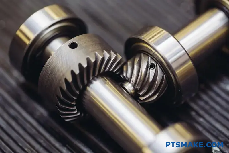
The Bevel Gear’s Conical Solution
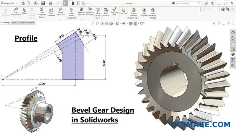
This is where expert Bevel Gears design becomes critical. Instead of a cylinder, bevel gear teeth are cut on a cone. This change is the key to their function. Two conical gears can mesh perfectly where their shafts intersect. Their teeth engage smoothly along their face width.
This entire concept works because of the pitch cone1. The teeth of a bevel gear all taper toward a common point, the apex of the cone. When two gears mesh, their apexes meet at the same point. This alignment ensures a continuous, rolling contact.
Basic Gear Geometry Comparison
| Feature | Spur Gear | Bevel Gear |
|---|---|---|
| Base Shape | Cylinder | Cone |
| Shaft Angle | 0° (Parallel) | Typically 90° |
| Tooth Path | Straight | Tapered toward apex |
Bevel gears address the unique challenge of transmitting power between intersecting shafts. Where cylindrical gears like spur and helical fail, the conical geometry of bevel gears allows for smooth, effective engagement at an angle, making them essential for right-angle applications.
What are the fundamental forces acting on a bevel gear tooth?
When you transmit power through bevel gears, the load on a tooth is complex. It isn’t a single, straightforward push.
Instead, this load splits into three fundamental components. These are the tangential, radial, and axial forces.
Each force acts in a unique direction. Understanding them is not optional; it’s a cornerstone of reliable bevel gears design. It ensures your assembly is robust and performs as intended.
| Force Component | Primary Direction of Action |
|---|---|
| Tangential (Ft) | Acts along the tangent to the pitch circle |
| Radial (Fr) | Acts toward the center of the gear |
| Axial (Fa) | Acts along the gear’s shaft axis |
The Origin of Each Force Component
Let’s break down where each force comes from. Getting this right is critical for the mechanical integrity of the entire system.
Tangential Force (Ft)
This is the useful component. The tangential force is what actually transmits the torque and power. It’s directly proportional to the torque being applied to the gear.
Radial Force (Fr)
The pressure angle of the gear teeth creates a separating force. The radial component is the part of this force that pushes the two gears directly away from each other, perpendicular to their shafts.
Axial Force (Fa)
The cone angle of bevel gears also generates a thrusting force. This axial force pushes each gear along its shaft axis. This is a critical factor that differentiates bevel gears from simple spur gears.
At PTSMAKE, we always analyze the combined resultant force2 during the design phase. This analysis is crucial for selecting appropriate bearings and designing a housing that won’t flex under load.
| Design Element | Key Forces to Consider | Why It Is Critical |
|---|---|---|
| Bearing Selection | Radial & Axial | Tapered roller bearings are often needed to handle the combined loads. |
| Shaft Deflection | Tangential & Radial | The shaft must be stiff enough to resist bending and maintain gear alignment. |
| Housing Design | All Three | The housing must securely support the bearings and prevent misalignment. |
Summary of Forces on a Bevel Gear Tooth
Properly identifying the tangential, radial, and axial forces is essential. These three components directly influence bearing selection, shaft strength, and housing rigidity, which are foundational for a durable and efficient bevel gear system. Neglecting any one of them can lead to premature failure.
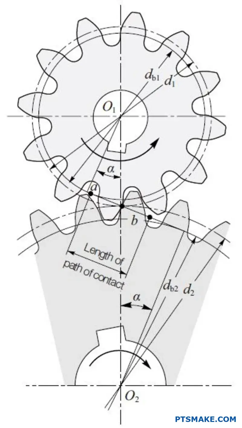
How does ‘contact ratio’ relate to smooth bevel gear operation?
Contact ratio is the average number of teeth in contact at any one time. Think of it as a measure of overlap. A higher ratio is always better.
It directly improves performance. More teeth sharing the load means smoother power transmission. This reduces vibration and noise significantly.
The Impact of Contact Ratio
A higher contact ratio lowers the stress on each individual tooth. This extends the gear’s operational life and improves reliability.
| Contact Ratio | Operational Effect | Benefit |
|---|---|---|
| Low (< 1.2) | Rough, Noisy | Lower Cost |
| High (> 1.2) | Smooth, Quiet | Increased Durability |
This simple factor is critical in high-performance Bevel Gears design.
Deeper Dive into Load Sharing
A higher contact ratio means the load is distributed across multiple teeth pairs. One pair of teeth is already in full contact before the preceding pair disengages.
This overlap is the key. It prevents abrupt load transfers. Abrupt transfers are a major source of noise and impact stress in gear systems.
At PTSMAKE, we focus on maximizing this overlap. Proper Bevel Gears design ensures a seamless transition of power from one tooth to the next.
How Contact Ratio Reduces Wear
With the load shared, the peak stress on any single tooth is much lower. This reduces the risk of pitting, scoring, and eventual tooth failure. It’s a fundamental principle for durability.
The entire meshing cycle3 becomes smoother. There’s less instantaneous pressure, which also minimizes heat generation and material fatigue over millions of cycles.
| Feature | Low Contact Ratio | High Contact Ratio |
|---|---|---|
| Load Distribution | Concentrated on one pair | Shared across 1-2 pairs |
| Noise Level | Higher | Lower |
| Vibration | Significant | Minimal |
| Wear Rate | Faster | Slower |
| Gear Lifespan | Shorter | Longer |
This table clearly shows the benefits. Achieving a higher contact ratio is a primary goal in our design and manufacturing process.
A higher contact ratio directly results in smoother, quieter gear operation. By ensuring more teeth are engaged at once, it distributes the load, reduces stress on individual teeth, and significantly enhances the overall durability and performance of the gear set.
What defines the ‘pressure angle’ in a bevel gear system?
The pressure angle is a fundamental parameter in Bevel Gears design. It dictates how force is transmitted between meshing teeth.
Imagine two gears meeting. The pressure angle is the angle between the line of force and the line tangent to the pitch circles at the point of contact. This angle determines much about the gear’s performance.
The Angle of Force
This angle is critical. It directly influences how loads are distributed across the gear system. A slight change here can have significant ripple effects on the entire mechanism.
| Component | Description |
|---|---|
| Line of Force | The direction of the force exerted by the driving tooth on the driven tooth. |
| Tangent Line | A line tangent to both pitch circles at the pitch point. |
| Pressure Angle | The angle between these two lines. |
Choosing the right pressure angle is a trade-off. In past projects at PTSMAKE, we’ve helped clients balance these factors to achieve optimal performance for their specific applications.
Impact on Tooth Strength
A larger pressure angle, like 25°, results in a wider and stronger tooth base. This significantly improves resistance to bending stress. A smaller angle, like the common 20°, produces a finer tooth profile.
Bearing Load Considerations
However, a larger pressure angle also increases the radial load on bearings. This force pushes the gears apart. The system’s bearings and housing must be strong enough to handle this increased load without deflection. The line of action4 becomes steeper.
The Risk of Undercutting
Undercutting is a manufacturing issue. It happens when designing gears with a low tooth count and a small pressure angle. The cutting tool can remove material from the base of the tooth, weakening it severely.
Here’s a quick comparison of common pressure angles:
| Pressure Angle | Tooth Strength | Bearing Load | Undercutting Risk (with low tooth count) |
|---|---|---|---|
| 14.5° | Lower | Lower | High |
| 20° | Standard | Standard | Moderate |
| 25° | Higher | Higher | Low |
This balance is crucial. It ensures the final gear is both manufacturable and durable enough for its intended purpose.
The pressure angle defines the force transmission path in bevel gears. This single parameter directly impacts tooth strength, the load placed on bearings, and the potential for manufacturing defects like undercutting. Careful selection is essential for reliable gear system design.
When do you choose a spiral bevel over a straight bevel gear?
Choosing the right gear is critical. It often comes down to balancing performance needs with your budget. The decision is simpler than you might think.
Spiral bevel gears are for demanding applications. Think high speeds, heavy loads, and the need for quiet operation.
Straight bevel gears are the practical choice. They are perfect for simpler, lower-speed systems where cost is a major factor.
A quick comparison can guide your bevel gears design.
| Feature | Spiral Bevel Gear | Straight Bevel Gear |
|---|---|---|
| Operation | Smooth & Quiet | Noisier |
| Load Capacity | Higher | Higher |
| Cost | Higher | Lower |
| Best For | High-Speed, Heavy-Load | Low-Speed, Simple Systems |
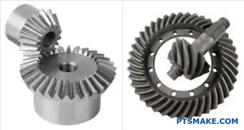
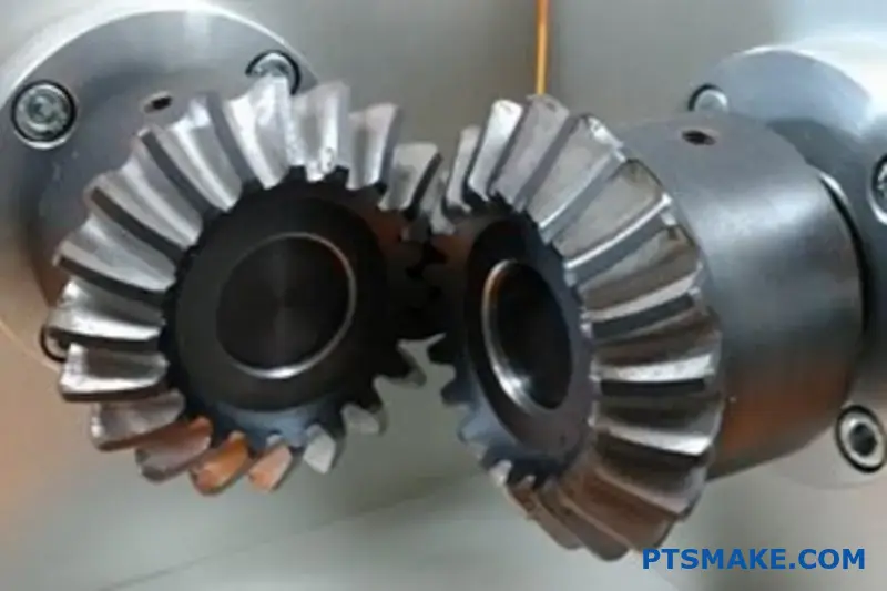
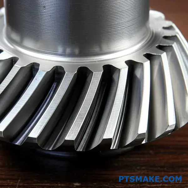
The key difference is how the gear teeth engage. Spiral bevel gears have curved teeth. This allows them to mesh gradually and smoothly.
This gradual engagement minimizes impact and vibration. It’s the reason they operate so quietly, making them ideal for high-performance systems like vehicle transmissions or robotic arms.
Straight bevel gears have straight teeth. They engage along the entire tooth face at once. This abrupt contact generates more noise and vibration.
Spiral gears also have a higher contact ratio5. This means more teeth are in contact at any given moment, distributing the load more effectively. Our analysis shows this significantly increases their load-carrying capacity.
Of course, this advanced design has manufacturing implications. The complex curvature of spiral gears requires precision 5-axis CNC machining. At PTSMAKE, we have extensive experience creating these high-tolerance parts.
Straight gears are simpler to manufacture. This directly translates to a lower cost, making them a great fit for many industrial applications where high speed isn’t a priority.
| Criterion | Spiral Bevel Gear | Straight Bevel Gear |
|---|---|---|
| Tooth Contact | Gradual, Point Contact | Abrupt, Line Contact |
| Noise Level | Low | High |
| Vibration | Minimal | Significant |
| Manufacturing | Complex (5-axis CNC) | Simpler |
| Ideal Speed | High RPM | Low to Moderate RPM |
Your choice hinges on a simple trade-off. Spiral bevel gears offer superior performance in noise, load, and smoothness at a higher cost. Straight bevel gears provide a reliable, economical solution for less demanding applications where budget is a primary concern.
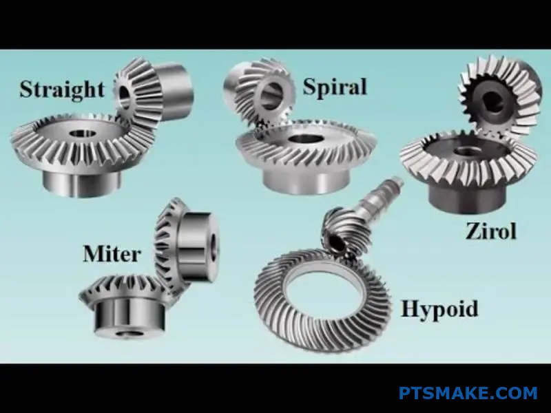
What are the specific applications for Zerol and hypoid bevel gears?
Zerol and hypoid gears represent advanced gear engineering. They solve problems that standard bevel gears cannot. But they are not interchangeable.
Each type has unique geometric properties. These properties define its ideal use.
Understanding their core differences is key. This knowledge ensures you select the optimal gear for your specific application’s demands. Proper selection impacts performance and longevity.
The Zerol Bevel Gear Advantage
Zerol gears are a special type of spiral bevel gear. They have a zero spiral angle. This design combines the best of straight and spiral gears.
| Feature | Straight Bevel Gear | Spiral Bevel Gear | Zerol Bevel Gear |
|---|---|---|---|
| Spiral Angle | 0° | > 0° | 0° |
| Tooth Contact | Abrupt | Gradual | Gradual |
| Thrust Load | Moderate | High | Moderate |
Hypoid Bevel Gears Explained
Hypoid gears are designed for shafts that are offset. This means their axes do not intersect. This offset is their defining feature.
Diving deeper, the differences become even more critical for effective Bevel Gears design. The choice between them often comes down to specific operational requirements like noise, load, and shaft configuration.
Zerol Gears: A Hybrid Solution
Zerol gears have curved teeth but a zero spiral angle. This gives them the gradual tooth engagement of spiral gears. This means they run smoother and quieter than straight bevel gears.
However, they maintain the same thrust load characteristics as straight bevel gears. This simplifies bearing and mounting requirements compared to spiral bevel gears. At PTSMAKE, we often recommend Zerol gears for high-speed, high-load applications where reversing direction is necessary.
Hypoid Gears: For Offset Power
Hypoid gears are true specialists. Their non-intersecting shaft design is a major advantage in many automotive and industrial applications. The offset allows for larger and stronger pinions.
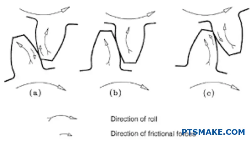
This geometry results in a unique sliding action between teeth. This, combined with a high contact ratio, allows for incredible torque transmission. They operate very quietly. However, this sliding requires specialized lubrication to manage friction and wear. The design also generates significant Axial thrust6, a critical factor in system design.
| Parameter | Zerol Bevel Gear | Hypoid Bevel Gear |
|---|---|---|
| Shaft Axes | Intersecting | Non-Intersecting (Offset) |
| Spiral Angle | Zero | Non-Zero |
| Tooth Action | Mostly Rolling | Rolling and Sliding |
| Key Benefit | Smooth operation, moderate thrust | High torque, quiet, compact design |
| Common Use | Power tools, machine tools | Automotive differentials, industrial drives |
Zerol gears offer a balanced solution, combining the benefits of straight and spiral types. Hypoid gears, in contrast, are specialized for non-intersecting shafts, delivering high torque and quiet operation through a unique sliding tooth action.
How do AGMA standards classify bevel gear quality for different applications?
The AGMA Quality Number, or Q-number, is the core of gear classification. It’s a simple scale, usually from 3 to 15.
A higher Q-number means tighter tolerances and higher precision. This directly translates to better gear performance.
Think of it as a grading system. It provides a clear, standardized language for everyone involved. This helps in the bevel gears design phase.
Understanding Q-Numbers
This system specifies exact tolerances for several key geometric features. This ensures consistency and reliability in manufacturing.
Here’s a quick overview of what different Q-numbers imply.
| Q-Number | Precision Level | Typical Application |
|---|---|---|
| Q5-Q7 | Commercial | Power tools, agricultural machinery |
| Q8-Q10 | Precision | Automotive transmissions, industrial gearboxes |
| Q11-Q13 | High Precision | Aerospace, medical devices, robotics |
| Q14-Q15 | Ultra Precision | Master gears, instrumentation |
This framework is essential for matching gear quality to its intended function.
The Q-number isn’t just a random grade. It’s a comprehensive framework that defines acceptable deviations in a gear’s physical characteristics. This directly influences how the gear will behave in a real-world application.
Key Parameters Governed by Q-Numbers
AGMA standards detail tolerances for several factors. Three of the most critical are tooth geometry, runout, and spacing. Each one affects the final performance.
Tighter tolerances on these parameters reduce operational noise and vibration. They also increase the gear’s load-carrying capacity and lifespan. At PTSMAKE, we help clients select the right Q-number. This ensures they don’t over-engineer and overpay.
A critical parameter measured is the Total Composite Error7. This value captures the combined variations from the ideal gear profile during one full rotation.
Impact Across Industries
The required Q-number varies significantly depending on the industry. This balance between cost and performance is crucial.
| Industry | Typical Q-Number | Rationale |
|---|---|---|
| Aerospace | Q11 – Q13 | High reliability, low vibration, and safety are critical. |
| Automotive | Q8 – Q10 | Balance of performance, noise reduction, and mass-production cost. |
| Medical Devices | Q10 – Q12 | Precision movement and quiet operation are paramount. |
| Agricultural | Q5 – Q7 | Durability is key, but cost is a major driver. High precision is not needed. |
Choosing the appropriate Q-number is a foundational step in successful bevel gears design. It prevents costly errors down the line.
The AGMA Q-number system provides a vital framework. It allows engineers to specify gear quality precisely, balancing performance requirements with manufacturing costs. This ensures the final product is perfectly suited for its intended application, from farm equipment to spacecraft.
What material properties are most critical for bevel gear design?
When choosing materials for bevel gears, it’s about making smart trade-offs. You need to prioritize. The goal is to balance properties for optimal performance and a long service life. It’s not just about strength.
Surface Durability for Wear
A hard surface is essential. It fights the constant wear and pitting from tooth-on-tooth contact. This property directly relates to the gear’s operational lifespan.
Core Strength for Fatigue
Beneath the surface, you need toughness. This core strength helps the gear tooth resist bending and absorb shock loads without fracturing.
| Property | Key Role | Prevents This Failure |
|---|---|---|
| Surface Hardness | Resists wear and pitting | Surface fatigue, abrasion |
| Core Toughness | Absorbs shock and bending | Tooth fracture |
A material might look great in a datasheet, but practical factors are just as important. In our projects at PTSMAKE, we always consider how a material behaves during manufacturing. This can make or break a project’s budget and timeline.
Balancing Practical Constraints
Two major factors are machinability and how the material responds to heat treatment. These properties determine the efficiency and cost of producing the final part. A poor choice here can create unexpected delays and expenses.
Considering Machinability
Good machinability is crucial for any Bevel Gears design. It allows for faster production, less tool wear, and ultimately, a more cost-effective part. Materials that are difficult to machine increase both time and cost. We’ve found that pre-hardened steels often offer a good compromise.
Evaluating Heat Treatment Response
Heat treatment is where we activate the gear’s key properties. It creates the hard, wear-resistant surface while keeping a tough, ductile core. A material with a predictable response to heat treatment ensures consistent quality. This process is vital for preventing catastrophic failures from issues like bending fatigue8.
| Manufacturing Factor | Impact on Bevel Gear Production | Desired Outcome |
|---|---|---|
| Machinability | Influences cost and lead time | Faster machining, lower tool cost |
| Heat Treatment Response | Determines final mechanical properties | Consistent hardness and toughness |
For effective bevel gear design, you must balance surface hardness against core toughness. Additionally, consider practical factors like machinability and heat treatment response, as they heavily influence manufacturing costs, timelines, and the final quality of the gear.
What are the common types of bearing arrangements for bevel gears?
Bevel gears generate both radial and axial forces. This is a key challenge in their design. You can’t just use any bearing. The arrangement must handle these combined loads effectively.
Proper support is crucial for gear mesh alignment and long life. Without it, the gears will wear quickly and fail. We need a robust solution.
The choice of bearings directly impacts performance. Let’s look at the most common combinations that provide stability and manage these forces.
| Load Type | Direction of Force | Typical Bearing Solution |
|---|---|---|
| Radial | Perpendicular to the shaft | Deep Groove Ball, Cylindrical Roller |
| Axial (Thrust) | Parallel to the shaft | Tapered Roller, Angular Contact Ball |
This combination of forces makes tapered roller bearings an excellent choice.
Tapered Roller Bearings: The Ideal Choice
In many projects at PTSMAKE, we recommend tapered roller bearings for bevel gear applications. Their design inherently handles both high radial and high axial loads simultaneously. This makes them perfect for the job.
The angled raceways guide the rollers to manage thrust. This is a fundamental aspect of a successful Bevel Gears design. It ensures the gear set remains stable under load.
Common Mounting Arrangements
To counteract the strong thrust forces, these bearings are often used in pairs. The mounting configuration is critical. Setting the right amount of preload9 is essential for stiffness and longevity.
Back-to-Back (DB) Mounting
In this setup, the contact angle lines diverge. This creates a wide, rigid base. It’s excellent for handling moment loads, which is common when the gear is overhung on the shaft.
Face-to-Face (DF) Mounting
Here, the contact angle lines converge. This arrangement is more forgiving of shaft misalignment. However, it offers less resistance to moment loads compared to the DB configuration.
| Arrangement | Rigidity | Misalignment Tolerance | Typical Use Case |
|---|---|---|---|
| Back-to-Back (DB) | High | Low | Overhung pinion gears |
| Face-to-Face (DF) | Moderate | High | Straddle-mounted gears |
Each setup has its place. The final choice depends on the specific application’s load and alignment requirements.
Tapered roller bearings, typically mounted back-to-back, are the go-to solution for bevel gears. This arrangement effectively manages the combined radial and axial loads, ensuring rigidity, proper gear mesh, and a long operational life for the entire assembly.
How are bevel gear sets specified on a technical drawing?
A technical drawing is the single source of truth for manufacturing. For complex parts like bevel gears, it’s absolutely critical. Every detail matters.
Omitting information creates ambiguity. This leads to production errors, delays, and parts that don’t work. The goal is to provide a complete and clear blueprint.
This ensures the manufacturer can produce the gears exactly as you designed them. Below are the core specifications that must be included on every drawing for a bevel gear set.
| Gear Parameter | Gear | Pinion |
|---|---|---|
| Number of Teeth | XX | XX |
| Diametral Pitch | XX | XX |
| Pressure Angle | XX° | XX° |
| Face Width | X.XXX | X.XXX |

A drawing for a bevel gear set must contain much more than just basic dimensions. It needs to detail every aspect of the gear’s geometry, material, and required quality. This comprehensive information guides the entire manufacturing process.
Essential Geometric and Mating Data
The drawing must specify fundamental gear data. This includes the number of teeth for both the gear and the pinion, the diametral pitch, and the pressure angle. These define the gear ratio and tooth profile.
Cone angles (pitch, root, and face angles) are also vital. They dictate the gear’s shape. Crucially, the mounting distance must be specified with a tight tolerance. It ensures the gear and pinion align correctly in the assembly. A small deviation here can lead to premature wear or failure.
Material, Treatment, and Quality Requirements
The drawing must clearly state the material choice and any required heat treatment. This determines the gear’s strength, durability, and wear resistance.
You also need to define the allowable backlash10. This small gap between mating teeth is essential. It prevents binding and allows space for lubrication.
Finally, the AGMA (American Gear Manufacturers Association) quality number is required. This number sets the standard for manufacturing tolerances and accuracy. At PTSMAKE, we use this number to ensure our bevel gears design and production meet your exact performance needs.
| Specification | Importance |
|---|---|
| Material Specification | Defines strength and durability. |
| Heat Treatment | Hardens the gear surface for wear resistance. |
| AGMA Quality Number | Sets the tolerance and precision standard. |
In summary, a comprehensive technical drawing is non-negotiable. Including all geometric, material, and quality specifications ensures that the final bevel gears are manufactured correctly and perform reliably in their application. This is a cornerstone of successful engineering.
How do you calculate the required gear ratio and select tooth numbers?
Calculating your gear ratio and selecting tooth numbers is a foundational step. It directly translates your speed and torque needs into a physical design. Get this wrong, and your machine won’t perform as intended.
The process is simpler than it seems. It starts with your desired input and output speeds. From there, we move to the physical gears.
The Core Calculation
First, determine the required gear ratio. This is a simple division of speeds.
Gear Ratio (i) = Input Speed (n1) / Output Speed (n2)
This ratio is the target. Now, we find the tooth numbers that achieve it.
Selecting the Right Teeth
The same ratio can be achieved with different tooth counts. For example, a 2:1 ratio could be 20 and 40 teeth, or 30 and 60. The choice impacts size, strength, and wear.
The goal is to translate your required speed reduction or increase into a tangible gear set. This involves more than just simple math; it’s about creating a durable and efficient system.
Step 1: Define the Gear Ratio
Your starting point is always the operational speeds. If you have a motor running at 1800 RPM (input) and you need to drive a conveyor at 600 RPM (output), the calculation is straightforward.
| Parameter | Value |
|---|---|
| Input Speed (n1) | 1800 RPM |
| Output Speed (n2) | 600 RPM |
| Required Ratio (i) | 1800 / 600 = 3 |
Your target gear ratio is 3:1.
Step 2: Select Tooth Numbers
Now, select tooth numbers for the driver (pinion) and driven gear. The ratio of teeth must equal your target gear ratio.
Gear Ratio (i) = Teeth on Driven Gear (Z2) / Teeth on Pinion (Z1)
For a 3:1 ratio, you could use a 20-tooth pinion and a 60-tooth driven gear. This is a good starting point.
Step 3: Refine and Verify
Avoid having the tooth counts be exact multiples if possible. Using a hunting tooth combination11 helps distribute wear evenly. For instance, instead of 20/60, a 21/63 pair still gives a 3:1 ratio and can improve wear patterns.
Also, ensure the pinion has enough teeth to avoid undercutting, which weakens the tooth base. The minimum number depends on the pressure angle. This principle is vital in all gear manufacturing, including complex bevel gears design.
| Pressure Angle | Minimum Pinion Teeth |
|---|---|
| 14.5° | 32 |
| 20° | 18 |
| 25° | 12 |
Calculating the gear ratio from speeds is the first step. Then, you must carefully select tooth numbers that not only achieve this ratio but also ensure longevity by avoiding issues like undercutting and promoting even wear patterns.
How would you optimize a bevel gear design for noise reduction?
For a high-performance gearbox, a comprehensive strategy is key. We can’t just fix one thing. It’s about a total system approach.
Boosting Contact Ratio
Using spiral bevel gears is a great start. Their curved teeth engage gradually. This increases the contact ratio, leading to smoother, quieter operation. A good Bevel Gears design focuses on this principle.
The Role of Housing Rigidity
A rigid housing is also crucial. It minimizes vibration and deflection under load. This prevents misalignment and reduces system noise.
| Feature | Impact on Noise |
|---|---|
| Spiral Gears | Reduces |
| Rigid Housing | Reduces |
| Higher AGMA Quality | Reduces |
This multi-faceted approach ensures a truly quiet gearbox.
A Deeper Dive into Advanced Optimization
A successful quiet gearbox design goes beyond the basics. It requires a detailed focus on several interacting factors. At PTSMAKE, we integrate these elements from the start.
Refining the Tooth Profile
The tooth profile itself is critical. We aim to minimize transmission error12. This is the slight deviation from perfectly uniform motion as teeth engage and disengage.
By carefully modifying the tooth profile, sometimes called crowning or tip relief, we can smooth this transfer of motion. This significantly cuts down on the primary source of gear whine.
Specifying Higher AGMA Quality
We also specify a higher AGMA (American Gear Manufacturers Association) quality level. A higher number means tighter tolerances and a more precise gear. While it may increase manufacturing cost, the noise reduction is substantial.
| AGMA Level | Precision | Typical Application |
|---|---|---|
| AGMA 8-9 | Medium | General Industrial |
| AGMA 10-12 | High | Automotive Transmissions |
| AGMA 13+ | Very High | Aerospace, Instrumentation |
Based on our tests with clients, moving from AGMA 9 to AGMA 11 can reduce noise levels by several decibels. It’s an investment in performance and user experience. A rigid housing then supports this precision, preventing the high-quality gears from being compromised by system flex.
This holistic strategy—combining spiral gears, a refined tooth profile, high AGMA quality, and a rigid housing—is how we deliver exceptionally quiet and reliable gearbox solutions.
To achieve a quiet gearbox, one must combine strategies. Using spiral gears for a higher contact ratio, refining the tooth profile, specifying a higher AGMA quality level, and ensuring housing rigidity all work together to effectively reduce noise and vibration.
Given an existing gearbox, how would you reverse-engineer its bevel gears?
When a critical bevel gear fails, downtime isn’t an option. The fastest solution is often to reverse-engineer a replacement. This process is a blend of precise measurement and material science.
It begins with a careful inspection of the existing part. We need to get the fundamental data right from the start.
The Replacement Part Scenario
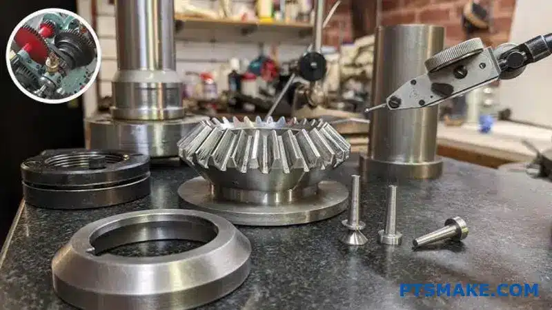
Step 1: Foundational Measurements
The first step is to capture the gear’s core geometry. Precision here is non-negotiable, as small errors can lead to big problems in the final gearbox assembly.
| Key Dimension | Common Tool | Purpose |
|---|---|---|
| Outside Diameter (OD) | Digital Calipers | Defines the gear’s overall size. |
| Cone Angles | CMM or Sine Bar | Ensures correct tooth meshing. |
| Tooth Count | Manual Count | Determines the gear ratio. |
These measurements provide the basic blueprint for the new part.
Advanced Data Capture for a Perfect Replica
With the basic dimensions recorded, we move to more advanced analysis. This is where we capture the intricate details that define the gear’s performance and longevity. A successful Bevel Gears design depends on this phase.
Step 2: Mapping the Tooth Profile
We use a Coordinate Measuring Machine (CMM) or a specialized gear inspection machine. These tools trace the exact shape of the gear tooth, capturing its complex curves with micron-level accuracy. This data creates a precise 3D model, essentially a digital twin of the tooth.
Step 3: Analyzing the Material
A gear’s material is just as important as its shape. Using spectrometry13 or other material analysis techniques, we determine the exact alloy composition. We also check for evidence of surface hardening or other heat treatments. Making a replacement from the wrong material is a recipe for another failure.
From Data to a Manufacturing Drawing
Step 4: Creating the Blueprint
All the dimensional and material data is compiled into a comprehensive CAD model. From this, we create a final manufacturing drawing. This blueprint includes all dimensions, geometric tolerances, material specifications, and required surface finishes. At PTSMAKE, this drawing is the guide we use to machine a perfect, reliable replacement part.
Creating a replacement bevel gear starts with precise manual measurements. This is followed by advanced CMM analysis to map the tooth profile and material testing to identify its composition. Finally, all data is integrated into a detailed manufacturing drawing for production.
How would you design a bevel gear set for a limited-life application?
In some fields, "infinite life" is not the goal. Think of a missile actuator or a racing gearbox. Here, performance is everything.
We intentionally design closer to the material’s limits. This approach accepts a finite lifespan. The reward is significant savings in weight and space.
The Trade-Off Principle
This is a core concept in specialized Bevel Gears design. You trade longevity for immediate performance gains. It’s a calculated decision, not a compromise on quality.
| Design Goal | Infinite Life | Limited-Life |
|---|---|---|
| Primary Focus | Durability | Performance |
| Weight/Size | Secondary Concern | Critical Factor |
| Operational Life | Years/Decades | Hours/Cycles |
This shift in thinking allows for more compact and efficient systems where every gram matters.

Pushing Material Boundaries Safely
Designing for a finite life means we challenge traditional safety factors. Instead of a large buffer, we use a much smaller, calculated one. This allows the gear to handle higher loads relative to its size.
We operate closer to the material’s yield strength. We accept that the gear will experience fatigue and eventually fail. The key is that this failure is predictable and occurs after its mission is complete.
For these projects, we analyze the exact number of cycles and peak loads the gear will face. This data dictates the design. The Allowable Bending Stress14 is set just high enough for the mission. It is not set for perpetual use.
Safety Factors in Context
A lower safety factor is not unsafe. It is simply optimized for the application’s specific, limited lifespan. In our work at PTSMAKE, we help clients define these parameters.
| Application | Typical Safety Factor (Bending) | Design Philosophy |
|---|---|---|
| Industrial Conveyor | 2.0 – 3.0+ | Infinite Life |
| Automotive Transmission | 1.25 – 1.5 | High-Cycle Durability |
| Racing Gearbox | 1.1 – 1.25 | Limited-Life, High Perf. |
| Missile Actuator | 1.0 – 1.1 | One-Time Use |
This tailored approach is fundamental to achieving peak performance in mission-critical, short-term applications. It’s a strategic part of advanced engineering.
Designing for a limited life is a strategic choice. It involves reducing safety factors and pushing materials closer to their limits. This method saves critical weight and space in performance-driven applications like aerospace and racing, accepting a predictable, finite operational lifespan.
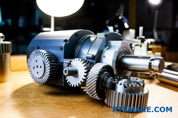
How does the ‘system’ (motor, shaft, housing) influence gear design choices?
A gear never works alone. It’s part of a larger system. Thinking about the motor, shaft, and housing is key. This holistic view prevents many common failures.
The System as a Whole
We must see the entire mechanical assembly. The engine’s power delivery is not smooth. The housing is not perfectly rigid. These factors directly impact gear performance and life.
Key System Interactions
Understanding these inputs is crucial from the start.
| System Component | Influence on Gear Design |
|---|---|
| Engine/Motor | Vibrations, torque fluctuations |
| Shaft | Bending, misalignment |
| Housing | Deflection, thermal expansion |
This approach ensures the gear is designed for its real environment.
Adopting a Holistic Design Philosophy
A truly robust gear is designed with its entire operating context in mind. This means looking beyond just the gear’s material and geometry. It means analyzing the dynamics of the complete system.
For example, an engine doesn’t produce perfectly smooth power. It creates torsional vibrations15 that travel through the shaft to the gear teeth. If we ignore this, we risk tooth fatigue and premature failure. We have to account for these dynamic loads.
Housing Flexibility and its Impact
Similarly, a lightweight housing might seem efficient. But it will flex under load. This flexibility can cause shaft misalignment. Even minor misalignment is a major problem, especially in sensitive applications like Bevel Gears design. It leads to uneven load distribution across the gear tooth face.
Designing for Dynamic Reality
To counter these issues, we modify the gear tooth profile. This is where experience comes in.
| System Dynamic | Required Gear Modification |
|---|---|
| Torsional Vibration | Adjusting dynamic factors, adding profile crowning |
| Housing Flex | Lead correction, helix angle modification |
| Shaft Bending | End relief, tooth crowning |
These adjustments compensate for system-induced stresses. They ensure the gear mesh remains optimal even when the system is under strain. At PTSMAKE, we integrate these system dynamics into our simulation and manufacturing processes.
A gear’s success depends on looking at the whole system. Ignoring factors like engine vibrations or housing flex leads to designs that fail in the real world. A holistic approach is not optional; it is essential for creating reliable and durable gear systems.
Unlock Precision Bevel Gear Solutions with PTSMAKE
Ready to elevate your next project with expertly engineered bevel gears or precision-machined components? Contact PTSMAKE today for a fast, detailed quote! Experience our expertise in CNC machining and injection molding—trusted by industry leaders for quality, reliability, and exceptional customer support.

Learn about the pitch cone, the foundational geometry that allows bevel gears to work. ↩
Explore how this combined force is calculated and its impact on stress analysis. ↩
Understand the gear tooth engagement and disengagement process in more detail. ↩
Get a deeper technical breakdown of how the line of action is determined. ↩
Learn how contact ratio impacts gear strength, noise levels, and overall performance in your designs. ↩
Learn how this force impacts bearing selection and overall gear system design. ↩
Learn how this single measurement reveals the overall accuracy of a gear. ↩
Learn how cyclic stresses cause gear failure and which properties help prevent it. ↩
Learn how proper bearing preload prevents chatter and improves rotational accuracy. ↩
Learn how to specify the correct amount of backlash for optimal gear performance and lifespan. ↩
Discover how this technique minimizes wear and extends the service life of your gear systems. ↩
Learn how this key metric directly impacts gear noise and performance. ↩
Learn how this analysis identifies material composition to prevent premature part failure. ↩
Understand the calculations and factors that determine safe stress levels in gear design. ↩
Understand the critical impact of these vibrations on mechanical system performance. ↩