Worm gear systems can make or break precision machinery performance. Poor design choices lead to catastrophic failures, excessive wear, and costly downtime that disrupts entire production lines.
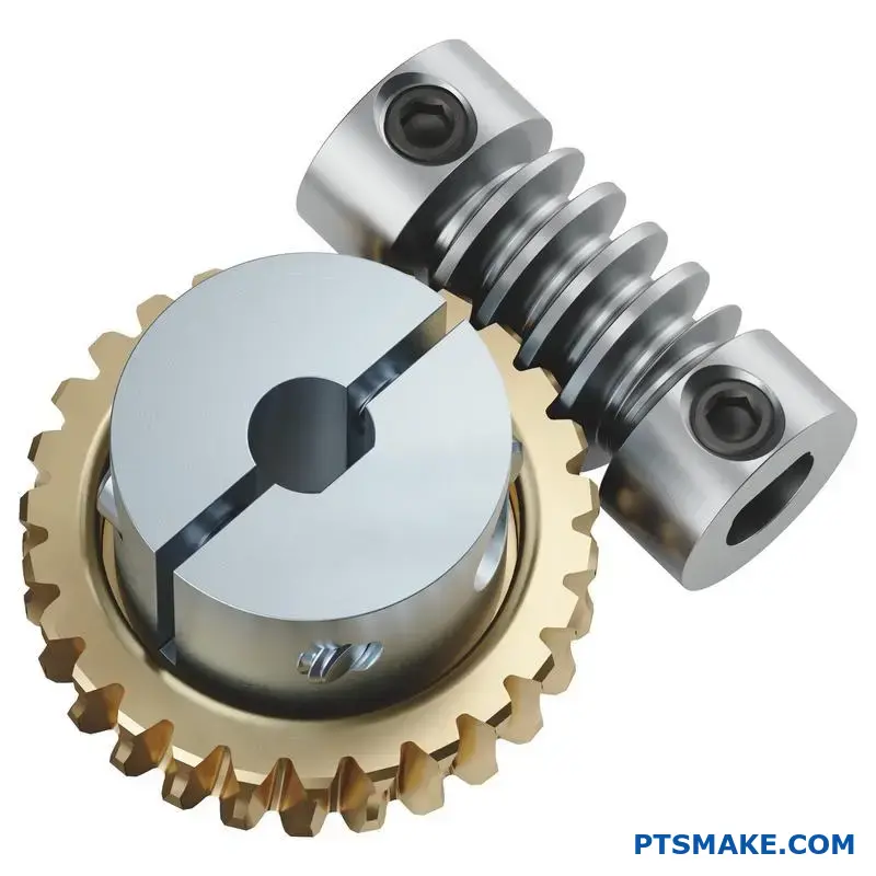
A worm gear is a mechanical power transmission system where a threaded screw (worm) meshes with a toothed wheel, creating high reduction ratios through sliding contact that enables precise motion control and self-locking capabilities.
I’ve designed worm drive systems for critical applications where failure isn’t an option. This guide covers everything from basic mechanical principles to advanced backlash elimination techniques, giving you the knowledge to create reliable systems.
What is the fundamental mechanical action of a worm drive?
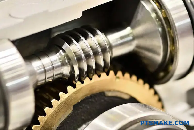
A worm drive’s action is simple yet powerful. Imagine a screw turning against a gear. This is the core principle. The threads of the screw, or "worm," mesh with the teeth of the gear.
The Screw and Gear Interaction
The worm’s rotation forces the gear to turn. Unlike typical gears that roll against each other, the worm’s thread slides across the gear’s teeth. This is the defining mechanical action.
Sliding Contact vs. Rolling Contact
This sliding motion is crucial. It dictates nearly every characteristic of the drive. The dominance of sliding over rolling contact is key.
| Contact Type | Primary Motion | Key Characteristic |
|---|---|---|
| Sliding | Surfaces rub | High Friction |
| Rolling | Surfaces roll | Low Friction |
This distinction is fundamental to understanding worm drives.
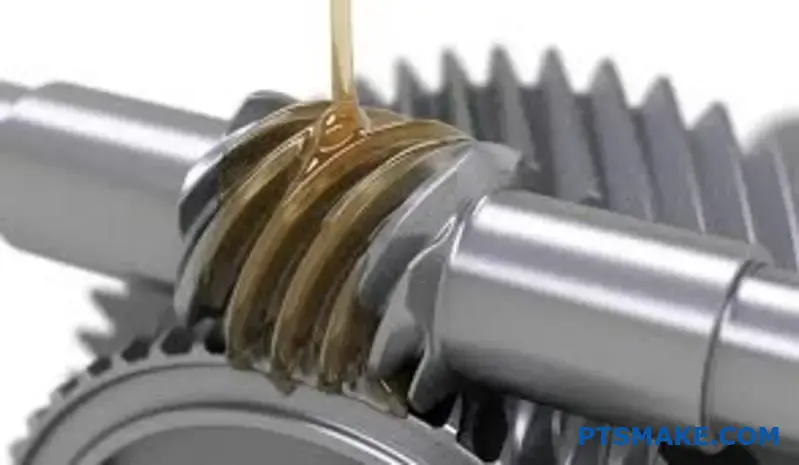
This fundamental sliding action has major consequences. The constant rubbing between the worm thread and the gear tooth creates significant friction. This is a primary trade-off in any worm and worm wheel design.
Friction and Its Byproducts
High friction means lower efficiency compared to other gear types. A lot of input energy is lost as heat. This often requires robust lubrication and sometimes cooling systems, especially in high-power applications we handle at PTSMAKE. This heat must be managed.
Achieving High Reduction Ratios
However, this sliding action enables incredible gear reduction ratios from a single stage. One full rotation of the worm might only advance the gear by a single tooth. This is how compact packages achieve ratios of 50:1 or even 100:1. The specific helical angle1 of the worm thread is a critical design factor here.
The Relationship Between Action and Performance
The drive’s performance is directly tied to this sliding interaction. Understanding this helps in selecting the right materials and design for optimal life and efficiency.
| Feature | Cause | Consequence |
|---|---|---|
| High Friction | Sliding Contact | Heat Generation, Lower Efficiency |
| High Reduction | Screw Action | Compact Size, High Torque |
| Self-Locking | High Friction & Angle | Inability to Back-drive |
This interplay defines the system’s core value in many applications.
The worm drive’s fundamental action is a screw’s thread sliding against a gear’s tooth. This high-friction, sliding motion is responsible for both its high reduction ratios and its inherent inefficiency, making it a specialized but highly effective mechanical component.
What defines the worm’s lead angle and its critical role?
The lead angle is more than just a measurement. It’s the heart of a worm gear’s performance. It dictates how efficiently the system runs.
It also determines if the mechanism can "self-lock." This means the worm wheel cannot drive the worm.
Think of it as a fundamental design choice. You are trading efficiency for control. This decision impacts the entire machine’s function.
| Lead Angle | Key Characteristic | Common Use Case |
|---|---|---|
| Small | Self-locking, Lower Efficiency | Lifting, Hoisting |
| Large | High Efficiency, Non-locking | Continuous Power Transmission |
The Trade-Off: Efficiency vs. Self-Locking
The lead angle has an inverse relationship with self-locking. Understanding this is crucial in worm and worm wheel design. A smaller lead angle creates more friction. This friction prevents the worm wheel from back-driving the worm.
This self-locking feature is invaluable for applications like hoists or jacks. It provides a built-in safety brake. However, this increased friction means lower efficiency. More energy is lost as heat.
Conversely, a larger lead angle reduces friction. This results in smoother operation and higher efficiency. Power is transmitted with minimal loss. These systems are ideal for continuous motion applications. But, they lose the self-locking benefit. The coefficient of friction2 between the materials becomes less of a factor in preventing back-driving.
At PTSMAKE, we help clients navigate this. We analyze the application’s needs to find the perfect balance.
Comparing Lead Angle Effects
| Feature | Low Lead Angle (< 5°) | High Lead Angle (> 10°) |
|---|---|---|
| Efficiency | Lower (30-50%) | Higher (50-90%+) |
| Self-Locking | Yes | No |
| Heat Generation | High | Low |
| Primary Goal | Positional Holding | Power Transmission |
The Critical Role in Application Design
Choosing the right lead angle is a critical step. It’s not just about a single component. It affects the entire system’s reliability and performance. A poor choice can lead to inefficiency or failure.
For example, using a high-efficiency gear in a lifting application would be dangerous. It could fail without a separate braking system.
The lead angle is a core parameter. It defines the fundamental behavior of the worm gear set.
In short, the worm’s lead angle presents a clear trade-off. You must choose between high operational efficiency or the inherent safety of self-locking. This decision is fundamental to successful worm gear system design and cannot be overlooked.
What are the essential geometric parameters of a worm gear pair?
Understanding a worm gear pair begins with its fundamental geometric parameters. These values are not just numbers on a spec sheet. They are the blueprint for the entire system.
These parameters directly control the gear’s performance. They affect the final speed ratio, torque capacity, and even the physical size. Getting them right is essential for any successful application.
At PTSMAKE, precision starts with these core definitions.
| Parameter | Primary Role |
|---|---|
| Number of Starts | Influences speed and efficiency |
| Number of Teeth | Sets the gear reduction ratio |
| Module / Pitch | Defines tooth size and strength |
| Center Distance | Determines the assembly layout |
| Pressure Angle | Affects force transmission and contact |
Let’s break down how these parameters work together in a practical sense. The interplay between them defines the final design and is a core part of effective Worm and Worm Wheel Design.
Number of Starts and Teeth
The gear ratio is simply the number of teeth on the wheel divided by the number of starts on the worm. A 60-tooth wheel with a two-start worm gives a 30:1 ratio. This is often the first parameter determined in a design process.
Module or Diametral Pitch
The module dictates the size of the gear teeth. A larger module results in bigger, stronger teeth that can handle more torque. However, this also increases the overall size of both the worm and the wheel, which might not fit within the design constraints.
Center Distance
This is the physical distance between the centerline of the worm and the centerline of the worm wheel. It is a critical dimension, often fixed by the housing design. All other parameters must be calculated to match this specific distance precisely.
Angles of Engagement
The pressure angle dictates how forces are transmitted between the teeth. The lead angle3 of the worm is equally important, as it must align with the wheel’s helix for smooth operation. Optimizing these angles is key to maximizing efficiency and minimizing wear.
| Parameter Impact | Performance Consequence |
|---|---|
| Ratio (Starts vs. Teeth) | Governs output speed and torque |
| Module | Directly affects strength and physical size |
| Center Distance | A primary physical constraint for the gearbox |
| Pressure & Lead Angles | Influences efficiency, noise, and operational smoothness |
In summary, the essential geometric parameters of a worm gear are a set of interconnected variables. A change in one parameter, like the number of starts to alter speed, requires adjustments to others to maintain proper function and fit within the designated space.
What is the principle of self-locking in worm wheel design?
Self-locking in a worm and worm wheel design is a fascinating and critical feature. It all comes down to a simple battle between geometry and friction. Think of it as a one-way gate for power.
The Role of Angles
The system’s behavior is dictated by two key angles: the lead angle and the friction angle. When friction wins, the system locks. This prevents the worm wheel from driving the worm backward. It’s a purely mechanical safety feature.
| Angle Type | Description | Role in Self-Locking |
|---|---|---|
| Lead Angle (λ) | The angle of the worm’s thread. | Represents the driving geometry. |
| Friction Angle (φ) | Determined by the materials’ friction. | Represents the resisting force. |
This principle is fundamental to creating safe and reliable gear systems for specific applications.
A Deeper Look: The Physics of Locking
Self-locking occurs when the friction angle is greater than the lead angle. This simple rule has profound implications. The friction angle itself is derived from the Coefficient of Static Friction4 between the mating surfaces of the worm and the wheel.
When the worm wheel attempts to drive the worm, the force it applies is mostly resisted by friction. If the lead angle is too shallow (smaller than the friction angle), the force component trying to rotate the worm is not strong enough to overcome the frictional force. The system simply jams, or "locks."
Designing for Safety
At PTSMAKE, we often leverage this principle for safety-critical applications. For devices like lifts or jacks, you cannot have the load back-drive the motor if power fails. A self-locking worm and worm wheel design is the perfect solution.
Here’s the condition broken down:
| Condition | Result | Can the Wheel Drive the Worm? |
|---|---|---|
| Friction Angle > Lead Angle | Self-Locking | No |
| Friction Angle < Lead Angle | Non-Locking (Back-drivable) | Yes |
Choosing the right materials and lubricants is key. Based on our tests, pairing a steel worm with a bronze wheel offers a predictable friction level, making it easier to design for reliable self-locking. This is a core aspect of our Worm and Worm Wheel Design process.
Self-locking is achieved when the friction angle exceeds the lead angle. This mechanical property prevents the worm wheel from back-driving the worm, making it a crucial safety feature in applications like hoists and jacks where load reversal must be prevented.
What are the non-negotiable material properties for worms and wheels?
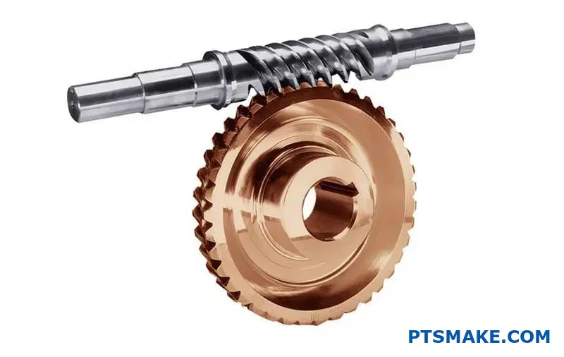
The performance of a worm gear set hinges on a critical contrast. The worm and the wheel must have different material properties.
This isn’t an accident; it’s by design. The worm is always the harder component. The wheel is intentionally made from a softer, more compliant material.
This fundamental difference manages the intense sliding friction. It ensures the system operates smoothly and lasts longer. Understanding this contrast is key to successful worm and worm wheel design.
| Component | Key Property | Common Material |
|---|---|---|
| Worm | Hardness & Smoothness | Hardened Steel |
| Wheel | Conformability & Low Friction | Bronze |
To manage the high sliding contact, the worm and wheel act as a specialized team. Each part has a distinct role defined by its material. It’s a classic example of smart engineering where materials are chosen to work together, not against each other.
The Worm: Hard and Smooth
The worm’s job is to endure constant, high-pressure sliding. For this, it needs exceptional hardness. Hardened steel is a common choice because it resists wear effectively.
A hard surface alone is not enough. The worm must also be ground and polished to a very smooth finish. This minimizes friction, which in turn reduces heat buildup and improves overall efficiency. A rough worm would quickly destroy the wheel.
The Wheel: Compliant and Self-Lubricating
The wheel needs a different set of properties. It is designed to be the softer part of the pair. Materials like bronze or certain polymers are ideal.
This softness allows the wheel to "wear in" and conform to the worm’s profile. This process increases the contact area, distributing the load more evenly. It also acts as a failsafe; the less expensive wheel is meant to wear out first, an example of sacrificial wear5. Bronze also offers excellent low-friction properties when running against steel, reducing the need for constant lubrication.
At PTSMAKE, we guide clients in selecting this material pairing to optimize the longevity of their assemblies.
The material contrast in a worm drive is non-negotiable. A hard, smooth worm ensures durability against sliding forces. A softer, low-friction wheel conforms to the worm and wears predictably, protecting the entire system and ensuring smooth, efficient power transmission.
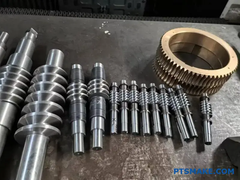
What is the difference between single and multi-start worms?
The real difference isn’t just counting threads. It’s about function and performance. A multi-start worm changes the entire dynamic of the gear set.
It increases the lead angle of the worm. This single change has a ripple effect. It directly boosts speed and efficiency.
However, this comes at a cost. You get a lower gear ratio. The self-locking ability also decreases significantly.
The choice depends on your application’s priority.
| Feature | Single-Start Worm | Multi-Start Worm |
|---|---|---|
| Lead Angle | Small | Large |
| Speed | Lower | Higher |
| Efficiency | Lower | Higher |
| Gear Ratio | High | Low |

Diving Deeper into Functional Trade-Offs
Choosing the right worm involves balancing competing factors. A larger lead angle in a multi-start worm means less sliding and more rolling contact. This is key to its higher efficiency.
In our work at PTSMAKE, we’ve seen this impact kinematic efficiency6 firsthand. Better efficiency translates to less wasted energy as heat. This can be critical in continuous-duty applications.
The trade-off is control. A single-start worm provides a very high gear ratio. This means precise, slow movement and high torque multiplication. It often has a natural self-locking tendency, which is great for holding loads.
A multi-start worm sacrifices this. The steeper angle makes it easier for the worm wheel to back-drive the worm. This is a crucial point in proper Worm and Worm Wheel Design. You must decide if you need speed or holding power.
Application-Driven Choices
| Application Need | Recommended Worm Type | Rationale |
|---|---|---|
| Hoists, Lifts | Single-Start | High gear ratio and self-locking are critical for safety. |
| Conveyor Systems | Multi-Start | Higher speed and efficiency are needed for throughput. |
| Indexing Tables | Single-Start | High precision and holding position are the main goals. |
| High-Speed Reducers | Multi-Start | The focus is on efficient speed reduction, not locking. |
Choosing between single and multi-start worms is a critical design decision. Multi-start worms offer speed and efficiency, while single-start worms provide high gear reduction and self-locking capabilities. The best choice is always dictated by the application’s specific functional needs.
What are the fundamental functions of lubrication in worm drives?
Lubrication in worm drives is not just an add-on. It is a fundamental part of the system’s design. Its main job is to manage friction.
This intense friction happens between the sliding surfaces of the worm and the wheel. Neglecting lubrication leads to rapid failure.
The Three Pillars of Worm Drive Lubrication
Proper lubrication serves three essential functions. Each is vital for performance and durability.
| Primary Function | Key Role in Worm Drives |
|---|---|
| Friction Reduction | Minimizes resistance between the worm and wheel. |
| Heat Dissipation | Cools the system by carrying heat away. |
| Surface Protection | Prevents wear, scoring, and chemical corrosion. |
Thinking of it as a core component is key.
The choice of lubricant is as critical as the gear geometry itself. The wrong fluid can cause more harm than good, leading to premature failure and costly downtime. It’s a decision we never take lightly in our projects at PTSMAKE.
An In-Depth Analysis of Lubrication’s Roles
Let’s break down why each function is so important. The unique sliding action of a worm drive makes lubrication a complex challenge. This isn’t like other gear sets.
Managing Friction and Heat
The constant sliding contact generates significant heat. A primary role of the lubricant is to create a film that separates the worm’s steel threads from the wheel’s softer bronze teeth. This minimizes direct metal-to-metal contact.
Simultaneously, the lubricant acts as a coolant. It absorbs thermal energy from the contact point and transfers it to the gearbox housing, where it can dissipate. Without this, temperatures would quickly rise, compromising material integrity. This is a core consideration in any robust Worm and Worm Wheel Design.
Protecting Surfaces from Damage
The lubricant also acts as a shield. It prevents scoring and wear on the gear surfaces. Additives in the oil create a protective chemical layer, which is essential under the high-pressure conditions often seen in worm drives. This state is known as boundary lubrication7.
| Failure Mode | Direct Cause |
|---|---|
| Pitting & Scoring | Lubricant film breakdown under pressure. |
| Overheating | Insufficient heat dissipation by the oil. |
| Corrosion | Moisture contamination and incorrect additives. |
It also protects against rust and corrosion, extending the operational life of the entire assembly.
Lubrication in worm drives is a multi-function component. It reduces friction, removes heat, and protects surfaces from wear and corrosion. Treating it as a critical design element, not an afterthought, is essential for reliable and long-lasting performance.
What are the primary classifications of worm gear types?
When selecting a worm gear, the choice often comes down to two main families. These are cylindrical and globoid worms.
The primary difference lies in the worm’s geometry. This directly influences the contact area with the worm wheel.
This single design choice affects performance, complexity, and overall cost. A proper worm and worm wheel design hinges on understanding this distinction.
| Type | Key Feature | Best For |
|---|---|---|
| Cylindrical | Straight worm profile | General applications |
| Globoid | Hourglass worm profile | High-load tasks |
Diving deeper into these two families reveals clear trade-offs. At PTSMAKE, we guide clients through this decision to match the design with their specific application needs. The choice is rarely about which is "better," but which is "right."
Cylindrical (Single-Enveloping) Worms
This is the most common type. The worm has a straight, cylindrical shape, similar to a screw thread.
Contact Area and Load Capacity
The contact between the worm threads and the wheel teeth occurs along a line. This limits the surface area for transferring power.
As a result, single-enveloping worm gears have a lower load capacity compared to their globoid counterparts. They are perfectly suited for moderate torque and general-purpose applications.
Complexity and Cost
Their straightforward geometry makes them easier and more affordable to manufacture. Standard tooling can be used, keeping production costs down. This makes them a cost-effective solution for many projects.
Globoid (Double-Enveloping) Worms
This design is more advanced. The worm has an hourglass or concave shape, allowing it to wrap partially around the worm wheel.
Contact Area and Load Capacity
This "enveloping" shape creates a much larger contact area. Instead of a line, the contact is a surface. The conjugate action8 is distributed over more teeth simultaneously.
This significantly increases the load-carrying capacity and shock resistance. Based on our tests, they can handle up to three times the load of a cylindrical worm of the same size.
Complexity and Cost
The complex geometry makes manufacturing difficult and expensive. It requires specialized machinery and precise alignment during assembly. Misalignment can quickly lead to failure, making the entire worm and worm wheel design more critical.
| Feature | Cylindrical (Single-Enveloping) | Globoid (Double-Enveloping) |
|---|---|---|
| Contact Pattern | Line contact | Area contact |
| Load Capacity | Standard | High |
| Efficiency | Good | Very High |
| Manufacturing Cost | Lower | Higher |
| Alignment Sensitivity | Less Sensitive | Highly Sensitive |
In summary, the decision balances performance against cost. Cylindrical worms are a practical, cost-effective choice for most applications. Globoid worms offer superior load capacity for heavy-duty tasks but demand higher manufacturing precision and budget.
What are the common failure modes in worm and wheel design?
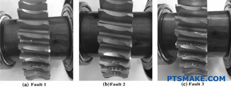
Understanding failure in worm and wheel design is the first step toward prevention. Failures aren’t random; they leave clues. Recognizing these signs helps us diagnose the root cause and improve future designs.
Different failures show up in unique ways. Identifying them correctly is crucial for effective troubleshooting. In my experience, most issues fall into a few common categories.
Below is a quick guide to what you might see.
| Failure Mode | Primary Visual Cue |
|---|---|
| Pitting | Small craters on the gear surface |
| Wear | Loss of material, smooth or rough |
| Bending/Breakage | Deformed or fractured worm threads |
| Scoring | Deep scratches or gouges along the sliding direction |
Each mode points to a specific underlying problem.
Linking Failures to Root Causes
Every failure tells a story about the gear set’s operating life. Tracing the failure back to its origin is essential. This is how we build more robust and reliable systems at PTSMAKE.
Pitting and Surface Fatigue
Pitting looks like small cavities on the gear tooth surface. It’s a classic sign of surface fatigue. This happens from high, repeated contact stresses that exceed the material’s endurance limit. The primary cause is often overloading or insufficient surface hardness.
Abrasive and Adhesive Wear
The softer bronze wheel is particularly prone to wear. Abrasive wear comes from hard particles in the lubricant. These contaminants grind away the wheel material. Adhesive wear occurs when lubricant fails, causing metal-to-metal contact and material transfer.
Bending and Breakage
A bent or broken worm thread is a catastrophic failure. This is almost always caused by a sudden shock load or a severe overload condition. It indicates the forces on the system far exceeded the worm’s design strength.
Lubrication Failure and Scoring
Scoring9 is characterized by deep scratches along the direction of sliding. This is a direct result of lubrication breakdown. The oil film thins, allowing high points on the surfaces to weld together and then tear apart.
| Failure Mode | Likely Root Cause |
|---|---|
| Pitting | Overloading, material fatigue |
| Abrasive Wear | Contaminated lubricant |
| Adhesive Wear | Inadequate lubrication, high pressure |
| Bending/Breakage | Extreme shock load or overload |
| Scoring | Lubrication film breakdown due to heat/pressure |
Understanding these common failure modes is crucial. Each one, from pitting to breakage, points to a specific root cause. Identifying these causes, such as overload or poor lubrication, allows for effective redesign and prevention, ensuring better Worm and Worm Wheel Design performance.
How do material pairings structure the design selection process?
Choosing the right materials is crucial in design. This is especially true for worm and worm wheel design. The process isn’t random; it follows a clear path.
The Classic Starting Point
Most designs begin with a standard pairing. This is typically a case-hardened steel worm with a phosphor bronze wheel. This combination is known for its reliability and performance under demanding conditions. It offers a great balance of strength and low friction.
A Decision-Making Framework
However, one size does not fit all. Your specific application dictates the best choice. We use a decision tree to guide this selection. It helps weigh factors like load, environment, and budget.
| Component | Standard Material | Key Benefit |
|---|---|---|
| Worm | Case-Hardened Steel | High Strength & Wear Resistance |
| Worm Wheel | Phosphor Bronze | Low Friction & Good Conformability |
This table shows the default choice. Now, let’s explore how the decision path can change based on project needs.
A Practical Decision Tree
A decision tree simplifies complex choices. It starts with the most critical question and branches out. For a worm and worm wheel design, the primary factor is almost always the operational load.
High-Load Applications
For high-torque and continuous use, the steel and bronze pairing is unmatched. The dissimilar metals have excellent tribological properties10. This pairing minimizes friction and galling, ensuring a long service life. In past projects at PTSMAKE, this has proven to be the most durable option.
Low-Load or Intermittent Use
What if the load is light? Or the device runs infrequently? Here, a cast iron worm wheel becomes a viable alternative. It significantly reduces material cost. However, it comes with higher friction and faster wear compared to bronze. This is a trade-off we help clients evaluate.
Special Environmental Factors
Consider a gear used in food processing. It requires corrosion resistance. In this case, stainless steel for both components is the best choice. While more expensive, it meets strict hygiene and durability standards.
| Wheel Material | Load Capacity | Cost Factor | Corrosion Resistance |
|---|---|---|---|
| Phosphor Bronze | High | High | Good |
| Cast Iron | Low to Medium | Low | Poor |
| Stainless Steel | High | Very High | Excellent |
This framework ensures the final material choice is a perfect fit for its intended function and environment.
Selecting materials for a worm and worm wheel design is a structured process. Starting with the standard steel-bronze pair, the decision tree branches based on load, cost, and environment to find the optimal solution for your specific application.
What are the standard mounting arrangements and their trade-offs?
Choosing how to mount your worm gear is a key design step. It is about more than just making it fit inside a machine.
The orientation directly impacts the system’s performance and lifespan. We generally consider three common setups.
Each arrangement comes with its own set of advantages and disadvantages. This affects lubrication, heat, and how forces act on the bearings. Understanding these is crucial for a reliable Worm and Worm Wheel Design.
Common Mounting Orientations
| Mounting Orientation | Primary Consideration |
|---|---|
| Worm Below Wheel | Optimal Lubrication |
| Worm Above Wheel | High-Speed Operation |
| Horizontal Axis | Balanced Performance |
This decision sets the stage for the gearbox’s long-term health.
A Deeper Look at Each Arrangement
Each mounting style creates a unique operating environment. Your choice is always a balance of trade-offs based on the application’s specific needs.
Worm Below the Wheel
This is often the best setup for lubrication. The worm is fully submerged in an oil bath. This ensures constant oil contact, minimizing wear, especially at low to medium speeds.
The main drawback is heat buildup. The worm constantly churning the oil generates extra friction and heat, which can be an issue.
Worm Above the Wheel
For high-speed jobs, this is usually preferred. Less oil is churned, meaning the system runs cooler and more efficiently.
However, lubrication can be a challenge. You must carefully manage the oil level to ensure splash lubrication reaches the worm and its bearings.
Horizontal Worm Axis
This is a great compromise and a solid general-purpose choice. It offers good lubrication without the excessive heat from churning.
Bearing loads are also more evenly distributed. In our past projects at PTSMAKE, we find this a reliable starting point. Achieving proper hydrodynamic lubrication11 is key in all setups, but this one presents a good balance.
Summary of Trade-Offs
| Arrangement | Lubrication | Heat Dissipation | Bearing Load | Best For |
|---|---|---|---|---|
| Worm Below | Excellent | Fair | Uneven | Low-to-mid speeds |
| Worm Above | Fair | Excellent | More even | High speeds |
| Horizontal Axis | Good | Good | Balanced | General purpose |
Your mounting choice is a critical engineering decision. It directly impacts lubrication effectiveness, heat management, and the ultimate lifespan of your bearings. It goes far beyond simple physical placement and defines the system’s long-term reliability and performance.
How do you calculate the primary forces on the worm and wheel?
Calculating forces in a worm gear set is not just academic. It’s the foundation for a reliable mechanical system. Miss this step, and you risk failure.
We focus on three primary forces. Each one plays a distinct role in the gear’s operation and longevity. Proper Worm and Worm Wheel Design depends on this.
Here is a quick breakdown:
| Force Type | Description |
|---|---|
| Tangential Force | The force that transmits power. |
| Radial Force | The force that pushes the gears apart. |
| Axial Force | The thrust force along the shaft’s axis. |
Understanding these forces is the first step. It allows you to design shafts and select bearings that will last.
A Deeper Look at Force Calculation
To correctly size components, you need to calculate the magnitude of these forces on both the worm and the wheel. The inputs are simple: torque, speed, and gear geometry.
Forces Acting on the Worm
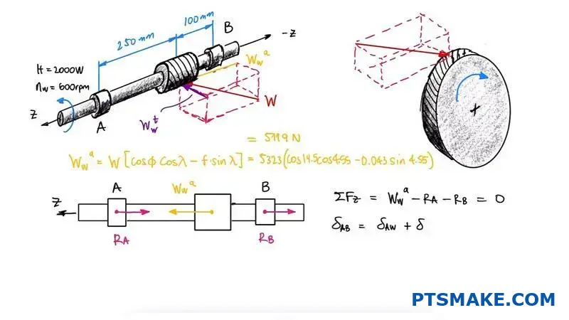
The worm experiences a tangential force (Wt), a radial force (Wr), and an axial force (Wa). The tangential force is determined from the input torque. The other two forces are then calculated based on the gear’s geometry. This includes the lead angle and the normal pressure angle12.
In our work at PTSMAKE, we’ve found that accurately calculating the worm’s axial force is particularly critical. This force is often substantial and directly dictates the type of thrust bearing required for the application.
Forces Acting on the Worm Wheel
The forces on the worm wheel are directly related to the forces on the worm, but their orientation is different. The forces are equal in magnitude but opposite in direction.
| Force on Worm | Corresponding Force on Wheel |
|---|---|
| Tangential Force (Wt) | Axial Force (Wa_wheel) |
| Axial Force (Wa) | Tangential Force (Wt_wheel) |
| Radial Force (Wr) | Radial Force (Wr_wheel) |
This relationship is key. The tangential force on the wheel (Wt_wheel) is what produces the output torque. The axial force on the wheel dictates its bearing requirements.
Calculating these tangential, radial, and axial forces is a non-negotiable first step. This essential data informs the selection of appropriate bearings and the design of robust shafts, ensuring the mechanical integrity and reliability of the entire gear system.
How do you design a shaft for the worm and worm wheel?
Designing the shaft is a critical part of any Worm and Worm Wheel Design. It’s more than just picking a diameter. We must analyze all forces acting on it.
This process involves calculating bending moments and torques. These forces come directly from the gear interaction.
Our main goal is to find the right shaft diameter. It must be strong enough to resist fatigue. It also needs to limit deflection for smooth gear meshing.
Key Design Steps
| Step | Description |
|---|---|
| 1 | Analyze Forces |
| 2 | Calculate Moments & Torques |
| 3 | Select Material |
| 4 | Determine Diameter |
| 5 | Check for Deflection |
This structured approach ensures a reliable and long-lasting assembly.
After calculating the forces in the previous step, we map them onto the shafts. This helps us visualize the bending moments and torques along the entire length. This is a fundamental step.
We create shear and moment diagrams for both the worm and wheel shafts. These diagrams pinpoint the locations of maximum stress. This is where failure is most likely to occur. At PTSMAKE, we use software to ensure accuracy.
Shafts experience both bending and torsional stress. We combine these to find the equivalent stress. This is crucial for selecting the right material and diameter. Material choice directly impacts strength and durability.
A key concern is fatigue failure13. Since shafts rotate, the stress cycles constantly. This repeated loading can cause cracks to form and grow over time, even if the stress is below the material’s ultimate strength.
Shaft Design Considerations
| Factor | Importance | Reason |
|---|---|---|
| Material Strength | High | Must withstand combined stresses. |
| Stress Concentrators | High | Keyways and shoulders create weak points. |
| Deflection Limit | High | Ensures proper gear tooth contact. |
| Bearing Location | High | Affects bending moments and stability. |
Finally, we check for deflection. Excessive shaft bending misaligns the gears. This leads to noise, increased wear, and eventual system failure. Our goal is to keep deflection within very tight, acceptable limits for proper meshing.
Proper shaft design is a detailed process. We analyze forces, determine moments, and calculate a diameter. This ensures the shaft resists fatigue and minimizes deflection for reliable gear meshing, a core principle we apply in our projects at PTSMAKE.
How does a duplex worm system achieve backlash control?
A duplex worm system is an advanced solution for eliminating backlash. It is essential in applications where precision is non-negotiable.
This mechanism uses a worm with two slightly different profiles. This allows for fine-tuning the gear mesh.
The Core Concept
The worm is effectively split into two sections. Each has a slightly different lead angle. This is the key to its adjustability. Axial movement changes the engagement, removing any play.
Why It Matters
In precision machinery, even tiny gaps can cause errors. This design ensures tight, accurate motion transfer.
| Feature | Standard Worm | Duplex Worm |
|---|---|---|
| Backlash | Fixed, inherent | Adjustable to near-zero |
| Complexity | Simple | More complex |
| Cost | Lower | Higher |
| Precision | Good | Exceptional |
This advanced approach to Worm and Worm Wheel Design offers superior control.
The Mechanics of Adjustment
A duplex worm gear system achieves backlash control through a unique design. The worm itself is constructed with two distinct lead profiles on its opposite tooth flanks.
One flank has a slightly larger lead than the other. This subtle difference is engineered into the worm during manufacturing. It is not a simple split but a sophisticated geometric variance.
Achieving Zero Backlash
To adjust backlash, the worm is moved axially relative to the worm wheel. As the worm shifts, the different lead profiles engage the wheel teeth at different points.
This axial movement effectively "thickens" the worm’s tooth profile at the point of contact. This pushes the worm wheel teeth from both sides, eliminating the gap between them and removing all play. This process allows for extremely fine and precise adjustments to achieve near-zero backlash. The helical angle14 plays a critical role in this adjustment process.
Applications in Precision Machinery
At PTSMAKE, we’ve integrated such systems into high-precision applications. They are vital for robotics, CNC machines, and astronomical telescopes. These fields demand exact positioning with no room for error.
| Industry | Application | Reason for Use |
|---|---|---|
| Robotics | Joint articulation | Smooth, precise movement |
| Aerospace | Actuator control | High reliability, zero play |
| Metrology | CMM machines | Extreme positional accuracy |
| Medical | Surgical robots | Flawless motion control |
The duplex system ensures the machine performs its task with the highest degree of accuracy and repeatability.
The duplex worm system uses a worm with dual lead profiles. Shifting the worm axially adjusts tooth engagement, effectively eliminating backlash. This design is critical for achieving the highest precision in advanced machinery.
How would you design a worm drive for a robotic joint?
Designing for a modern robotic joint is a true challenge. It’s not just about motion; it’s about extreme precision.
You need to achieve several conflicting goals at once. These include zero backlash for accuracy and high stiffness for quick responses.
Core Design Challenges
| Requirement | Impact on Performance |
|---|---|
| Zero Backlash | Enables precise positional control. |
| High Stiffness | Ensures immediate, responsive movement. |
| Low Inertia | Allows for rapid acceleration/deceleration. |
| Compactness | Fits within tight robotic joint spaces. |
This forces a synthesis of materials and geometry.
Parts2:
Parts3:
Let’s tackle these requirements one by one. The goal is to create a seamless, integrated system.
Achieving Zero Backlash
Eliminating backlash is critical for robotic accuracy. A simple gear set won’t do.
One effective method is using a Duplex Worm Gear15. This design features a worm with a variable pitch. It allows us to precisely adjust the mesh with the worm wheel, effectively removing any play. This is a common approach in past projects at PTSMAKE for high-precision applications.
Balancing Stiffness and Low Inertia
Stiffness ensures the robot arm doesn’t flex under load. Low inertia allows it to move quickly. These two are often at odds.
For the worm and worm wheel design, material selection is everything.
| Component | Optimal Material | Rationale |
|---|---|---|
| Worm | Hardened Steel (e.g., 4140) | High strength and wear resistance. |
| Worm Wheel | Phosphor Bronze | Excellent lubricity and durability. |
| Housing | 7075 Aluminum | High strength-to-weight ratio. |
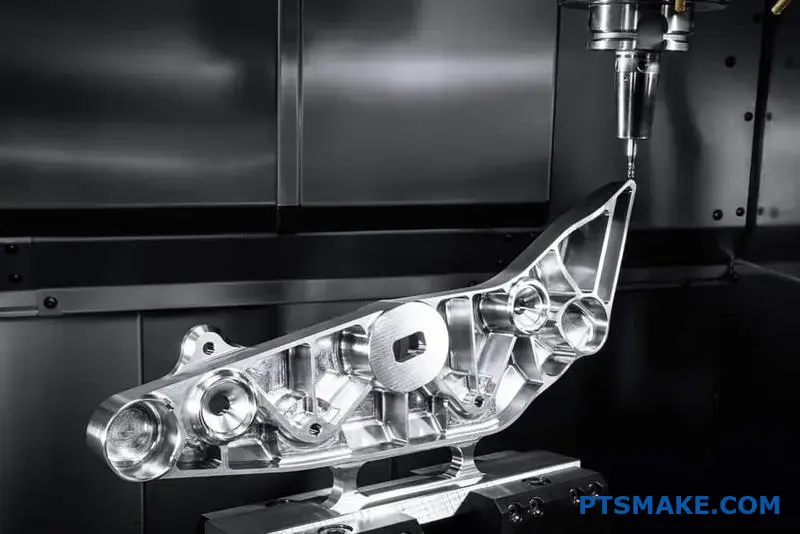
To further reduce inertia, we can design the worm with a hollow shaft. We use advanced CNC machining to create these complex, lightweight parts without compromising strength. This integration of design and manufacturing is key.
Parts4:
In conclusion, designing a robotic worm drive is an exercise in optimization. It demands a holistic approach, blending advanced gear geometry, strategic material selection, and tight system integration to satisfy the strict requirements for precision, responsiveness, and compactness.
Parts5:
Take Your Worm and Worm Wheel Design Further with PTSMAKE
Ready to turn high-precision worm and worm wheel design into production reality? Contact PTSMAKE for a fast, reliable, and detailed quotation—experience seamless communication, trusted quality, and on-time delivery for your next project. Send your inquiry today and let precision manufacturing empower your success!

Discover how this angle directly impacts the drive’s efficiency and self-locking capabilities. ↩
Discover how this key value directly impacts the self-locking capability and overall efficiency in gear systems. ↩
Click to learn how the lead angle is calculated and its role in optimizing worm gear efficiency. ↩
Explore how this material property is essential for predicting and ensuring the self-locking behavior in your designs. ↩
Learn how this design principle extends the operational life of mechanical systems. ↩
Understand how motion and forces are transmitted in gear systems to improve your designs. ↩
Discover how this thin film prevents gear failure under extreme pressure and load. ↩
Understand how this principle ensures smooth and constant power transmission in gearing. ↩
Learn how lubrication failure causes severe gear damage and what steps you can take to prevent it. ↩
Understand how surface interaction affects friction, wear, and the lifespan of your gear components. ↩
Click to understand how a fluid film reduces friction and wear in your gearing system. ↩
Learn how the pressure angle affects gear performance and force distribution in our detailed guide. ↩
Discover how repeated stress below the yield point can lead to material failure over time. ↩
Understand how this angle is fundamental to gear meshing and backlash control. ↩
Explore how this advanced gearing technology eliminates play for ultimate precision control. ↩