Designing a heat sink for high-power electronics? You’re probably struggling with thermal interface resistance and wondering if your current solution can handle the heat load without becoming a bottleneck that destroys performance.
Skived pin heat sinks offer superior thermal performance through monolithic construction, eliminating thermal interface resistance between fins and base while providing exceptional design flexibility for high-power applications across electronics, automotive, and aerospace industries.
After working with thermal management solutions at PTSMAKE, I’ve seen how the wrong heat sink choice can derail entire projects. This guide covers everything from material selection to performance optimization, helping you make informed decisions that prevent costly redesigns and ensure your thermal management meets specifications.
Why is monolithic construction thermally superior?
When managing heat, every detail matters. The connection between a heat sink’s base and its fins is a critical point. A single, solid piece of metal always outperforms assembled parts.
The Problem with Joints
Any joint, no matter how perfect, creates a barrier. This barrier slows down heat transfer. Monolithic designs simply don’t have this problem.
Performance Comparison
| Construction Type | Thermal Barrier | Heat Transfer Efficiency |
|---|---|---|
| Monolithic | None | Maximum |
| Assembled (e.g., bonded) | Yes | Reduced |
This simple difference is why monolithic construction is superior.
In thermal management, we constantly battle a hidden enemy. This enemy is called thermal interface resistance1. It occurs at the boundary between two contacting surfaces.
Even perfectly smooth surfaces have microscopic air gaps. These gaps act like insulation, trapping heat and preventing it from moving efficiently.
Eliminating the Barrier
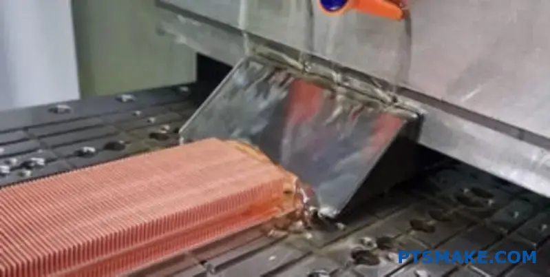
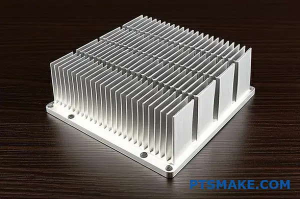
This is where monolithic construction shines. Techniques like skiving create a heat sink from a single block of material. At PTSMAKE, we often recommend this for demanding applications.
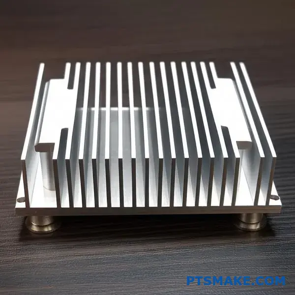
A Skived pin heat sink, for example, has no joint between the base and the fins. They are one continuous piece of metal.
Heat Flow: Monolithic vs. Assembled
| Feature | Monolithic (Skived) | Assembled (Bonded/Soldered) |
|---|---|---|
| Base-to-Fin Joint | None (Integral) | Present (e.g., Epoxy, Solder) |
| Interface Gaps | Zero | Microscopic air/filler gaps |
| Heat Path | Uninterrupted | Obstructed |
| Thermal Performance | Superior | Compromised |
This uninterrupted path allows heat to flow from the base to the fins with almost zero resistance. This leads to the most effective cooling possible.
Monolithic designs, such as those used in skived heat sinks, eliminate thermal interface resistance by removing the joint between the base and fins. This creates an unbroken path for heat, ensuring maximum thermal transfer and superior cooling performance.
How does pin density influence thermal performance?
Pin density is a classic trade-off. At first, adding more pins seems like a great idea.
More pins mean more surface area. This provides a larger space for heat to escape into the surrounding air.
However, cramming pins too close together can backfire. It increases resistance to airflow. This can choke the system, reducing cooling efficiency.
Finding the right balance is key to effective thermal design.
| Pin Density | Surface Area | Airflow Resistance |
|---|---|---|
| Low | Lower | Low |
| High | Higher | High |
| Optimal | Balanced | Balanced |
The Search for Optimal Density
The "perfect" pin density isn’t a universal number. It heavily depends on the specific cooling environment, especially the airflow conditions.
Forced vs. Natural Convection
In a forced convection system with powerful fans, you can use a higher pin density. The strong airflow can overcome the increased resistance, taking full advantage of the larger surface area.
For natural convection setups, where air moves without fans, a lower density is often better. This approach minimizes obstruction, allowing air to circulate more freely between the pins.
In past projects, we’ve found that modeling airflow is crucial. This is particularly true for a skived pin heat sink, where fins are manufactured with high precision. Understanding the system’s overall thermal resistance2 is the goal.
| Airflow Condition | Fan Speed | Recommended Pin Density |
|---|---|---|
| Natural Convection | None | Low |
| Forced Convection | Low | Medium |
| Forced Convection | High | High |
Material and Design Impact
The material of the heat sink, like aluminum or copper, also plays a role. Copper’s higher thermal conductivity might allow for a slightly different density optimization compared to aluminum under the same conditions. At PTSMAKE, we work with clients to simulate these variables for the best outcome.
The goal is to maximize heat dissipation without creating a significant blockage that starves the system of cool air. This balance point is the optimal pin density.
Pin density involves a critical trade-off. Higher density increases surface area but can restrict airflow. The optimal density depends entirely on the system’s specific airflow conditions, balancing surface area with air pressure drop to achieve maximum thermal performance.
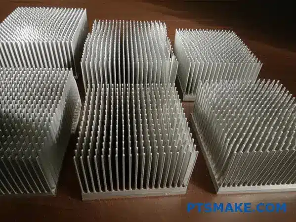
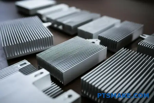
What are the primary advantages of skived pin fins?
Skived pin fins offer incredible thermal performance. This is mainly because they are made from a single block of material.
There’s no thermal resistance from a solder or epoxy joint. This creates a highly efficient path for heat to escape.
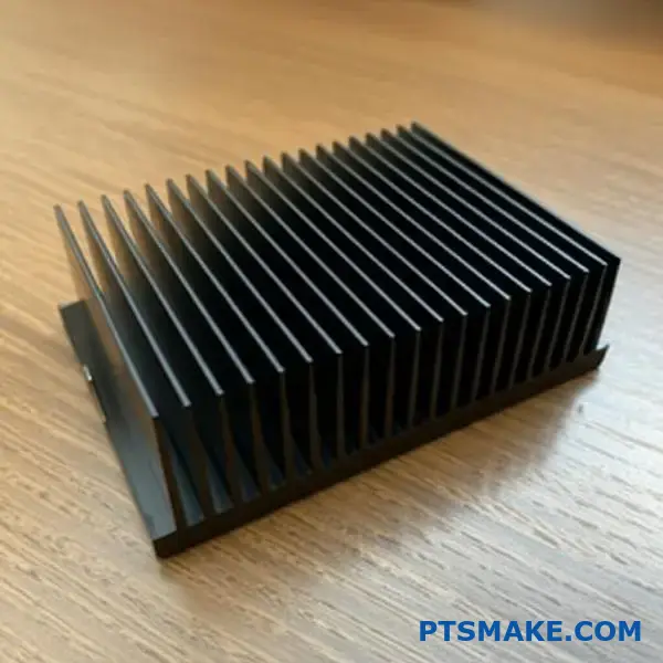
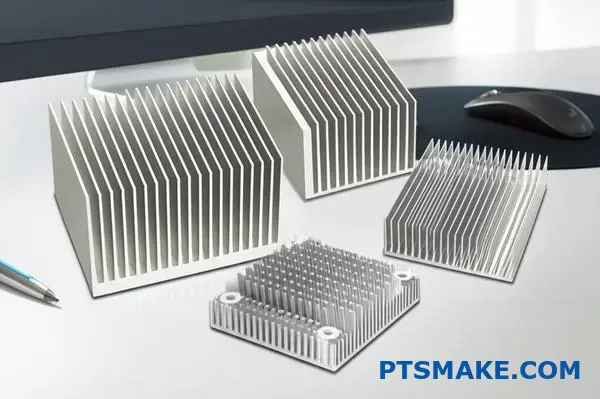
The process allows for very thin, densely packed fins. This maximizes the surface area for heat dissipation. It’s a key reason we recommend them for compact electronics.
Below is a quick overview of the main benefits.
| Advantage | Impact on Performance |
|---|---|
| High Fin Density | Increases surface area for cooling |
| Thin Fin Capability | Reduces weight and material usage |
| Excellent Conductivity | No thermal interface loss |
| High Aspect Ratio | Maximizes cooling in a small footprint |
This combination makes a skived pin heat sink a top choice.
Breaking Down the Benefits
Let’s look closer at why these features matter. The manufacturing process itself is the source of these advantages. Skiving carves fins from a solid block, not joining them.
This single-piece construction is a game-changer. It ensures the heat path from the base to the fin tips is unbroken. The result is superior thermal conductivity compared to bonded or stamped fin designs.
High Aspect Ratio and Density
A high aspect ratio means the fins are much taller than they are thick. This design maximizes the cooling surface without increasing the heatsink’s footprint. It’s crucial for devices with limited space.
In our past projects at PTSMAKE, we’ve seen how this directly improves cooling. More fins can be packed into the same area. But this requires careful design to manage airflow. The balance is crucial for maintaining optimal interstitial velocity3 and achieving efficient cooling.
| Fin Density | Airflow Resistance | Typical Application |
|---|---|---|
| Low | Low | Natural Convection |
| Medium | Medium | Low-speed fans |
| High | High | High-pressure blowers |
Design Flexibility
Skiving technology gives us at PTSMAKE great design freedom. We can adjust fin height, thickness, and pitch. This allows us to create a custom skived pin heat sink perfectly matched to your specific thermal needs and airflow conditions.
Skived pin fins deliver superior thermal management. Their single-piece construction, high fin density, and design flexibility provide a significant cooling advantage in a compact form factor, making them ideal for high-performance applications.
What are the inherent limitations of the skiving process?
The skiving process is highly effective. Yet, it has clear physical boundaries. These limits define what is possible in manufacturing.
Engineers must understand these constraints early. This ensures their designs are feasible from the start. It saves time and avoids costly redesigns. Key factors include material block size and fin geometry.
Maximum Block and Fin Dimensions
The size of the skiving machine dictates the maximum part size. The tool’s strength and material properties limit fin dimensions. Ignoring these can lead to production failures.
Here are some typical constraints we see.
| Constraint | Typical Maximum/Minimum | Reason |
|---|---|---|
| Block Width | ~500 mm | Machine bed size |
| Fin Height | ~120 mm | Tool stability |
| Fin Thickness | ~0.1 mm | Material integrity |
These are general guidelines. They can change based on the material and specific machine used.
Design Feasibility and Practical Constraints
Understanding these limitations is crucial for design for manufacturability (DFM). A design might look great in CAD software. But it must be physically producible. In our projects at PTSMAKE, we often guide clients on these practical aspects.
Material Block Size
The raw material block has a maximum size. This is limited by our machinery’s capacity. If your heat sink design is larger than the machine’s work envelope, skiving isn’t the right choice. You might need to consider other methods.
Fin Height-to-Thickness Ratio
This ratio is very important. You can’t have extremely tall and thin fins. As the fin gets taller, the skiving tool extends further from its support. This extension can lead to issues like tool deflection4, affecting final part accuracy. A higher ratio increases the risk of fins bending or breaking during the process.
This is especially true for a skived pin heat sink. Each pin must be stable.
| Feature | Designer’s Wish | Manufacturing Reality |
|---|---|---|
| Fin Height | 150 mm | Often limited to <120 mm |
| Fin Thickness | 0.05 mm | Rarely feasible below 0.1 mm |
| Fin Pitch | Very dense | Limited by tool width |
We always advise balancing thermal performance with these manufacturing constraints for a successful outcome.
Practical constraints like block size, fin height, and fin thickness are not suggestions; they are rules set by physics and machine capabilities. Successful design for skiving requires respecting these limits from the beginning to ensure a producible and effective final product.
How does fin thickness affect heat transfer efficiency?
Fin thickness is not a simple "more is better" equation. It is a careful balancing act. The core concept to understand here is ‘fin efficiency.’ This measures how effectively a fin transfers heat.
A thicker fin conducts heat better along its length. But it also takes up more space. Thinner fins allow for more fins in the same area. This increases the total surface for heat to escape. Finding the ideal balance is crucial.
Fin Thickness Trade-Offs
| Feature | Thicker Fins | Thinner Fins |
|---|---|---|
| Conduction | Higher | Lower |
| Fin Density | Lower | Higher |
| Surface Area | Potentially Lower | Potentially Higher |
| Weight | Heavier | Lighter |
The Physics Behind Fin Performance
To understand the balance, think of heat traveling from the base to the tip of a fin. This journey is key to its performance.
Heat’s Journey: Conduction
A fin’s job is to conduct heat away from the source. It then transfers that heat to the surrounding air. A thicker fin provides a wider path for heat. This means less resistance. The fin’s tip stays closer to the base temperature, making the entire surface effective.
In contrast, a thin fin has higher resistance. The tip becomes much cooler than the base. This reduces the heat transfer capability of the fin’s outer portion.
Density vs. Individual Performance
So, why not always use thick fins? Because space is limited. Thinner fins let us pack more surface area into a given volume. This is often seen in skived pin heat sink5 designs we produce at PTSMAKE.
More fins mean more total surface for convection. The goal is to find the point where adding more fins (and surface area) outweighs the reduced efficiency of each individual fin. In our past projects, we found this balance is different for every application. It depends on airflow, power output, and space constraints.
| Aspect | Impact of Thickness | Design Goal |
|---|---|---|
| Fin Efficiency | Thicker fins are more efficient individually. | Maximize heat transfer per fin. |
| Surface Area | Thinner fins allow for greater total area. | Maximize total heat dissipation. |
| Application | High heat flux may need thicker fins. | Find the optimal balance for the system. |
Fin thickness presents a fundamental trade-off. You must balance the superior heat conduction of thicker fins against the increased surface area offered by a denser array of thinner fins. The optimal solution is always tailored to the specific application’s thermal requirements.
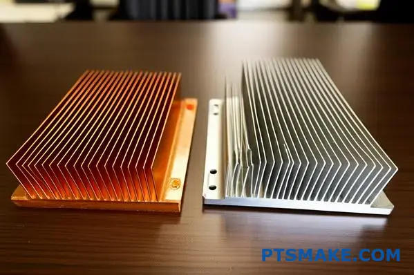
Why choose copper over aluminum for a skived heatsink?
The choice between copper and aluminum is a classic engineering trade-off. It’s all about balancing performance against practical constraints. Your application’s needs will dictate the right material.
Thermal Performance vs. Cost
Copper’s main advantage is its superior thermal conductivity. It transfers heat almost twice as effectively as aluminum. This makes it ideal for high-heat situations.
However, aluminum is lighter and more cost-effective. These factors are often critical in product design.
Here is a direct comparison:
| Feature | Copper | Aluminum |
|---|---|---|
| Thermal Conductivity | ~400 W/mK | ~205 W/mK |
| Density (Weight) | High | Low |
| Relative Cost | Higher | Lower |
This decision is fundamental for any skived heatsink design. You must weigh what matters most.
Matching Material to Application
In practical terms, this trade-off guides your material selection. We see this often in projects at PTSMAKE. The specific use case is everything.
High-Heat Environments
For high-power CPUs, GPUs, or power electronics, heat is the enemy. In these cases, copper is often the only choice. Its ability to quickly pull heat away from the source is essential. The higher cost is justified by performance. Copper’s lower thermal impedance6 ensures components stay within safe operating temperatures.
Weight and Budget-Driven Designs
Conversely, aluminum is perfect for weight-sensitive applications. Think of portable devices or aerospace components. It’s also the go-to for cost-sensitive consumer electronics. Its performance is more than adequate for many common thermal challenges. A skived pin heat sink made from aluminum offers a fantastic balance of performance and value.
This table shows typical application-material pairings:
| Application Type | Primary Concern | Recommended Material |
|---|---|---|
| Data Center Servers | Max Cooling | Copper |
| Consumer Laptops | Weight & Cost | Aluminum |
| LED Lighting | Cost-Effectiveness | Aluminum |
| Industrial Power Inverters | High Reliability | Copper |
Ultimately, understanding these differences helps you make a smarter, more efficient choice for your project.
Choosing between copper and aluminum for a skived heatsink depends on your specific needs. Copper offers unmatched thermal performance for demanding applications, while aluminum provides a lighter, more cost-effective solution for a wider range of uses. The decision hinges on this balance.
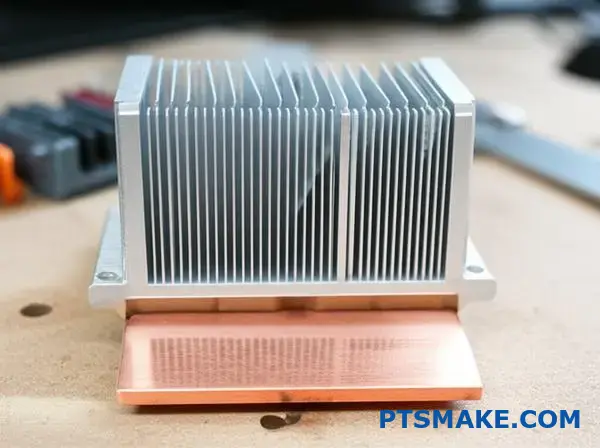
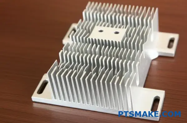
What is the role of the integral base?
The integral base is the foundation of the entire cooling system. Think of it as the primary heat spreader. Its main job is to collect heat from a source, like a CPU, and distribute it evenly.
This distribution is crucial for the rest of the heat sink to work effectively. Without a solid base, heat transfer becomes inefficient.
The First Point of Contact
The base makes direct contact with the heat source. Its design directly impacts how quickly heat moves away. This initial transfer is a critical step in the cooling process for any skived pin heat sink.
Importance of Uniform Spreading
A well-designed base ensures heat spreads out to all the skived pins. This maximizes the surface area available for dissipation.
| Base Property | Impact on Performance |
|---|---|
| Thickness | Affects spreading speed and uniformity |
| Material | Determines thermal conductivity |
| Flatness | Ensures optimal contact with the heat source |
This structure prevents hot spots and ensures the entire unit performs as intended. The base is more than just a mounting platform.
The base acts as the critical bridge between the heat source and the fins. Its physical characteristics, especially thickness and material integrity, dictate its performance. They are not minor details; they are fundamental to the heat sink’s function.
Optimizing Base Thickness
A base that is too thin cannot spread heat effectively. This can create localized hot spots, overwhelming the pins directly above the source.
Conversely, a base that is too thick can slow down the transfer of heat to the fins. In past projects with clients, finding this balance is key for optimal performance. We aim for the sweet spot where spreading is fast and uniform.
Ensuring Material Integrity
The material itself, typically copper or aluminum, must be pure. Voids, impurities, or inconsistencies within the metal can create barriers to heat flow.
These imperfections disrupt the uniform distribution of thermal energy. This is because any defect can significantly increase the thermal impedance7 of the material.
| Material Defect | Consequence |
|---|---|
| Air Voids | Poor conductor, traps heat |
| Impurities | Lower overall thermal conductivity |
| Inconsistent Density | Uneven heat spreading |
At PTSMAKE, we ensure our raw materials meet strict standards. This guarantees the integrity of the base and the reliable performance of the final skived pin heat sink. This commitment to quality prevents performance bottlenecks.
The integral base is the primary heat spreader. Its effectiveness depends entirely on its thickness and material integrity. These factors ensure uniform heat distribution from the source to the fins, which is crucial for overall cooling performance.
Skived Pin vs. Extruded: What are the key differences?
When choosing a heat sink, practical factors matter most. It’s not just about one being "better." It’s about which is right for your project’s specific needs.
A skived pin heat sink often wins for performance. Extruded sinks can be better for high-volume, lower-cost needs.
Here is a quick comparison table to help you decide. It covers the key selection criteria we look at in our projects at PTSMAKE.
| Feature | Skived Pin Heat Sink | Extruded Heat Sink |
|---|---|---|
| Fin Density | Very High | Moderate |
| Aspect Ratio | High | Low to Moderate |
| Thermal Performance | Excellent | Good |
| Tooling Cost (NRE) | None | High |
| Design Flexibility | High | Limited |
Deeper Dive into the Comparison
Let’s break down the table further. The differences become clear when you look at the manufacturing process and its results. Each method has unique strengths.
Fin Density and Performance
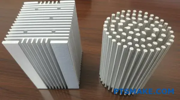
Skiving technology literally shaves fins from a solid block of metal. This allows for very thin, densely packed fins. More fins mean more surface area for heat dissipation.
This process enables a higher aspect ratio8, which is key for thermal efficiency. In contrast, extrusion pushes material through a die. This limits how thin and tall the fins can be.
Based on our tests, skived pin heat sinks can improve thermal performance by 10-20% over extruded counterparts in forced convection environments.
Tooling Costs vs. Unit Price
Tooling is a major factor. Extrusion requires a custom die, which creates a significant upfront Non-Recurring Engineering (NRE) cost. This makes it unsuitable for prototypes or small runs.
Skiving requires no specific tooling, so NRE is zero. This makes it perfect for rapid prototyping and low-to-mid volume production. While the per-unit cost might be higher, the overall project cost is often lower for smaller quantities.
Skived pin heat sinks excel in performance and flexibility with no tooling costs, making them ideal for prototypes and demanding applications. Extruded heat sinks are the cost-effective choice for high-volume production where thermal requirements are less critical.
When to choose skived over bonded fin heat sinks?
The choice often comes down to the thermal interface. This is the critical point where heat must travel from the heat sink base to the fins.
Understanding the Interface Difference
Bonded fins rely on an epoxy or solder to join the fins to the base. While effective, this joining material adds a layer of resistance. This can impede heat transfer.
A skived fin heat sink is made from one solid piece of metal. This monolithic design means there is no thermal joint between the base and fins.
| Feature | Bonded Fin Heat Sink | Skived Fin Heat Sink |
|---|---|---|
| Fin-to-Base Joint | Epoxy or Solder | None (Monolithic) |
| Interface Resistance | Present (Higher) | Negligible (Lower) |
For high-power applications, this seemingly small detail becomes a major performance factor.
The Impact of Interface Resistance
Let’s dig deeper into that bonded fin joint. The epoxy or solder is simply not as thermally conductive as the aluminum or copper base. This creates a bottleneck where heat struggles to cross efficiently from the base into the fins.
This bottleneck is quantified as thermal resistance9. A higher thermal resistance means the component will run hotter under the same load. It’s a crucial factor in thermal design.
High Power Density Applications
In devices with high power density, this added resistance is unacceptable. When a lot of heat is generated in a small space, even a tiny barrier can cause a significant and harmful temperature rise. This is where skived fins offer a clear advantage.
By being a single piece of metal, a skived fin heat sink completely eliminates this interface resistance. In past projects at PTSMAKE, we’ve seen this single factor lower operating temperatures by several degrees, directly boosting device reliability and lifespan.
| Power Density Level | Typical ΔT from Bonded Interface | ΔT from Skived Interface |
|---|---|---|
| Low | ~1-2°C | 0°C |
| Medium | ~3-5°C | 0°C |
| High | >7°C | 0°C |
Summary
The crucial difference is the thermal joint in bonded fins, which adds performance-killing resistance. Skived fins are monolithic, eliminating this bottleneck entirely. This makes them the clear choice for demanding, high-power applications where every degree of cooling counts.
How are skived pin designs categorized by airflow type?
The most critical factor in a skived pin heat sink design is airflow. This single element dictates the entire geometry of the part. Designs are split into two main categories. These are natural convection and forced convection.
Each category requires a fundamentally different approach to fin spacing and height. Choosing the wrong design for your airflow type will lead to poor thermal performance.
| Airflow Type | Fin Spacing | Fin Height |
|---|---|---|
| Natural Convection | Wide | Shorter |
| Forced Convection | Narrow (Dense) | Taller |
This choice is the foundation for effective cooling.
Natural Convection: Designing for Passive Air Movement
Natural convection relies on the principle that hot air rises. The heat sink warms the surrounding air, which then becomes less dense and moves upward. This pulls cooler air in from below.
For this to work, the fins must have wide spacing. This creates clear channels for air to move without significant resistance. If the fins are too close, they will trap air, stalling the cycle.
Key Design Features:
- Wider Pin Gaps: Allows for unrestricted, buoyancy-driven airflow.
- Shorter Pin Height: Reduces overall air resistance and weight.
Forced Convection: Maximizing Surface Area
Forced convection uses a fan or blower to move air across the heat sink. This active airflow is much more powerful and efficient at removing heat.
Because we are actively pushing air, we can make the fins much taller and closer together. This dramatically increases the surface area that contacts the moving air. The design goal is to disrupt the thermal boundary layer10 on each fin.
| Convection Type | Typical Application | Key Advantage |
|---|---|---|
| Natural | Silent PCs, Audio Amplifiers | No noise, no power needed |
| Forced | Servers, Power Supplies, LED Lighting | High-performance cooling |
At PTSMAKE, the first question we ask is always about your cooling environment. This ensures the part we machine is optimized for its real-world application.
The core distinction is simple: natural convection designs prioritize low air resistance, while forced convection designs maximize surface area. The right choice is entirely dependent on whether a fan is present, directly influencing the heat sink’s physical structure for optimal performance.
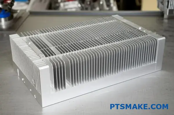
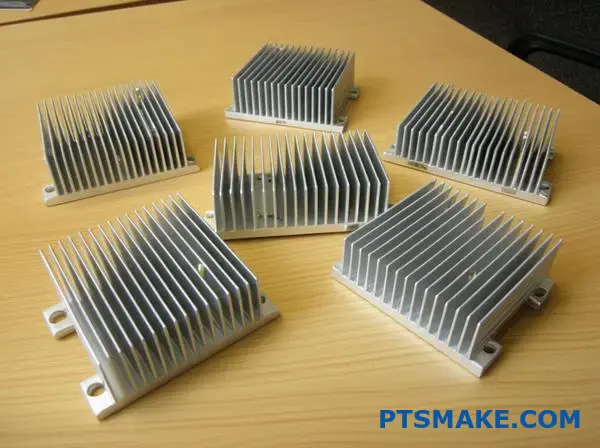
What are typical applications for skived pin heat sinks?
Skived pin heat sinks excel where high heat density meets limited space. You’ll find them in demanding electronics.
Their unique design makes them ideal for cooling components that generate intense, concentrated heat.
High-Performance Computing
High-power CPUs and GPUs are prime examples. Their compact size and high thermal output require efficient cooling. Skived fins provide a massive surface area to dissipate this heat quickly, especially with forced airflow from fans.
Power and Communication Electronics
You also see them in power electronics like IGBTs, servers, and telecommunication equipment. These applications demand reliability and consistent performance. The single-piece construction of a skived heat sink ensures a solid thermal path.
Here’s a quick breakdown:
| Application | Key Challenge | Why Skiving is a Good Fit |
|---|---|---|
| CPUs/GPUs | High heat flux | Dense pins maximize surface area |
| Server Components | 24/7 reliability | One-piece design prevents failure |
| LED Lighting | Long-term performance | Even heat dissipation, no hot spots |
| Telecom Equipment | Compact spaces | High aspect ratio fins are efficient |
Let’s look deeper into why skiving is often the best choice for these specific cases. It’s not just about the fin density; it’s about structural integrity and long-term thermal performance.
The Advantage in Server Components
Servers operate continuously, so component failure is not an option. Bonded or stamped heat sinks have joints between the base and fins. These joints can degrade over time, increasing thermal resistance.
A skived pin heat sink is machined from a single block of copper or aluminum. This monolithic design eliminates any interface material. This provides a consistent and very low thermal impedance11 throughout the product’s entire life. At PTSMAKE, we recommend this for any application where long-term reliability is the primary concern.
Why It Works for LED and Telecom
In high-power LED lighting, maintaining a stable temperature is crucial. It directly impacts the LED’s lifespan and color accuracy. The uniform structure of a skived heat sink pulls heat away evenly. This prevents localized hot spots that can cause premature failure.
For telecommunication equipment, components are packed tightly. Airflow is often complex and restricted. Skived pins can be made very thin and tall, creating an optimal profile for capturing heat in these challenging environments.
Skived pin heat sinks are go-to solutions for high-density electronics. They cool powerful CPUs, servers, and LEDs effectively. Their single-piece construction ensures superior reliability and consistent thermal performance, making them ideal for demanding, long-life applications where failure is not an option.
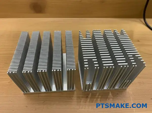
How does pin shape and arrangement impact airflow?
The design of a heat sink is more than just size. Pin geometry and layout are critical. They directly control how air moves through the fins.
This isn’t just theory. The right choices can dramatically improve cooling performance for your specific application.
Pin Geometry Choices
Square pins often provide more surface area. But round-top pins can sometimes offer lower resistance to airflow. The choice depends on the fan’s power.
Arrangement Strategy
Arrangement also matters. We must consider how in-line and staggered patterns affect air turbulence and pressure, which I’ll detail below.
| Pin Shape | Primary Advantage | Best For |
|---|---|---|
| Square | Maximum Surface Area | Low-velocity airflow applications |
| Round-Top | Lower Airflow Resistance | High-velocity airflow applications |
Choosing the right pin design is a balancing act. It involves managing airflow turbulence and pressure drop. Each factor directly influences cooling efficiency.
Turbulence: Friend or Foe?
Turbulence is when air moves chaotically. A staggered pin arrangement creates more turbulence. This disrupts the insulating Boundary Layer12 of air around each pin.
This disruption forces more air molecules to contact the pin surface. The result is better heat transfer. However, this comes at a cost.
Understanding Pressure Drop
Increased turbulence also means higher resistance, or pressure drop. This forces the system’s fan to work harder. If the fan can’t overcome this pressure drop, airflow will decrease.
This could negate the cooling benefits of the turbulence. In contrast, an in-line arrangement offers a clear path. This results in less pressure drop but also less effective heat transfer.
At PTSMAKE, we help clients model this balance. We ensure the heat sink, whether it’s a standard or a skived pin heat sink, matches their fan’s performance curve perfectly.
| Arrangement | Turbulence Level | Pressure Drop | Ideal Scenario |
|---|---|---|---|
| In-Line | Low | Low | Systems with low-power fans or open spaces |
| Staggered | High | High | Systems with powerful fans, tight spaces |
Pin shape and arrangement create a trade-off between thermal performance and airflow resistance. Staggered, square pins offer high surface area and turbulence but create a large pressure drop. The best design always depends on the specific fan and system constraints.
What is the cost structure versus other manufacturing methods?
Understanding the true cost is key. It is not just about the price per piece. You must look at the total project investment.
Different manufacturing methods have very different cost models. For a skived pin heat sink, the financial advantage is clear in certain scenarios.
Let’s break down how skiving compares to a common method like extrusion. This analysis ensures you make the smartest business decision for your budget.
The most significant cost difference is the initial investment. Skiving technology completely eliminates tooling costs, which is a game-changer.
Zero Tooling Investment
Traditional methods like extrusion or die casting require custom dies. These tools can be expensive and take weeks to produce. This upfront cost can be a major hurdle for new projects or prototypes.
At PTSMAKE, we often see this with clients developing innovative products. Skiving allows them to get physical parts quickly without a large capital outlay. This avoidance of Non-Recurring Engineering13 costs is a massive benefit for low-volume production.
Unit Cost Dynamics
While skiving wins on tooling, its per-unit cost can be higher than extrusion at large volumes. The skiving process is meticulous for each individual heatsink.
Extrusion, in contrast, has a high entry cost for the die. But once that tool is made, producing thousands of units becomes incredibly cheap per piece.
This creates a clear break-even point.
| Cost Component | Skiving Process | Extrusion Process |
|---|---|---|
| Tooling (NRE) | None | Significant |
| Per-Unit Cost | Consistent | Decreases with volume |
| Lead Time | Short | Long (due to tooling) |
| Best Use Case | Prototypes, Low Volume | High-Volume Production |
Your required production volume is the most important factor. It directly determines which manufacturing method is the most economical for your project.
Skiving is highly cost-effective for prototypes and low-volume runs due to zero tooling fees. For mass production, methods like extrusion become cheaper in the long run. Your decision should always be based on the project’s total required quantity.
How does a skived pin heat sink’s performance scale?
A skived pin heat sink’s effectiveness is not a fixed value. It changes dramatically based on its environment. Two key factors dictate its performance: airflow and heat load.
The Airflow and Heat Load Dynamic
Increased airflow from a fan directly improves cooling. More air moving across the fins dissipates heat faster. But there is a point of diminishing returns.
Understanding the Curve
The relationship isn’t a straight line. Datasheets show this with a performance curve. This helps you select the right solution.
| Airflow (CFM) | Typical Thermal Resistance (°C/W) |
|---|---|
| 10 | 0.95 |
| 20 | 0.65 |
| 30 | 0.50 |
| 40 | 0.42 |
As you can see, doubling the airflow does not halve the resistance.
Decoding a Performance Curve
When you look at a datasheet for a skived pin heat sink, you’ll see a graph. This chart plots thermal resistance against airflow. It’s the key to understanding performance.
Thermal Resistance vs. Airflow
Thermal resistance, measured in °C/W, tells you how much the temperature rises per watt of heat. Lower is always better. As airflow increases, thermal resistance drops sharply at first.
Then, the curve begins to flatten. This indicates diminishing returns. Pushing more air yields smaller and smaller gains in cooling. This happens as the air changes from a smooth laminar flow14 to a more turbulent one, which can be less efficient at carrying heat away uniformly.
The Role of Heat Load
A heat sink’s performance also depends on the heat it must dissipate. A solution perfect for a 60W processor will struggle with a 120W one under the same airflow conditions.
At PTSMAKE, we often analyze these curves with clients. We help them find the sweet spot. It’s about balancing fan speed, noise, and required thermal performance for their specific device.
| Heat Load (W) | Airflow (CFM) | Expected Temp Rise (°C) |
|---|---|---|
| 50 | 20 | 32.5 |
| 100 | 20 | 65.0 |
| 100 | 40 | 42.0 |
A skived pin heat sink’s performance improves with more airflow, but with diminishing returns. Analyzing the thermal resistance curve on a datasheet is crucial for matching the heat sink to the specific heat load and airflow conditions of your application.
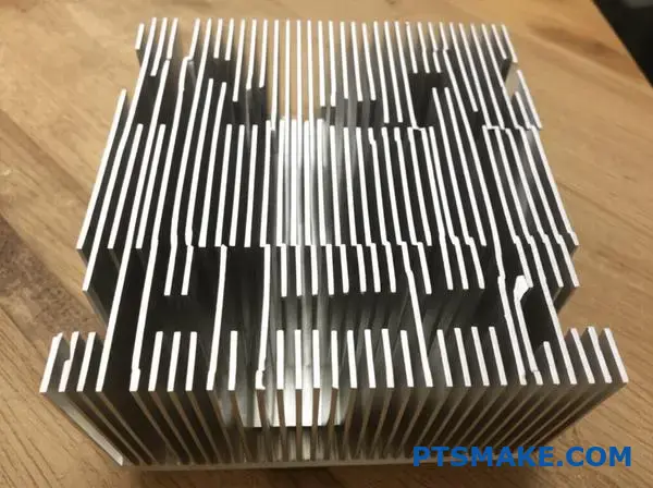
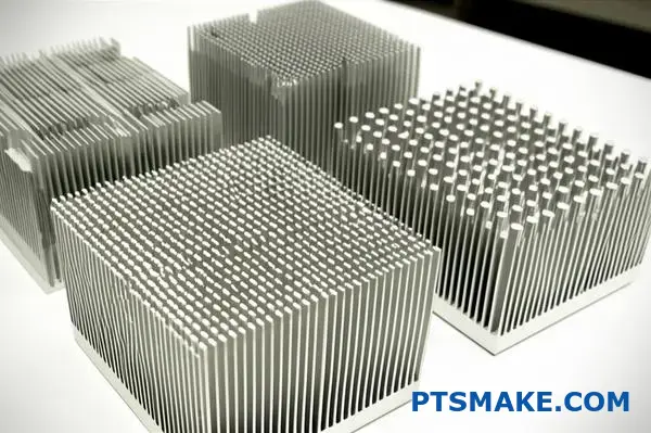
How do you classify designs by pin density?
Classifying skived pin heat sink designs by pin density is crucial. It helps match the right solution to a specific thermal challenge. We generally group them into three main categories.
Low-Density Arrays
These designs feature wider spacing between pins. They are perfect for passive cooling scenarios where natural convection is the primary method of heat dissipation.
Medium-Density Arrays
This is the versatile middle ground. It offers a balance between surface area and airflow resistance. It works well with low-velocity forced air systems.
High-Density Arrays
With very narrow gaps between pins, these maximize surface area. They demand high-velocity airflow from fans to perform effectively.
| Density Category | Typical Pin Pitch | Ideal Airflow |
|---|---|---|
| Low-Density | > 2.5 mm | Passive / Natural Convection |
| Medium-Density | 1.5 – 2.5 mm | Low-Velocity Forced Air |
| High-Density | < 1.5 mm | High-Velocity Forced Air |
Choosing the correct pin density is a balancing act. It directly links thermal performance to your system’s airflow capabilities. It’s a fundamental decision we address early in any project at PTSMAKE.
Low-Density for Passive Cooling
Low-density skived pin heat sink designs are ideal for applications without fans. The wide fin spacing allows air to move freely via natural convection. This makes them suitable for silent operation in consumer electronics or outdoor enclosures. They offer lower backpressure, which is key here.
Medium-Density: The All-Rounder
Medium-density designs are often the default choice. They provide a significant increase in surface area over low-density options without creating excessive air resistance. They are perfect for devices with small, low-power fans where a balance is needed.
High-Density for Demanding Applications
When maximum cooling is required in a compact space, high-density is the answer. These designs are paired with powerful fans to push air through the dense fin array. This setup greatly lowers the overall thermal resistance15 but increases system noise and power consumption.
| Density Level | Key Advantage | Main Trade-Off |
|---|---|---|
| Low | Excellent for passive cooling | Lower surface area |
| Medium | Balanced performance | Not optimal for extremes |
| High | Maximum heat dissipation | Requires high airflow |
Pin density dictates how a skived pin heat sink performs. Low-density is for passive cooling, while high-density requires active, high-velocity air. Medium-density offers a flexible solution for many common applications, balancing surface area with airflow resistance.
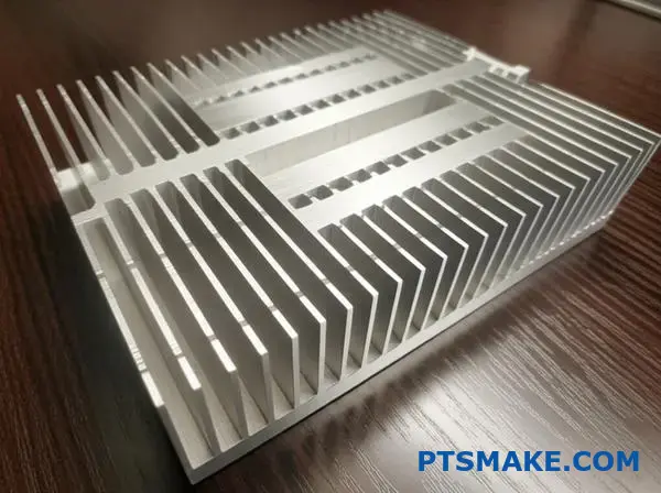
How to choose between a straight fin or pin fin skived design?
Choosing the right fin design depends entirely on your system’s airflow. This single factor is the most critical element. Making the right choice ensures optimal thermal performance.
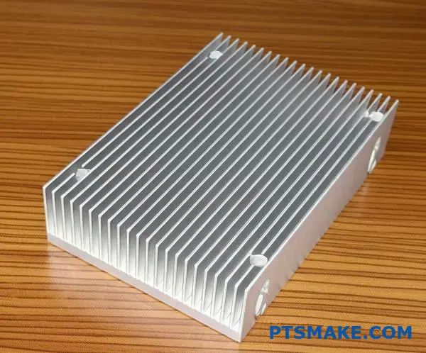
Straight Fins for Linear Airflow
Straight fins are the best choice for linear, unobstructed airflow. Think of systems with ducted fans that push air in one direction. They offer minimal resistance here.
Pin Fins for Complex Airflow
Pin fins shine in complex environments. If airflow is low-speed, multi-directional, or blocked by other components, pin fins are superior. They create turbulence, which enhances cooling.
A simple guide:
| Airflow Type | Recommended Fin Design | Key Advantage |
|---|---|---|
| Linear & Unobstructed | Straight Fin | Low Pressure Drop |
| Low-Speed or Obstructed | Pin Fin | Enhanced Turbulence |
| Multi-directional | Pin Fin | Captures Air Effectively |
A Deeper Look at Airflow Dynamics
Understanding your airflow path is the first step. You need to know how air moves through your enclosure. Are there cables or components in the way?
In our projects at PTSMAKE, we always begin with a thermal analysis. This helps us visualize the airflow and prevent costly design mistakes down the line.
The Efficiency of Straight Fins
Straight fins create a clear channel for air. This design minimizes pressure drop, allowing fans to work most efficiently. They are perfect for high-velocity, directed airflow scenarios.
Based on our tests, this design is highly effective. It is often used in applications where a powerful, consistent airstream is guaranteed.
The Power of Pin Fins
A skived pin heat sink works by disrupting the air’s boundary layer. The pins generate tiny vortices, mixing the air. This process improves Forced convection16 and pulls more heat away.
This is especially useful in cramped spaces. Here, airflow might be weak or unpredictable. The pin design makes the most of whatever airflow is available.
| Application Example | Dominant Airflow | Optimal Fin Choice |
|---|---|---|
| 1U Server Rack | High-speed, Ducted | Straight Fin |
| LED Lighting Fixture | Natural Convection | Pin Fin |
| Portable Electronics | Low-speed, Obstructed | Pin Fin |
Your decision on fin design is dictated by airflow. Straight fins are for direct, linear paths, while pin fins excel in low-speed, obstructed, or multi-directional environments by creating turbulence to improve heat dissipation.
How to balance performance vs. weight for an aerospace application?
In aerospace, every gram counts. This creates a critical trade-off, especially for thermal management. Copper offers superior thermal conductivity. However, its weight can be a significant penalty for flight applications.
This forces us to explore lighter alternatives. Aluminum is often the first choice. It provides a good balance of performance and weight. But material selection is just one piece of the puzzle.
The Material Dilemma
Choosing the right material is a foundational step. The decision directly impacts the final weight and thermal efficiency of the component.
| Material | Thermal Conductivity (W/mK) | Density (g/cm³) |
|---|---|---|
| Copper | ~400 | 8.96 |
| Aluminum (6061) | ~167 | 2.70 |
This table clearly shows the challenge. You get great performance with copper, but at more than three times the weight of aluminum.
Moving beyond basic metals opens up new possibilities. Advanced composites, for instance, offer incredible strength-to-weight ratios. Their properties can be tailored for specific needs, though this often increases manufacturing complexity and cost.
However, the real gains come from design optimization. This is where advanced simulation tools become indispensable for our team at PTSMAKE.
Optimizing Geometry with CFD
Computational Fluid Dynamics (CFD) is a powerful tool. It allows us to simulate airflow and heat transfer without building physical prototypes. We can test dozens of design iterations digitally.
This helps us refine the geometry of components like a Skived pin heat sink. We can optimize fin spacing, height, and thickness to maximize surface area and cooling efficiency while using the least amount of material possible.
Working with clients, we have found that materials like advanced composites can be highly anisotropic17. Their thermal properties change depending on the direction of heat flow, adding another layer to our analysis.
| Analysis Step | Goal | Tool/Method |
|---|---|---|
| 1. Baseline | Establish performance with copper | Material Spec Sheet |
| 2. Alternative | Evaluate aluminum performance | Material Spec Sheet |
| 3. Optimization | Refine geometry for weight reduction | CFD Simulation |
| 4. Validation | Test optimized prototype | Physical Benchmarking |
This structured approach ensures we methodically shave off every possible gram without compromising on the required performance.
Balancing weight and performance in aerospace is a complex task. It requires smart material selection, from aluminum to advanced composites, and leveraging powerful simulation tools like CFD to optimize every aspect of the design for maximum efficiency.
What are emerging trends in skived fin technology?
Skived fin technology is constantly evolving. We are seeing major advancements that push thermal performance limits. The future is focused on precision and material innovation.
These trends allow for more effective heat dissipation. This is critical in increasingly compact and powerful electronics.
Finer Fin Pitches
The drive for smaller and more dense fins is key. Finer pitches increase the surface area available for heat transfer. This improves efficiency without enlarging the heatsink’s footprint.
Advanced Material Integration
We are moving beyond just copper and aluminum. New materials and alloys are being tested. These materials offer better thermal properties or lighter weight.
| Feature | Traditional Skiving | Emerging Trends |
|---|---|---|
| Fin Pitch | > 0.5 mm | < 0.3 mm |
| Materials | Copper, Aluminum | Advanced Alloys, Composites |
| Base Structure | Solid Block | Complex, Integrated |
The future of skived fins is not just about refining existing methods. It involves combining technologies to create truly innovative solutions. This is where things get really exciting for us as engineers.
Hybrid Manufacturing Processes
One of the most promising trends is hybrid manufacturing. We are exploring skiving fins onto a base created using additive manufacturing18. This approach opens up entirely new design possibilities.
This method allows for complex internal channels. Imagine a skived pin heat sink with integrated liquid cooling paths. These are geometries that traditional machining simply cannot produce. It blends the high surface area of skiving with the design freedom of 3D printing.
Improved Surface Texturing
Another area of innovation is surface texturing. We are testing micro-textures on fin surfaces. These textures are designed to disrupt the air’s boundary layer. This enhances convective heat transfer.
Based on our research, this technique can boost efficiency. It improves performance without changing the heatsink’s overall size.
| Surface Finish | Heat Transfer Efficiency Improvement |
|---|---|
| Smooth Surface | Baseline |
| Micro-Textured | Up to 15% |
These emerging trends—finer pitches, advanced materials, hybrid processes, and surface texturing—are pushing the boundaries of thermal management. They enable more powerful and compact electronic designs, opening doors for next-generation technology.
Start Your Skived Pin Heat Sink Project with PTSMAKE Today
Ready to optimize your next-generation hardware with cutting-edge Skived Pin Heat Sinks? Contact PTSMAKE now for a fast, competitive quote and expert engineering support. Transform your prototypes and production runs with unmatched precision, reliability, and attention to detail. Send your inquiry today!

Dive deeper into the science of this key barrier to effective thermal management. ↩
Understand how this key metric is calculated and used to evaluate heat sink efficiency. ↩
Understand how fluid dynamics between fins impacts your heatsink’s real-world performance. ↩
Learn more about how this phenomenon impacts machining precision. ↩
Discover how this manufacturing technique creates high-density fins for superior thermal performance in compact spaces. ↩
Understand how this critical metric impacts component temperature and overall system reliability. ↩
Learn how this key property measures a material’s resistance to heat flow. ↩
Learn how this ratio of fin height to fin thickness impacts thermal efficiency. ↩
Understand how this key metric directly affects your device’s temperature and reliability. ↩
Understand how this thin layer of air affects cooling efficiency. ↩
Discover how this key metric impacts cooling efficiency and the overall reliability of your components. ↩
Discover how this thin layer of air affects thermal performance and design efficiency. ↩
Learn how these one-time engineering costs impact your total project budget and manufacturing choices. ↩
Learn how different airflow characteristics can directly influence your thermal management strategy. ↩
Learn how this key metric determines your heat sink’s cooling efficiency. ↩
Learn more about how different airflow types impact heat transfer efficiency in thermal management systems. ↩
Understand how anisotropic properties impact material performance in complex designs. ↩
Click to understand how this 3D printing technology is revolutionizing heat sink design and manufacturing. ↩