You’re selecting timing pulleys for your precision application, but the overwhelming variety of profiles, materials, and specifications makes choosing the right solution feel like navigating a technical maze. One wrong choice—whether it’s profile mismatch, incorrect material selection, or poor construction type—can lead to premature wear, system failure, and costly downtime that disrupts your entire production schedule.
Custom timing pulleys require careful selection of profile type, material, and construction based on your specific application requirements, operating environment, and performance demands to ensure optimal power transmission and system reliability.
I’ve worked with many engineers who initially focused only on basic specifications like pitch and tooth count, only to discover that factors like material selection, construction type, and profile compatibility are equally critical for long-term success. This guide covers the essential considerations that will help you make informed decisions for your timing pulley applications.
Why are different materials used for manufacturing timing pulleys?
Ever wonder why a timing pulley isn’t a one-size-fits-all component? The material choice is critical. It directly shapes the performance, efficiency, and lifespan of your machinery.
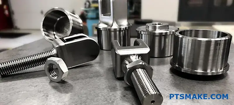
At PTSMAKE, we frequently use aluminum, steel, and plastics. Each material brings distinct advantages to the table. Choosing the right one ensures your system runs optimally.
A Quick Material Overview
The best material depends entirely on the job. A pulley for a high-speed robot has different needs than one for a heavy-duty conveyor.
Here is a simple breakdown:
| Material | Key Benefit | Common Use Case |
|---|---|---|
| Aluminum | Lightweight | High-speed motion |
| Steel | High Strength | Heavy-duty loads |
| Plastics | Corrosion Resistance | Wet environments |
This decision is the first step toward a reliable motion control system.
Choosing a timing pulley material goes beyond just cost. It’s about matching the material’s properties to the application’s specific demands. A mismatch can lead to premature failure and costly downtime. Let’s look closer at the main options.
Aluminum: The Need for Speed and Coolness
Aluminum is the go-to for applications requiring rapid acceleration and deceleration. Its low inertia means less energy is needed to start and stop it. This makes it perfect for robotics and 3D printers. It also dissipates heat well, protecting the belt in high-speed operations.
Steel: The Powerhouse for Heavy Lifting
When torque and durability are non-negotiable, steel is the answer. It can handle extreme loads without deforming or wearing out. Its high tensile strength1 makes it ideal for industrial machinery, automotive engines, and heavy-duty conveyor systems where failure is not an option.
Plastics: The Quiet and Clean Operator
Plastic timing pulleys, often made from Nylon or Acetal, offer unique benefits. They are naturally quiet, making them suitable for office equipment. They are also corrosion-resistant, which is essential in food processing or medical applications. Plus, they are often the most cost-effective choice for lighter loads.
| Property | Aluminum | Steel | Plastics (e.g., Nylon) |
|---|---|---|---|
| Inertia | Low | High | Very Low |
| Torque Capacity | Moderate | High | Low to Moderate |
| Noise Level | Moderate | High | Low |
| Corrosion Resistance | Good (with anodizing) | Poor (unless stainless) | Excellent |
| Cost | Moderate | High | Low |
The choice is clear once you define your priorities. Whether it’s speed, strength, or stealth, there is a material perfectly suited for your timing pulley needs.
The material selection for a timing pulley is a strategic engineering decision. Aluminum suits high-speed, low-inertia systems. Steel is essential for high-torque and durable applications, while plastics offer a quiet, corrosion-resistant, and cost-effective solution for specific environments.
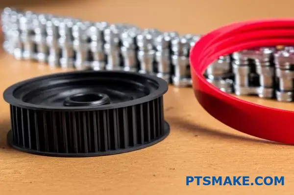
What is the primary functional purpose of pulley flanges?
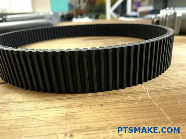
Pulley flanges have a simple yet vital job. They act as physical guides for the timing belt.
Their main function is to keep the belt centered on the pulley. This prevents the belt from "walking" or slipping off the edge during operation.
Think of them as guardrails. They ensure the belt stays in its intended path, which is crucial for the reliability and precision of any timing pulley system.
The Rule of Thumb for Flanging
A common question is how many flanges are needed. The answer depends on the system’s complexity. Over-flanging can cause problems.
Here is a general guide we use at PTSMAKE.
| System Type | Flange Recommendation |
|---|---|
| Two-Pulley System | Flange only one of the two pulleys |
| Multi-Pulley System | Flange every other pulley |
This approach provides enough guidance without over-constraining the belt.
Why Not Flange Every Pulley?
While flanges are essential, using too many is a mistake. It might seem like more flanges offer better security, but the opposite is often true.
When you flange every pulley, you over-constrain the system. The belt has no room for minor, natural movement. This creates friction against the flange edges.
This constant rubbing can cause the edges of the timing belt to fray and wear out prematurely. It also increases operational noise and reduces the system’s overall efficiency.
The real cause of belt walking is often not a lack of flanges.
Common Causes of Belt Walking
In our experience, issues like shaft misalignment or improper tension are the true culprits. A perfectly aligned system with correct tension often needs minimal flanging. The belt will track naturally.
This unwanted movement, known as lateral drift2, is often caused by minor misalignments that are hard to detect visually.
Here are the key factors to check before adding more flanges.
| Factor | Impact on Belt Tracking |
|---|---|
| Shaft Misalignment | The primary cause of belt walking. |
| Improper Belt Tension | Too loose or too tight affects tracking. |
| Pulley Parallelism | Pulleys must be perfectly parallel. |
| Excessive Vibration | Can cause the belt to wander. |
Focusing on these mechanical fundamentals is more effective than relying on flanges to fix an underlying problem.
Pulley flanges are essential guides that prevent the timing belt from walking off. The general rule is to flange one pulley in a two-pulley system or every other pulley in a multi-point drive. This provides control without causing excessive wear from over-constraining the belt.
When is a timing pulley superior to V-belts or chains?
Choosing the right drive system is critical. It impacts your machine’s performance and reliability. You must consider your specific application needs.
Is precision your top priority? Or do you need raw power and durability? Let’s break down the key factors.
Key Application Needs
This simple framework helps guide the decision. It focuses on the primary function your system needs to perform.
| Feature | Best For | Why? |
|---|---|---|
| Precision | Timing Pulley | No slippage, exact positioning |
| High Torque | Chain Drive | Strong, handles heavy loads |
| Low Cost | V-Belt | Simple design, widely available |
| Low Noise | Timing Pulley | Smooth engagement, no metal contact |
Let’s dive deeper into this framework. Your choice directly affects your final product’s quality and operational costs. In past projects at PTSMAKE, we’ve seen how the right selection prevents costly redesigns later.
For High-Precision Applications
If your application demands perfect synchronization, a timing pulley is the clear winner. Think of robotics or automated assembly lines. Any slip can ruin the entire operation.
Chains and V-belts cannot guarantee this level of accuracy. They have inherent slip or stretch. A timing pulley system’s non-slip engagement ensures consistent, repeatable motion every time.
When Power and Durability Matter Most
For heavy-duty tasks, chains are often the go-to. They are robust and handle shock loads well. But they are noisy and require regular lubrication.
V-belts offer a middle ground. They absorb shock and vibration well, protecting motors and bearings. The goal is to avoid unwanted backlash3 in the system.
Comparing Maintenance and Operational Costs
Based on our tests, the long-term operational costs differ significantly. This is a key factor for our clients.
| System | Maintenance Needs | Noise Level |
|---|---|---|
| Timing Pulley | Very Low | Quiet |
| V-Belt | Moderate (Tensioning) | Low |
| Chain Drive | High (Lubrication) | Loud |
Your application dictates the best choice. A timing pulley excels in precision and low maintenance. Chains are for high torque, while V-belts are a cost-effective solution that absorbs shock. Each has an ideal use case.
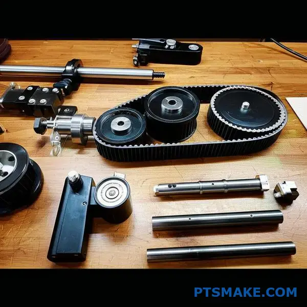
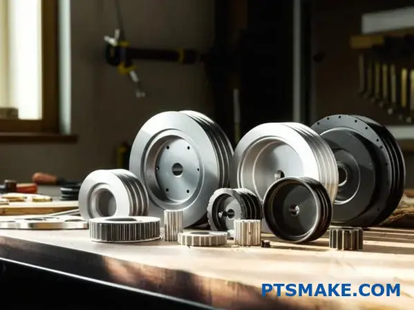
Beyond the Pulley: Key Components of the Assembly
A timing pulley is just one piece of a puzzle. A complete system is an assembly where every part matters. Thinking about the entire system is crucial.
It prevents unexpected failures down the line. A successful design depends on how well these parts interact.
The Essential Parts
A robust system always includes several key elements. Each one has a specific job to do.
| Component | Primary Function |
|---|---|
| Driver Pulley | Transmits power from the motor. |
| Driven Pulley | Receives power and drives the load. |
| Timing Belt | Synchronizes the pulleys’ rotation. |
| Shafts & Bearings | Support the pulleys and allow rotation. |
| Tensioner | Maintains proper belt tension. |
Understanding this complete picture is the first step. It ensures long-term operational reliability.
The Symphony of Interaction
Viewing the system holistically is non-negotiable. At PTSMAKE, we always analyze the entire assembly for our clients. A high-precision timing pulley is useless if the shaft deflects under load.
Or if the bearings are not suitable for the required speed. Every component influences the others.
How Parts Affect Each Other
Consider the tensioner. Too much tension wears out the belt and bearings prematurely. Too little tension allows the belt to slip, destroying synchronization. This delicate balance is key.
Similarly, the selection of bearings is critical. Based on our tests, proper bearing preload4 is crucial for minimizing shaft play. This ensures the timing pulley runs true and maintains accuracy.
The interaction between these parts defines the system’s performance and lifespan. A failure in one part often signals an issue with the system’s design, not just the component itself.
| Component | Common Interaction Issue | Result |
|---|---|---|
| Shaft | Material too soft | Deflection under load, pulley misalignment. |
| Bearings | Incorrect tolerance | Increased friction, premature wear. |
| Belt | Wrong tension | Slipping or accelerated component failure. |
| Pulley | Poor concentricity | Vibration and loss of precision. |
A successful system is a well-balanced one.
A complete timing pulley system is an interconnected assembly. Each part, from the timing pulley to the bearings, must work in harmony. A holistic view is essential for achieving reliability and peak performance in any application.
What are the major international standards for timing pulleys?
When selecting a timing pulley, standards are not just guidelines. They are the foundation of reliability. They ensure parts from different makers work together.
Key bodies create these rules. This guarantees compatibility across the global supply chain. It simplifies everything from design to repair.
Major Standards Bodies
| Abbreviation | Full Name | Focus Area |
|---|---|---|
| ISO | International Organization for Standardization | Global standards for various industries |
| DIN | Deutsches Institut für Normung | German national standards, widely adopted |
| RMA | Rubber Manufacturers Association | U.S. standards, especially for belts |
These standards ensure every timing pulley meets precise specifications.
Why Interchangeability is Critical
Imagine your production line stops. A single timing pulley has failed. Without standards, you must find the original manufacturer. This could take days or weeks.
Standardization solves this problem. A pulley that meets ISO standards can be replaced with any other ISO-compliant pulley. This concept of interchangeability5 is vital.
It provides sourcing flexibility. You are not locked into one supplier. This freedom helps manage costs and reduce supply chain risks.
Impact on Maintenance and Sourcing
| Aspect | Standardized Parts | Non-Standardized Parts |
|---|---|---|
| Sourcing | Multiple suppliers, competitive pricing | Single supplier, potential monopoly |
| Lead Time | Often in stock, short delivery | Custom order, long delivery |
| Maintenance | Quick replacement, minimal downtime | Lengthy repairs, significant downtime |
| Risk | Low risk of incompatibility | High risk of system failure |
At PTSMAKE, we machine every timing pulley to strict international standards. This guarantees our parts fit seamlessly into your existing systems. It simplifies your maintenance and procurement processes, ensuring reliability from day one. This commitment is key for our clients’ success.
Standards from bodies like ISO, DIN, and RMA are essential. They create a universal language for timing pulley specifications. This ensures parts from any certified manufacturer will be interchangeable, which is fundamental for flexible sourcing, simplified maintenance, and overall operational reliability.
How are trapezoidal profiles (e.g., XL, L, H) categorized?
Classic trapezoidal profiles are simple. They are categorized primarily by their pitch. This single dimension dictates their size and power handling capability.
A larger pitch means a larger tooth. This allows for more engagement with the timing pulley and higher torque transfer. It’s a straightforward system.
Pitch and Power
The three common imperial profiles are Extra Light (XL), Light (L), and Heavy (H). Their classification is easy to remember.
Here is a quick breakdown:
| Profile | Pitch (inches) | Pitch (mm) | Power Handling |
|---|---|---|---|
| XL | 0.200" | 5.08 mm | Light |
| L | 0.375" | 9.525 mm | Medium |
| H | 0.500" | 12.70 mm | Heavy |
This simple grouping helps engineers quickly select a profile based on initial load estimates for a project.

Application-Specific Choices
Understanding the application is key. The pitch and tooth size directly influence where each profile excels. It’s not just about power, but also about the required motion quality.
XL for Precision and Low Load
The XL profile, with its fine 0.200" pitch, is ideal for instrumentation. Think of 3D printers, plotters, and office equipment. These applications require precise movement but don’t involve high torque.
L and H for General Power Transmission
The L and H profiles are the workhorses. We see them in conveyors, pumps, and general industrial machinery. Their larger teeth can handle significant torque for power transmission tasks. The choice between L and H depends entirely on the load calculations.
The Inherent Limitation: Backlash
However, the trapezoidal shape has a built-in drawback: backlash. The clearance between the belt tooth and the timing pulley groove allows for slight movement when reversing direction. This makes them unsuitable for true high-precision positioning systems where accuracy is critical. This slight sloppiness is a result of the Pitch Line Differential6 between the belt and pulley.
Here’s a summary of their roles:
| Profile | Common Uses | Main Constraint |
|---|---|---|
| XL | Instrumentation, office machines | Low torque |
| L | General machinery, conveyors | Backlash |
| H | High-load power transmission | Backlash |
At PTSMAKE, we often help clients evaluate if a classic trapezoidal profile meets their needs or if they should consider a more advanced curvilinear profile to minimize backlash.
Trapezoidal profiles (XL, L, H) are categorized by pitch, which determines their size and power capacity. XL suits light-duty instruments, while L and H handle general power transmission. Their primary limitation is backlash, making them less ideal for high-precision positioning.
What are advantages of curvilinear profiles (e.g., HTD, GT2)?
Curvilinear profiles, like HTD and GT2, offer significant advantages over older trapezoidal designs. The key is their round tooth shape.
This geometry allows for a much better distribution of stress across the tooth. It avoids the sharp stress concentrations found in trapezoidal profiles.
Better Stress Distribution
The rounded design spreads the load more evenly. This reduces wear and tear on both the belt and the timing pulley. It leads to a longer service life for the entire system.
Higher Torque Capacity
Because stress is managed better, these belts can handle more power. They can transmit higher torque without slipping or failing. This makes them ideal for demanding applications.
| Profile Type | Stress Distribution | Torque Capacity |
|---|---|---|
| Curvilinear (HTD, GT2) | Even | High |
| Trapezoidal | Concentrated at corners | Lower |
The round tooth profile is a simple change with a big impact. It addresses the core weaknesses of the trapezoidal design, enhancing performance across the board. In our work at PTSMAKE, we often recommend these profiles for new high-performance designs.
Reduced Backlash
One of the most critical benefits is reduced backlash. The deep, rounded grooves ensure a snug fit between the belt and the timing pulley teeth. This tight engagement minimizes play or "slop" when the drive system reverses direction. This design effectively minimizes Hertzian stress7 at the tooth root, contributing to longevity.
Smoother Engagement
The teeth roll into and out of the pulley grooves smoothly. This is different from the harsher, sliding action of trapezoidal teeth. The result is quieter operation and less vibration, which is crucial for precision machinery.
GT2 for Precision Applications
The GT2 profile is a further evolution of this concept. It’s specifically designed for extremely low backlash. This makes it the standard choice for applications where positional accuracy is everything. Think of 3D printers, CNC machines, and robotics.
| Profile | Primary Advantage | Common Application |
|---|---|---|
| HTD | High torque transmission | Industrial Conveyors, Automotive |
| GT2 | Minimal backlash, precision | 3D Printers, Robotics, CNC |
The choice between HTD and GT2 often depends on whether the priority is raw power transmission or pinpoint accuracy.
The round tooth shape of curvilinear profiles provides superior performance. It leads to better stress distribution, higher torque capacity, and reduced backlash. This makes them ideal for modern, high-precision applications compared to older trapezoidal designs.
When would you choose a modified curvilinear profile (e.g., PolyChain)?
When standard belts fall short, you need a high-performance profile. Modified curvilinear belts, such as the PolyChain, are genuine powerhouses.
They are engineered as direct replacements for roller chains. This is for applications needing extremely high torque and power transmission. They are a modern, cleaner, and often better solution.
Primary Use Case
These profiles excel where traditional drives struggle. They handle the toughest industrial tasks with ease, from conveyors to crushers.
| Feature | Ideal Application |
|---|---|
| Power | High-horsepower drives |
| Torque | Very high, low-speed |
| Replacement | Roller chain systems |
The Roller Chain Alternative
The main reason to choose these profiles is to replace roller chains. Chains are effective but come with drawbacks. They are heavy, noisy, and need constant lubrication. This creates mess and high maintenance needs.
In past projects, we’ve seen clients switch for a few key benefits.
Reduced Maintenance and Enhanced Cleanliness
These belts run completely dry. No oil or grease is needed. This is a critical advantage in food processing or textile manufacturing. Any risk of product contamination is eliminated. It also simplifies the entire maintenance process.
Lower Weight and Noise
A PolyChain-style belt is significantly lighter than a comparable roller chain. This reduces the overall weight and inertia of a system. The internal tensile cords8 provide the strength without the mass of steel. This often leads to better energy efficiency. They are also much quieter, which improves the workplace environment. For these systems to work, a perfectly machined timing pulley is non-negotiable.
| Parameter | Roller Chain | Modified Curvilinear Belt |
|---|---|---|
| Lubrication | Required | Not Required |
| Noise Level | High | Low |
| Weight | Heavy | Light |
| Stretch | Yes (over time) | Negligible |
Modified curvilinear profiles are elite solutions for high-torque applications. They directly replace roller chains, offering a lighter, quieter, and maintenance-free alternative without sacrificing power. This makes them ideal for demanding industrial environments where cleanliness and reliability are key.
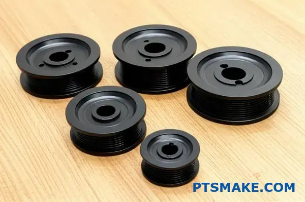
What are the common construction types of timing pulleys?
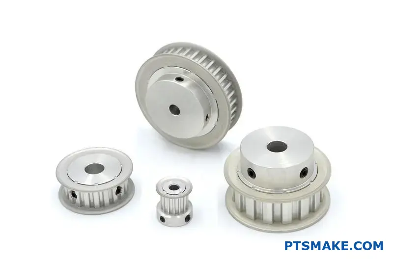
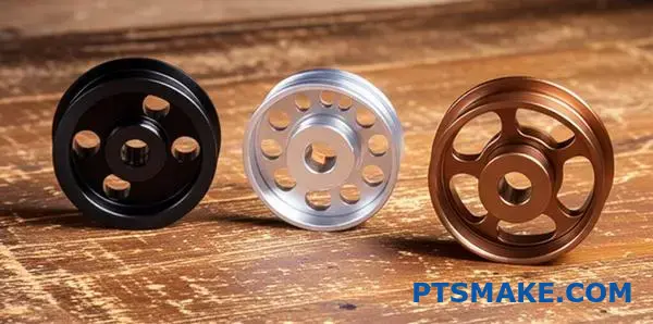
The physical shape of a timing pulley is not just about aesthetics. It is a critical design choice. This choice directly impacts the pulley’s weight, strength, and overall performance.
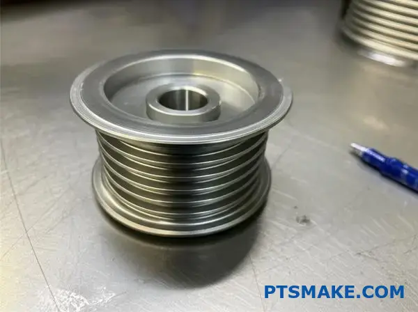
Solid Pulleys
For smaller diameter pulleys, a solid construction is often standard. This design offers maximum rigidity and is simple to manufacture.
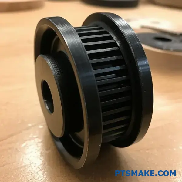
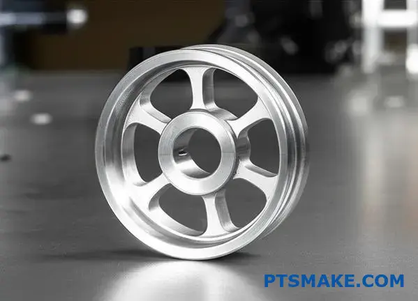
Webbed and Spoked Pulleys
As pulley sizes increase, reducing weight becomes important. Webbed and spoked designs achieve this by removing material from the pulley’s center. This is key for efficiency.
| Construction | Typical Diameter | Primary Benefit |
|---|---|---|
| Solid | Small | Maximum Rigidity |
| Webbed | Medium | Weight Reduction |
| Spoked | Large | Low Inertia |
The Engineering Behind Pulley Shapes
The choice between solid, webbed, or spoked is a calculated engineering decision. It optimizes a timing pulley for its specific function within a machine.
From Solid to Spoked
Solid pulleys are robust and usually machined from a single piece of bar stock. Their mass is acceptable for small systems where performance is not limited by weight.
A webbed design introduces a thin plate connecting the hub to the rim. This offers a great compromise, reducing weight while retaining significant structural strength for medium-sized applications.
Spoked pulleys remove the most material. This design drastically lowers the rotational inertia9 of the pulley.
Performance in Dynamic Systems
This matters most in high-speed systems. Applications requiring rapid acceleration, deceleration, or direction changes benefit immensely from low-inertia spoked pulleys.
In past projects at PTSMAKE, we’ve helped clients select spoked designs for robotics and automation. This allowed their systems to move faster and more efficiently.
| Pulley Type | Best For… | Key Performance Factor |
|---|---|---|
| Solid | Low-speed, small systems | Durability, Simplicity |
| Webbed | Medium-speed, moderate loads | Balanced weight/strength |
| Spoked | High-speed, dynamic systems | Fast response, efficiency |
Choosing the right timing pulley construction—solid, webbed, or spoked—is a critical design choice. It directly impacts the pulley’s weight and inertia, which is essential for optimizing performance in high-speed, dynamic systems where precision is key.
How are pulley materials classified by application environment?
Choosing the right material is not just about strength. It is about matching the pulley to its specific workplace. A material that excels indoors might fail quickly in a corrosive or high-heat setting.
This classification ensures long-term reliability.
Standard Operating Environments
For most applications, standard materials work perfectly. They offer a great balance of performance and cost.
Aluminum
Lightweight and cost-effective. Ideal for high-speed applications where inertia is a concern.
Steel
Offers superior strength and wear resistance. It’s the go-to for high-load systems. A steel timing pulley provides excellent durability.
| Material | Key Advantage | Best Use Case |
|---|---|---|
| Aluminum | Lightweight | High-speed, low-load automation |
| Steel | High Strength | Heavy machinery, high-torque |
At PTSMAKE, our first step is always to understand the operational environment. This simple analysis prevents costly failures and downtime for our clients. It’s a foundational part of our precision manufacturing process.
Corrosion-Resistant Environments
When moisture, chemicals, or salt are present, you need enhanced protection. Standard materials would degrade too quickly.
Stainless Steel
This is a top choice for resisting rust and chemical damage. It is strong and durable, making it suitable for demanding conditions.
Coated Aluminum
Anodizing or other coatings can give aluminum excellent corrosion resistance. This is great when you still need a lightweight part.
Food-Grade and Medical Environments
These industries have strict hygiene rules. Materials must be non-toxic and easy to clean. Here, the material’s impact on product safety is paramount.
| Material | Primary Benefit | Common Application |
|---|---|---|
| Stainless Steel (304/316) | Highly resistant to corrosion and bacteria | Food processing, pharmaceutical equipment |
| Food-Grade Plastics (PEEK, Acetal) | Lightweight, self-lubricating, chemical resistant | Conveyor systems, packaging machines |
High-Temperature Environments
Extreme heat can cause materials to soften, warp, or lose strength. This requires specialized alloys or high-performance plastics. Material selection here is critical for operational safety and requires careful consideration of its creep resistance10. A proper timing pulley must maintain its integrity under heat.
Choosing the right pulley material is crucial for performance. Standard materials like aluminum and steel suit general use. For harsh conditions, specialized options like stainless steel, coated aluminum, or high-performance plastics are necessary to ensure reliability and longevity in specific applications.
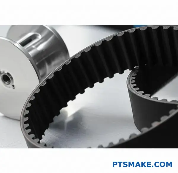
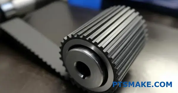
How do you ensure compatibility between belt and pulley profiles?
There is one strict rule you must always follow. The tooth profile of the belt must perfectly match the pulley’s profile. There are no exceptions.
Thinking you can mix and match is a common mistake. It leads to serious performance issues and equipment failure.
The Consequences of Mismatching
Using an incompatible belt and pulley is never a good idea. This mismatch creates inefficiency and risks damaging your entire system.
| Belt Profile | Pulley Profile | Compatibility |
|---|---|---|
| HTD | HTD | Match |
| GT | GT | Match |
| HTD | GT | Mismatch |
| GT | HTD | Mismatch |
This simple chart shows the only way to ensure proper function. Always verify your components match before installation.
The most critical principle is profile matching. You cannot compromise on this. Let’s look at why, using a common example from past projects.
The HTD vs. GT Dilemma
A frequent point of confusion is between HTD (High Torque Drive) and GT (or GT2/GT3) profiles. They look similar, but their tooth geometry is fundamentally different.
Using an HTD belt on a GT pulley results in poor tooth meshing11. The belt teeth won’t seat properly in the pulley grooves. This leads to increased vibration, noise, and slippage under load.
Stress and Wear
This improper fit concentrates stress on the belt’s teeth. It causes premature wear and can lead to tooth shearing. The system loses its precision and reliability. In our tests, we’ve seen mismatched systems fail in a fraction of their expected lifespan.
A correctly selected timing pulley is essential.
| Feature | HTD Profile | GT Profile |
|---|---|---|
| Tooth Shape | Round | Modified Curvilinear |
| Backlash | Higher | Lower |
| Load Capacity | Good | Excellent |
| Best For | General Use | High-Precision |
At PTSMAKE, we always confirm these details with clients. Ensuring the belt and pulley profiles are identical is the first step in building a reliable drive system.
The core rule is simple: belt and pulley profiles must match exactly. Using different profiles together, such as HTD and GT, causes poor performance, excessive wear, and eventual system failure. This compatibility check is non-negotiable for system reliability.
How would you diagnose and solve excessive drive noise?
A systematic approach is crucial. When a drive system gets loud, guessing is inefficient. I always use a troubleshooting flowchart.
This method saves time and prevents misdiagnosis. It breaks the problem into logical steps.
Start with the Obvious
First, check the basics. Is the noise new? Did it start after a change? Simple questions often point to the solution. A well-designed system, especially with a precision timing pulley, should run quietly.
Troubleshooting Flowchart: First Steps
| Symptom | Initial Check | Action |
|---|---|---|
| High-Pitched Whine | Belt Tension | Use a tension gauge |
| Grinding/Rumbling | Pulley Condition | Inspect for wear/damage |
| Clicking/Ticking | Alignment | Check pulley parallelism |
This structured process ensures you don’t miss a potential cause. It is simple but effective.
Diagnosing the Root Cause
Once you’ve done initial checks, dig deeper. Each potential issue requires a specific diagnostic path. A simple noise can point to complex underlying problems if not addressed correctly. This detailed approach is something we prioritize at PTSMAKE. We ensure components are not just made, but made to work together silently.
A Deeper Diagnostic Table
This table links specific noises to their most likely causes and the required fix. Following this logic prevents you from replacing parts that are not the issue.
| Noise Type | Likely Cause | Corrective Action |
|---|---|---|
| Squeal during start/stop | Belt Tension Too Low | Adjust tension to manufacturer specs |
| Constant Whine | Belt Tension Too High | Reduce tension to manufacturer specs |
| Rumbling/Growling | Worn Pulley Bearings | Replace the pulley or bearings |
| Uneven Wear Noise | Pulley Misalignment | Realign pulleys using a laser tool |
Sometimes, the noise isn’t from a single faulty part. It can be the system’s harmonic resonance12 amplifying small vibrations. This often happens with an improper belt and pulley profile match, a mistake that can be costly. We have learned from past projects that component compatibility is as important as individual part quality.
A logical flowchart transforms complex troubleshooting into a series of simple checks. By isolating potential causes for noise—from tension and alignment to component wear—you can pinpoint and resolve the issue efficiently, ensuring the system runs smoothly and quietly.
In a high-speed reversing application, how would you optimize pulley selection?
In high-speed reversing systems, every gram matters. The goal is to minimize inertia. Quick direction changes demand rapid acceleration and deceleration. A heavy pulley fights against these changes. This puts more stress on the motor and belt.
So, how do we reduce this resistance?
Choose Lightweight Materials
First, look at the material. Aluminum is often the best choice over steel. It provides enough strength while being much lighter. This simple switch can significantly cut down pulley weight.
Optimize Pulley Construction
Next, consider the pulley’s design. A solid pulley has unnecessary mass. Webbed or spoked designs remove material from the center. This reduces weight without sacrificing strength where it’s needed most.
Material Comparison
| Feature | Aluminum | Steel |
|---|---|---|
| Density | Low | High |
| Inertia | Lower | Higher |
| Cost | Moderate | Lower |
| Strength | Good | Excellent |
Select a Smaller Pitch
Finally, think about the pitch profile. A smaller pitch allows for a more compact timing pulley. A smaller overall diameter directly leads to lower inertia, which is perfect for these applications.
Minimizing inertia is not just about picking the lightest option. It’s a careful balancing act. A pulley that is too light might lack the structural integrity needed for the application’s torque and speed demands. This could lead to premature failure.
The Role of Inertia in Performance
Inertia is the resistance of an object to any change in its state of motion. For a timing pulley, a lower moment of inertia13 means the motor needs less torque to start, stop, and reverse its rotation. This results in faster response times, reduced energy consumption, and less wear on the entire system.
In our work at PTSMAKE, we guide clients through these trade-offs. We help them find the sweet spot between low inertia and high durability.
Construction Type Analysis
| Construction | Inertia Level | Strength | Best Use Case |
|---|---|---|---|
| Solid | High | Very High | Low-speed, high-torque |
| Webbed | Medium | High | General purpose, high-speed |
| Spoked | Low | Good | High-speed, reversing |
Pitch Profile and System Dynamics
A smaller pitch not only reduces pulley diameter but can also allow for a narrower belt. This further reduces the total mass of the moving system. However, we must ensure the selected profile can handle the required load without tooth jump or excessive wear. It’s a complete system optimization.
Reducing inertia is key for high-speed reversing. You can achieve this by selecting lightweight materials like aluminum, using webbed or spoked constructions, and opting for a smaller pitch profile. This boosts system responsiveness and efficiency.
Unlock Precision Timing Pulley Solutions with PTSMAKE
Ready for superior timing pulley performance? Contact PTSMAKE today for a fast, expert quote on custom timing pulleys and assemblies. Benefit from our precision CNC machining, strict quality control, and rapid turnaround—trusted by industry leaders worldwide. Submit your RFQ and empower your engineering projects with confidence!

Discover how this key property determines a material’s ability to withstand pulling forces without breaking. ↩
Understand the physics of belt movement to improve your machine’s design and reliability. ↩
Learn how backlash impacts precision and how to minimize it in your designs. ↩
Learn how this axial force impacts bearing life and system precision. ↩
Discover how true part interchangeability can drastically lower maintenance costs and reduce equipment downtime. ↩
Understand how this slight mismatch affects belt accuracy and performance. ↩
Learn how contact stress influences material selection and the operational life of components. ↩
Learn how these internal components give high-performance belts their incredible strength and torque capacity. ↩
Learn how inertia impacts the efficiency and responsiveness of your mechanical systems. ↩
Discover how this property impacts material performance and lifespan in high-heat industrial settings. ↩
Discover the engineering behind proper tooth engagement and its direct effect on system precision and power. ↩
Learn how system vibrations are amplified and how to prevent this in your designs. ↩
Learn how this physical property directly impacts your system’s performance and efficiency. ↩