Designing passive heat sinks for high-power electronics feels straightforward until your prototype starts overheating during testing. You realize that aluminum material selection, fin geometry, and thermal interface aren’t just technical specs – they’re the difference between a product that works and one that fails thermal validation.
Passive heat sink design requires balancing thermal conductivity, surface area, and airflow patterns to achieve optimal heat dissipation without external power. Success depends on material selection, manufacturing process, and system-level integration with the enclosure.
Through multiple projects at PTSMAKE, I’ve helped engineers solve thermal challenges across different industries. The key insights I’ll share cover material trade-offs, manufacturing constraints, and troubleshooting methods that can save weeks of redesign time.
What is the first principle of passive heat dissipation?
The first principle is surprisingly simple. It’s rooted in the fundamental laws of physics. Passive heat dissipation works because heat naturally moves.
It doesn’t need a push from a fan or a pump. It follows the unchangeable rules of thermodynamics. This is the foundation of every passive heat sink design.
The Laws Dictating Heat Flow
The entire process is governed by two key laws.
First, energy is conserved. It cannot be destroyed. Second, heat always flows from a hotter object to a colder one. This is nature seeking balance.
| Law of Thermodynamics | Core Principle | Implication for Heat Dissipation |
|---|---|---|
| First Law | Energy Conservation | Heat must be transferred, not eliminated. |
| Second Law | Increased Entropy | Heat spontaneously moves to cooler areas. |
Understanding this core principle is about more than just physics. It’s about leveraging nature itself. We aren’t creating a force to move heat. We are simply creating an efficient pathway for heat to do what it already wants to do: spread out.
The Driving Force: Seeking Equilibrium
A hot electronic component in a cooler room represents an imbalance. The universe naturally works to resolve this imbalance. This thermal movement is a constant, reliable process. It happens without any external power input.
This is the principle we rely on at PTSMAKE. When we design and manufacture parts, we consider how their form and material will best support this natural heat transfer. The goal is always to enhance the path of least resistance for thermal energy.
The tendency for energy to spread out is a concept measured by entropy1. Heat moving from a concentrated source into the cooler ambient air increases the system’s overall disorder, satisfying this fundamental tendency.
Practical Design Considerations
This means our design choices are critical. A good design doesn’t fight physics; it enables it.
| Design Factor | Thermodynamic Principle | Goal |
|---|---|---|
| Surface Area | Second Law | Maximize contact with the cooler environment. |
| Material Choice | Conduction Efficiency | Speed up heat movement away from the source. |
| Airflow Path | Convection | Help the surrounding air carry heat away. |
Ultimately, a passive heat sink is a carefully engineered object. It is designed to make it as easy as possible for heat to escape from a critical component and dissipate safely into the environment.
Passive heat dissipation is fundamentally governed by the laws of thermodynamics. Energy is conserved (First Law), and heat naturally flows from hot to cold environments to increase entropy (Second Law). This is the engine behind all fanless cooling designs.
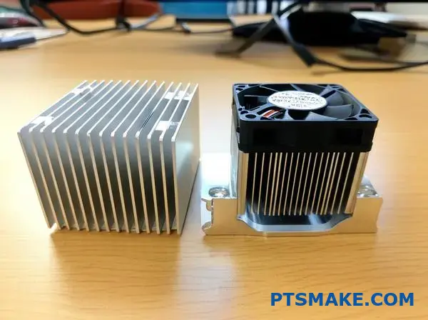
What distinguishes a passive from an active heat sink?
The simplest way to tell them apart is energy. Does the cooling system need external power to work? That’s the core question.
The Self-Sufficient Cooler: Passive Heat Sinks
A passive heat sink operates silently. It uses natural physical processes to dissipate heat. There are no moving parts involved. It’s pure physics at work.
The Power-Assisted Cooler: Active Heat Sinks
Active heat sinks use powered components. Think fans or pumps. This external energy boosts the cooling process significantly.
Here’s a quick breakdown:
| Heat Sink Type | External Energy Input |
|---|---|
| Passive | No |
| Active | Yes (e.g., fans, pumps) |
The choice between active and passive cooling isn’t just about adding a fan. It’s a fundamental design decision. This choice impacts reliability, cost, and performance. In my experience at PTSMAKE, this is a crucial first step.
The Reliability of Simplicity
A passive heat sink is incredibly reliable. With no moving parts, there are fewer points of failure. This is vital for mission-critical applications. Think medical devices or aerospace components where failure is not an option. They rely purely on natural convection2 and radiation to transfer heat away. This makes them silent and maintenance-free.
The Performance of Power
Active systems, however, offer superior cooling. When a component generates a massive amount of heat, natural processes aren’t enough. Adding a fan forces air over the fins, drastically increasing heat dissipation. We see this in high-performance computing and automotive electronics. The trade-off is added complexity, noise, potential failure points, and higher operational costs.
This table highlights the key trade-offs we often discuss with clients.
| Feature | Passive Heat Sink | Active Heat Sink |
|---|---|---|
| Performance | Lower | Higher |
| Reliability | Very High | Moderate |
| Noise Level | Silent | Audible |
| Cost | Lower | Higher |
| Maintenance | None | Required |
The fundamental difference between active and passive heat sinks lies in their use of external power. Passive sinks use natural physics for silent, reliable cooling. Active sinks use fans or pumps for superior performance, introducing complexity and potential failure points.
How are passive heat sinks categorized by manufacturing process?
Choosing the right passive heat sink starts with the manufacturing process. Each method offers a unique balance of cost, performance, and design freedom.
Think of it as a toolkit. You wouldn’t use a hammer to turn a screw.
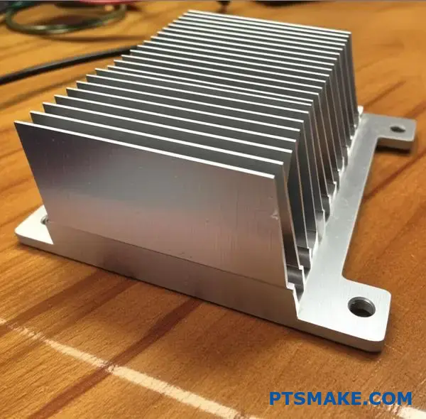
Extrusion: The Workhorse
This is the most common method. Aluminum is pushed through a die to create a long, finned profile. It’s cost-effective for high volumes.
Stamping: Simple and Fast
For low-power applications, stamped heat sinks are perfect. Thin sheets of metal are stamped into shape.
| Process | Typical Cost | Common Material |
|---|---|---|
| Extrusion | Low to Medium | Aluminum |
| Stamping | Very Low | Aluminum, Copper |
This choice directly impacts your project’s budget and thermal performance.
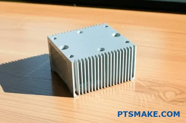
Let’s explore the key manufacturing methods in more detail. The process determines everything from fin density to the final shape of your passive heat sink. At PTSMAKE, we often handle secondary machining on these parts, so we see the pros and cons firsthand.
Forging for Complexity
Forging uses high pressure to shape a block of metal. This creates heat sinks with complex 3D pin fin arrays. It improves thermal performance over extrusion but costs more.
Skiving and Bonded Fins for High Performance
Skiving shaves thin fins from a solid block of copper or aluminum. This allows for very high fin densities. Bonded fin heat sinks attach individual fins to a base. This method is great for large or custom designs. It allows for a copper base with aluminum fins, blending performance and weight. The manufacturing method must align with your thermal needs and the aspect ratio3 your design can tolerate.
Here is a quick comparison of these advanced methods.
| Method | Best For | Design Constraint | Relative Cost |
|---|---|---|---|
| Forging | 3D Airflow | Draft Angles | Medium |
| Skiving | High Fin Density | Material Softness | High |
| Bonded Fin | Large Sizes | Assembly Tolerances | High |
Understanding these trade-offs is crucial. It prevents over-engineering and helps you manage costs effectively from the start. Our role is to provide the precision machining needed to perfect these components.
Selecting the right manufacturing process involves balancing thermal performance, design complexity, and budget. Each method, from simple stamping to advanced skiving, offers distinct advantages and constraints that directly impact your final product’s efficiency and cost.
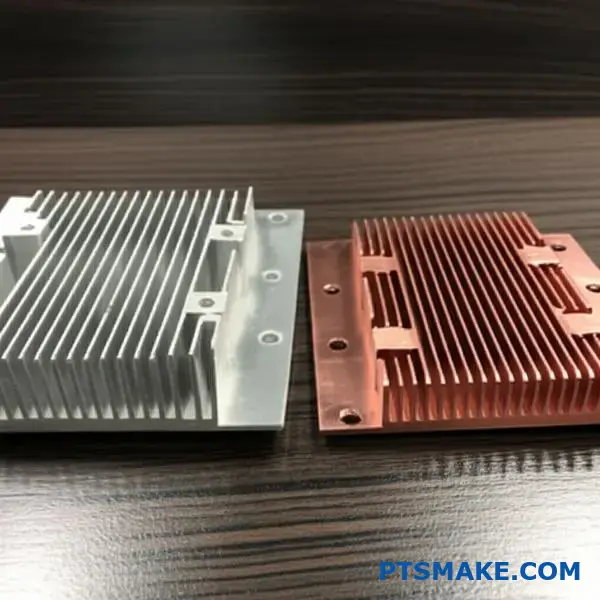
Beyond aluminum, what other materials are used and why?
While aluminum is a versatile workhorse, it’s not always the best fit. For high-performance needs, other materials step in. Copper is a primary alternative.
It offers far superior thermal conductivity. This makes it excellent for demanding applications.
However, this performance comes with trade-offs. Copper is significantly heavier and more expensive. It also presents different challenges in the manufacturing process. A copper passive heat sink is a specialized solution.
| Feature | Aluminum (6061) | Copper (C110) |
|---|---|---|
| Thermal Conductivity | ~167 W/mK | ~385 W/mK |
| Relative Density | 1.0 | 3.3 |
| Relative Cost | 1.0 | ~2.5 – 3.5 |

Deciding between aluminum and copper is a classic engineering trade-off. It balances thermal performance against budget and weight constraints. In our projects at PTSMAKE, we often see copper specified for high-power processors or laser diodes where removing heat quickly is critical.
But the material landscape doesn’t stop at copper. For truly cutting-edge applications, we look towards even more advanced options.
Advanced Thermal Solutions
The Rise of Graphite
Graphite is a game-changer for thermal management in compact devices. It’s incredibly lightweight and has fantastic heat-spreading capabilities.
Its unique anisotropic properties4 are key. This means it conducts heat exceptionally well along its planes but poorly through them. This allows engineers to direct heat away from sensitive components laterally, which is perfect for thin profiles like smartphones or tablets.
| Material | Key Advantage | Best Use Case |
|---|---|---|
| Copper | High bulk conductivity | Power electronics, CPU coolers |
| Graphite | Excellent in-plane spreading | Thin electronics, battery cooling |
These advanced materials aren’t just drop-in replacements. They solve specific problems that common metals can’t. Selecting the right one requires a clear understanding of the thermal challenge and manufacturing possibilities.
Copper provides superior thermal conductivity compared to aluminum but comes with increased weight and cost. Advanced materials like graphite offer lightweight, high-performance heat spreading for specialized, space-constrained applications, highlighting the importance of material selection in thermal design.
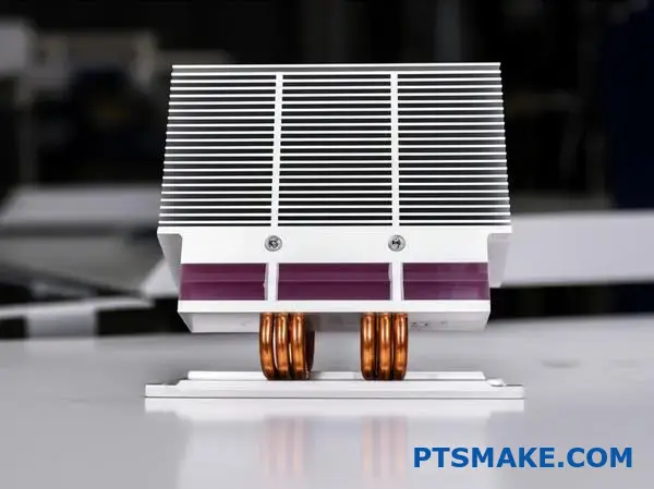
The Core Principle: Two-Phase Heat Transfer
Vapor chambers and heat pipes aren’t just empty metal containers. They are sophisticated two-phase heat transfer devices. Their secret lies in a clever use of physics.
A Self-Contained Cycle
Inside, a small amount of fluid constantly cycles. It changes from liquid to vapor and back again. This cycle moves heat with incredible efficiency. It’s a continuous, passive process.
Like a Thermal Superconductor
This process transfers large amounts of heat. It does so with a very small temperature difference. This makes them act like "thermal superconductors" in passive heat sink designs.
| Phase | Role in Heat Transfer | Location in Device |
|---|---|---|
| Liquid | Absorbs heat, becomes vapor | Evaporator (Hot Side) |
| Vapor | Moves heat quickly | Core/Chamber |
| Liquid | Releases heat, condenses | Condenser (Cool Side) |
The Science of Phase Change
At the heart of this technology is a simple principle. When a liquid turns into a vapor, it absorbs a massive amount of energy. This happens without the liquid getting any hotter. This energy is called the latent heat of vaporization5.
This stored energy travels with the vapor. It moves from the hot spot to a cooler area. When the vapor cools and condenses back into a liquid, it releases all that stored heat. This process is far more effective at moving thermal energy than simple conduction through a solid material.
Why It’s More Efficient
Think about boiling water. You can add a lot of heat to a pot of boiling water, but its temperature stays at 100°C. That energy is used to create steam. Heat pipes and vapor chambers harness this exact effect in a closed loop. They are essentially passive heat engines.
This makes them ideal for high-power density applications. They quickly pull heat away from a concentrated source.
Performance Comparison
In many of our projects at PTSMAKE, we’ve seen the difference. The effective thermal conductivity can be orders of magnitude higher than solid copper or aluminum.
| Material | Effective Thermal Conductivity (W/m·K) |
|---|---|
| Copper | ~400 |
| Aluminum | ~235 |
| Heat Pipe / Vapor Chamber | 5,000 – 200,000+ |
Vapor chambers and heat pipes use a liquid-to-vapor phase change. This allows them to transfer significant heat over a distance with minimal temperature drop. This high efficiency makes them function as "thermal superconductors" in advanced passive cooling solutions.
What are the purposes of anodizing or painting a heat sink?
Choosing a finish for a heat sink isn’t just about looks. The choice is often between anodizing and painting. Each offers very different benefits.
Anodizing is a complex process. It provides protection and insulation. Painting is more straightforward. Its main job is boosting heat radiation.
Let’s compare them directly.
| Feature | Anodizing | Painting |
|---|---|---|
| Primary Goal | Protection & Insulation | Emissivity |
| Process | Electrochemical | Application of coat |
| Durability | High | Varies by paint |
This helps clarify which treatment is best for your specific application.
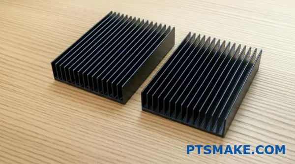
Anodizing: More Than a Surface Coat
Anodizing is not just a layer on top. It is an electrochemical process6 that converts the metal surface. It creates a very hard, non-conductive aluminum oxide layer. This is vital for a passive heat sink used near sensitive electronic components.
This oxide layer provides excellent corrosion resistance. It protects the heat sink from environmental factors. It also significantly increases the surface emissivity. This boost allows the heat sink to radiate heat away more effectively into the surrounding air.
Painting: A Targeted Approach
Painting is a simpler surface application. Special thermal paints are designed with high emissivity. This is their main purpose. They help the heat sink radiate heat more effectively.
However, paint can also act as an insulating layer. If applied too thickly, it can hinder heat transfer. This is a critical factor we consider at PTSMAKE. We ensure the application optimizes radiation without impeding convection.
Here is a more detailed comparison based on our project experience.
| Aspect | Anodizing | Painting |
|---|---|---|
| Electrical Insulation | Excellent | Poor (unless special paint) |
| Corrosion Resistance | Excellent | Good |
| Thermal Impact | Boosts radiation, minimal impact on convection | Boosts radiation, can hinder convection if thick |
| Best For | Harsh environments, electrical isolation needed | Cost-effective emissivity boost |
In short, anodizing provides robust benefits: corrosion resistance, electrical insulation, and improved emissivity. Painting is a targeted, often more economical, choice for enhancing thermal radiation. Your final decision depends on the application’s environment and electrical requirements.
How does enclosure design impact a heat sink’s effectiveness?
A heat sink is not an island. Its performance is tied to the entire system. You must think about the enclosure as part of the thermal solution. Without proper airflow, even the best heat sink will fail.
The Role of Enclosure Venting
Venting is your most powerful tool. It creates a path for cool air to enter and hot air to exit. This constant exchange is vital for effective cooling. Without it, the heat has nowhere to go.
A Path for Airflow
Think of airflow like a highway. Vents are the on-ramps and off-ramps. Block them, and you create a traffic jam of hot air. This stalls the cooling process completely.
A well-designed system considers vent placement carefully.
| Feature | Vented Enclosure | Sealed Enclosure |
|---|---|---|
| Primary Cooling | Convection | Radiation |
| Airflow | High | Minimal/None |
| Heat Sink Efficiency | Optimal | Severely Reduced |
| Internal Temp | Lower | Higher |
Thinking at a system level is key. In past projects at PTSMAKE, we’ve seen designs fail not because of the heat sink, but because the enclosure trapped hot air. The heat sink became saturated, unable to dissipate more heat.
Convection: The Dominant Cooling Force
For most applications, convection is the main way a heat sink works. It relies on air moving across the fins, carrying heat away. A vented enclosure enables this process by providing a steady supply of cooler, ambient air.
What Happens in a Sealed Box?
When you seal the enclosure, you cut off the air supply. The air inside heats up and stagnates. This effectively stops convective heat transfer7 in its tracks. The heat sink can no longer efficiently shed its thermal load to the surrounding air because that air is already hot.
This is especially critical for a passive heat sink, which relies entirely on natural convection.
The Shift to Radiation
In a sealed box, the primary method of heat transfer becomes radiation. The heat sink radiates thermal energy to the inner walls of the enclosure. This is a much less efficient process compared to convection.
| Cooling Mode | Vented Enclosure | Sealed Enclosure |
|---|---|---|
| Convection | Dominant (70-95%) | Minimal (<10%) |
| Radiation | Secondary (5-30%) | Dominant (>90%) |
| Conduction | Varies by contact | Varies by contact |
Our internal testing confirms that a sealed design can reduce a heat sink’s performance by over 50%. This forces engineers to use much larger, more expensive solutions to compensate.
System-level thinking prevents costly design mistakes. A well-vented enclosure is critical for convection, ensuring your heat sink performs as intended. Sealed boxes cripple this process, shifting reliance to less efficient radiation and compromising thermal management.
How do you choose between aluminum 6063 and copper 1100?
Choosing between Aluminum 6063 and Copper 1100 is a classic engineering balancing act. It isn’t about which metal is simply "better." The real question is which is right for your project’s specific needs.
You must weigh four critical factors. These are thermal performance, weight, overall cost, and how easily we can shape it. This analysis guides your final decision.
Core Trade-Offs
Let’s look at a quick comparison.
| Feature | Aluminum 6063 | Copper 1100 |
|---|---|---|
| Thermal Conductivity | Good (~200 W/mK) | Excellent (~385 W/mK) |
| Density | Low (~2.7 g/cm³) | High (~8.9 g/cm³) |
| Cost | Low | High |
| Machinability | Excellent | Good |
This table highlights the fundamental trade-offs you face.
Let’s break down these trade-offs with a practical example. Consider designing a custom passive heat sink for an electronics project. This is a common challenge we tackle at PTSMAKE.
Performance vs. Practicality
Copper 1100’s superior thermal conductivity is its main advantage. It pulls heat away from sensitive components nearly twice as fast as aluminum. This is crucial for high-power applications where every degree matters.
However, this performance comes at a price. Copper is about three times heavier and significantly more expensive. For a portable device or a large-scale production run, these factors can quickly make copper impractical.
Machinability and Design
Aluminum 6063 is fantastic to machine. Its properties allow for creating complex fin designs efficiently, which maximizes surface area. Copper 1100, being softer, can sometimes be "gummy" during machining. This requires specific tooling and can slightly slow down production.
The real goal is to lower the total Thermal Resistance8 from the chip to the surrounding air. A well-designed aluminum sink can often outperform a basic copper one.
| Application Scenario | Better Choice | Justification |
|---|---|---|
| High-Power CPU Cooler | Copper 1100 | Maximum heat dissipation is the priority. |
| LED Lighting Enclosure | Aluminum 6063 | Good thermal management, lightweight, and cost-effective. |
| Portable Electronics | Aluminum 6063 | Weight and cost are major constraints. |
| Server Rack Components | Either | Depends on specific thermal load vs. budget. |
The decision isn’t always clear-cut. It requires a careful look at your project’s unique priorities.
The choice is a balance of performance versus budget and physical constraints. Copper excels in thermal management, while aluminum offers a superb, cost-effective, and lightweight solution that is ideal for a wider range of applications.
How do you determine the appropriate heat sink base thickness?
Finding the right base thickness is a balancing act. It’s about thermal performance versus resource cost.
A thicker base helps spread heat very well. This is crucial for small, high-power components. It prevents hot spots.
However, more thickness means more material. This adds weight and increases the cost of your passive heat sink.
The Core Trade-Off
| Feature | Thinner Base | Thicker Base |
|---|---|---|
| Heat Spreading | Less effective | More effective |
| Weight | Lighter | Heavier |
| Material Cost | Lower | Higher |
| Ideal Use | Large, low-power | Small, high-power |
The goal is to avoid over-engineering. Adding thickness gives you better heat spreading, but only up to a certain point.
Eventually, you reach a point of diminishing returns9. Each extra millimeter of thickness provides less and less thermal benefit. The cost and weight, however, keep increasing.
So how do you find that sweet spot?
Using Simulation to Optimize
Simulation is our best tool here. Using software like Finite Element Analysis (FEA), we can model thermal performance accurately. This lets us test different thicknesses digitally before any metal is cut.
We can pinpoint the exact thickness where performance gains start to level off. This approach, which we often use in projects at PTSMAKE, avoids unnecessary material usage and cost for our clients. It helps us make data-driven decisions.
Cost vs. Performance Analysis
The table below, based on our internal tests, shows how performance gains shrink while costs rise.
| Base Thickness | Thermal Resistance (°C/W) | Relative Cost |
|---|---|---|
| 3 mm | 0.85 | 100% |
| 5 mm | 0.70 | 167% |
| 7 mm | 0.65 | 233% |
| 9 mm | 0.63 | 300% |
Notice the small improvement from 7mm to 9mm. This is where the extra cost is often not worth the marginal gain.
Choosing the right heat sink base thickness is a critical balance. You need enough material for effective heat spreading without adding excessive weight or cost. Simulation helps find the optimal point where performance justifies the resources used.
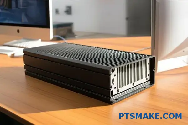
How would you design a heat sink for a sealed, fanless enclosure?
Let’s tackle a complex, real-world problem. Imagine designing a passive heat sink for sensitive electronics. These components are housed in a completely sealed, fanless enclosure.
This unit will operate outdoors. It must withstand the elements. Heat becomes the primary engineering challenge.
The Constraint-Driven Problem
The core issue is the sealed environment. There’s no internal airflow to help. Heat has nowhere to go easily. We must rely on passive methods.
The design must work within several key limits.
| Constraint | Design Implication |
|---|---|
| Sealed Enclosure | No conventional convection cooling inside. |
| Sensitive Electronics | A very tight operating temperature window. |
| Outdoor Use | Must account for solar radiation and ambient temperature shifts. |
| Fanless Requirement | Reliability is key; no moving parts allowed. |
This scenario forces us to rethink standard cooling. We must integrate multiple heat transfer concepts. The solution requires a clever, multi-stage approach.
In a sealed system, we must ignore internal convection. It’s simply not a factor. The entire strategy shifts to a two-step process. First, move heat from the source to the enclosure’s inner walls. Second, move that heat from the enclosure to the outside world.
Stage 1: Maximizing Internal Radiation
The primary mechanism inside the box is radiation. The hot component radiates thermal energy. This energy travels to the cooler interior walls of the enclosure.
To make this effective, surface finish is critical. A high emissivity10 coating on both the component and the inner walls is crucial. In past projects at PTSMAKE, we’ve seen anodizing or specific paints increase heat transfer significantly.
Stage 2: The Enclosure as the Final Radiator
Once the heat reaches the enclosure walls via conduction and radiation, the enclosure itself becomes the heat sink. Its job is to dissipate this energy to the surrounding environment.
This happens through two external paths.
| Heat Transfer Path | Inside the Enclosure | Outside the Enclosure |
|---|---|---|
| Conduction | Component -> Mounting Points -> Enclosure | – |
| Convection | Negligible (trapped air) | Enclosure Surface -> Ambient Air |
| Radiation | Component -> Inner Enclosure Walls | Enclosure Surface -> Surroundings |
Maximizing the external surface area is paramount. We often machine external fins directly into the enclosure. This dramatically increases the area for both natural convection and radiation to the environment. Aluminum is an excellent material choice here.
This problem requires a shift in thinking. The solution de-emphasizes internal convection, focusing instead on a two-stage process: maximizing internal radiation to the walls, then maximizing external dissipation from the enclosure itself. This makes the entire case the passive heat sink.
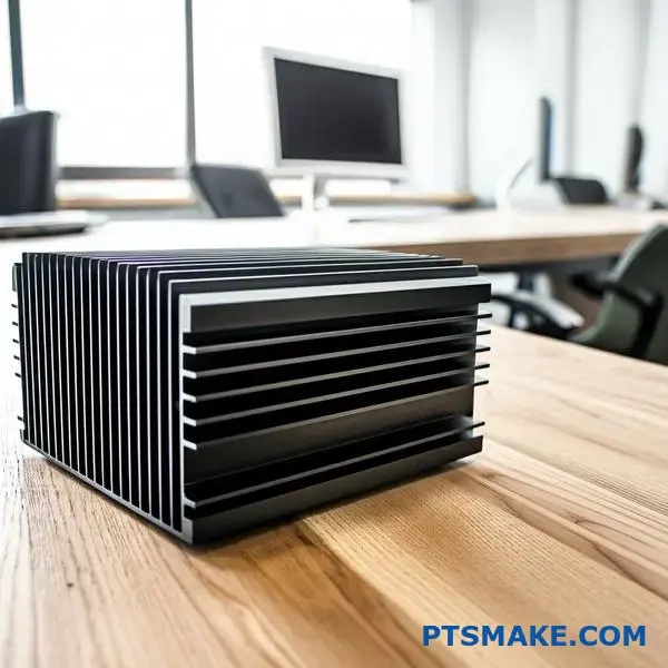
What strategies are used for passively cooling high power density components?
Simple aluminum extrusions are workhorses for thermal management. However, they have clear limitations. They often fail when dealing with high power density components.
The intense heat from a small source creates a bottleneck. A standard extrusion can’t spread this thermal load fast enough. This is where we must consider more advanced passive heat sink technologies.
| Cooling Method | Heat Spreading | Surface Area |
|---|---|---|
| Extrusion | Limited | Good |
| Heat Pipe/Vapor Chamber | Excellent | Varies |
| Skived Fin | Good | Excellent |
These advanced options tackle the core challenges of high-density cooling.
Knowing when to abandon simple extrusions is key. In past projects at PTSMAKE, this decision point is often when a heat source becomes too concentrated. The base of a standard heat sink just can’t keep up.
Advanced Heat Spreading Solutions
Heat pipes and vapor chambers are game-changers for heat spreading. They are not just solid metal. They utilize a process of vaporization11 and condensation of a working fluid. This process moves heat with incredible efficiency, often hundreds of times better than solid copper.
Vapor Chambers for Hot Spots
Vapor chambers are essentially flat heat pipes. They are perfect for spreading heat from a small, intense source, like a CPU, over a much larger area. This creates a more uniform temperature at the base of the fin stack.
Heat Pipes for Transport
Heat pipes are ideal for moving heat from a component to a remote fin stack. This offers great design flexibility in cramped enclosures.
Maximizing Surface Area
Sometimes, the challenge is dissipating heat to the air. Skived fin technology shines here. A single block of copper or aluminum is precisely shaved to create very thin, dense fins. This technique dramatically increases the surface area available for convection.
| Technology | Primary Function | Common Use Case |
|---|---|---|
| Vapor Chamber | Heat Spreading | High-power processors (CPUs, GPUs) |
| Heat Pipe | Heat Transport | Moving heat in laptops, servers |
| Skived Fin | Heat Dissipation | Compact, high-performance systems |
When standard extrusions reach their limit, advanced solutions are necessary. Heat pipes and vapor chambers excel at spreading heat, while skived fins maximize dissipation. These technologies are crucial for cooling high-power components effectively.
Your passively cooled product is overheating. What is your troubleshooting process?
When a product overheats, don’t guess. A systematic workflow saves time and money. Start with the basics before disassembling anything.
This process ensures you cover all potential root causes methodically. It moves from external factors to internal components.
Initial Diagnostic Checklist
| Step | Action | Purpose |
|---|---|---|
| 1 | Verify Power | Check if power draw is within specs. |
| 2 | Check Environment | Confirm ambient temperature is normal. |
| 3 | Inspect Vents | Ensure no airflow blockages. |
This structured approach helps isolate the problem quickly and efficiently. A good passive heat sink design can fail if these basics are overlooked.
A solid diagnostic plan starts with easily verifiable data. Overlooking these fundamentals can lead you down the wrong path. In past projects at PTSMAKE, we’ve found that starting with simple checks often solves the issue without complex teardowns.
Verifying Power and Environment
First, confirm the power consumption. Is the device drawing more power than the thermal solution was designed for? Next, check the ambient temperature. A product tested in a 20°C lab will behave differently in a 35°C environment. These are simple but crucial first steps.
Physical and Virtual Cross-Checks
Then, move to physical inspection. We often see issues with the Thermal Interface Material12 (TIM). Was it applied correctly? Is the mounting pressure even and sufficient? An improper application creates air gaps that kill thermal performance. Also, ensure all vents are completely clear. A small obstruction can have a large impact.
Finally, compare your findings to the original design simulations.
| Parameter | Simulation Value | Measured Value |
|---|---|---|
| CPU Temp | 75°C | 90°C |
| Ambient Temp | 22°C | 30°C |
| Power Draw | 15W | 18W |
This comparison highlights discrepancies. It points you directly to the source of the extra heat or the underperforming cooling component.
This systematic workflow transforms troubleshooting from guesswork into a clear, repeatable process. It logically moves from simple environmental checks to detailed physical and data-driven analysis, ensuring efficient and accurate problem resolution for your passively cooled device.
Can a passive heat sink generate noise, and how?
It seems impossible. A solid piece of metal with no moving parts should be silent. But that’s not always true.
Under specific conditions, a passive heat sink can produce a high-pitched hum or "sing." This is a real acoustic phenomenon. It’s caused by air flowing across its fins at just the right speed. This effect is often called fin singing or aeolian tones. It’s an interesting problem we sometimes solve for clients.
This noise is not random. It happens when airflow creates a predictable pattern of swirling air, or vortices, on either side of a fin.
This repeating pattern is known as the Kármán vortex street13. It creates alternating pressure, pushing and pulling on the fin. This forces the fin to vibrate.
If this vibration matches the fin’s natural resonant frequency, it produces an audible sound. The process is similar to how blowing over a bottle’s opening creates a tone. This issue is more common in environments with consistent, high-volume airflow.
Fortunately, we can engineer solutions for this. At PTSMAKE, precision CNC machining allows us to create complex fin geometries that eliminate this noise. We’ve found that small changes can make a huge difference.
| Prevention Method | How It Works | Key Advantage |
|---|---|---|
| Varying Fin Geometry | Changes the thickness or spacing of fins. | Disrupts the resonant frequency, stopping the vibration. |
| Adding Dampers | Small polymer inserts are placed between fins. | Absorbs vibrational energy, muting any potential sound. |
| Altering Fin Edges | Modifying the leading edge to be less sharp. | Smooths airflow and reduces the formation of strong vortices. |
Through careful design and precise manufacturing, we can ensure a passive heat sink remains completely silent, even in challenging airflow conditions.
A passive heat sink can generate a high-pitched noise called ‘fin singing.’ It’s caused by airflow creating vibrations that match the fin’s resonant frequency. This can be prevented through smart design choices, like altering fin geometry or adding vibration dampers.
Unlock Superior Passive Heat Sink Solutions With PTSMAKE
Ready to elevate your project with expertly designed passive heat sinks? Contact PTSMAKE today for a fast, customized quote and experience the reliability, precision, and service trusted by global innovators. Let’s turn your thermal management challenges into your next competitive advantage—send your inquiry now!

Explore a deeper explanation of entropy and its critical role in thermal management for engineering applications. ↩
Understand this key heat transfer mechanism to improve your thermal management designs. ↩
Understand how this crucial design ratio affects thermal efficiency. ↩
Learn how a material’s directional properties can be leveraged for advanced thermal management. ↩
Discover the physics that allows these devices to transfer heat so effectively. ↩
Understand how this process transforms metal surfaces for superior durability and electrical insulation. ↩
Learn how heat moves through air and fluids to improve your thermal design strategy. ↩
Learn how this key metric impacts your heat sink’s real-world performance. ↩
Learn how this principle helps prevent over-engineering and saves you money on manufacturing projects. ↩
Discover how this surface property is essential for maximizing heat transfer in fanless designs. ↩
Discover the core principle behind how these advanced thermal solutions rapidly transfer heat away from critical components. ↩
Learn how TIM choice and application can make or break your product’s thermal management. ↩
Learn more about the physics behind this airflow pattern and its effects on engineering design. ↩