Are you struggling with heat management in high-power systems where standard cooling solutions simply can’t handle the thermal load? Large heat sinks become critical when dealing with power levels exceeding 100W, but selecting the wrong design or manufacturing approach can lead to system failures, costly redesigns, and missed project deadlines.
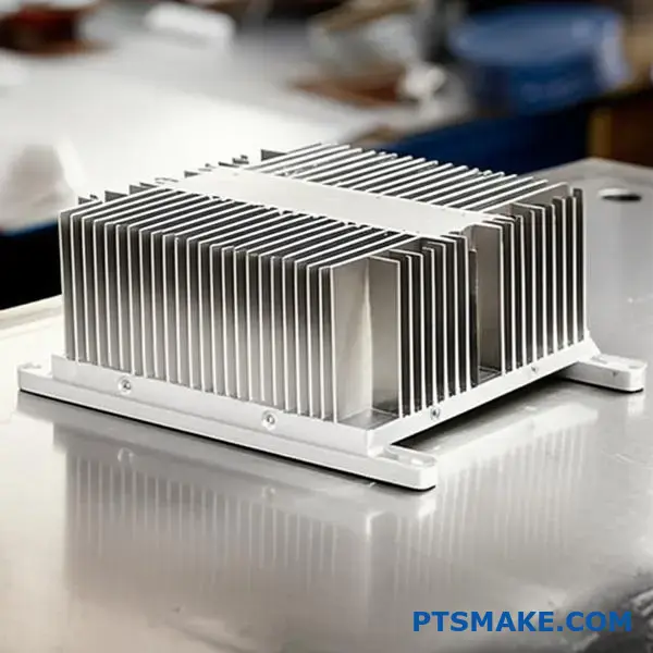
Large heat sinks are specialized thermal management solutions designed for high-power applications typically exceeding 100W, characterized by their substantial thermal mass, advanced manufacturing processes like extrusion or CNC machining, and integration requirements that go far beyond standard electronics cooling.
The challenge isn’t just about size – it’s about understanding which manufacturing process, mounting mechanism, and cooling approach will deliver reliable performance for your specific application. I’ll walk you through the key classifications and design considerations that separate successful large heat sink implementations from problematic ones.
What defines a heat sink as ‘large’ beyond physical size?
When we talk about a large heat sink, it’s easy to picture a massive block of metal. But physical size is only part of the story. The true definition lies in its thermal performance capabilities.
More Than Just a Number
A heat sink’s primary job is dissipating heat. A "large" one is typically designed for high-power applications, often handling more than 100 watts of thermal energy.
Key Performance Indicators
This moves beyond simple component cooling. It becomes about managing the thermal load of an entire system, ensuring reliability under intense operational stress.
| Feature | Standard Heat Sink | Large Heat Sink |
|---|---|---|
| Power Level | Typically < 100W | Often > 100W |
| Primary Goal | Component Cooling | System-level Thermal Management |
The Physics of High-Performance Cooling
A key factor distinguishing a large heat sink is its thermal mass. This is the ability of the heat sink to absorb a significant amount of heat energy without a rapid increase in its own temperature. This is crucial for handling sudden power spikes.
It provides a buffer, smoothing out temperature fluctuations and protecting sensitive electronics. This is a very different challenge from cooling a standard desktop CPU.
Performance Metrics
The effectiveness of a heat sink is often measured by its thermal resistance1. A lower value indicates better performance, meaning heat can be transferred away from the source more efficiently. In large-scale applications, minimizing this value is a primary design goal. At PTSMAKE, we focus on designs that optimize this.
Demanding Applications
Industries requiring robust thermal solutions drive the need for these specialized heat sinks. They ensure both performance and longevity in critical systems.
| Application | Typical Power Dissipation | Cooling Challenge |
|---|---|---|
| Data Center Servers | 150W – 500W per CPU | High density, constant load |
| Industrial VFDs | 200W – 1000W+ | Harsh environments, reliability |
| High-Power LEDs | 100W – 300W | Maintaining light quality and lifespan |
A "large" heat sink is defined by its ability to manage high thermal loads (>100W) and its significant thermal mass. Its design is driven by the demanding requirements of specific industrial applications, moving far beyond simple physical dimensions to focus on critical performance metrics.
Which manufacturing processes are key to large heat sink fabrication?
Selecting the right process for a large heat sink is crucial. Your choice impacts performance, cost, and lead time. The primary methods each have their place. It all depends on your specific thermal and design needs.
Common Fabrication Methods
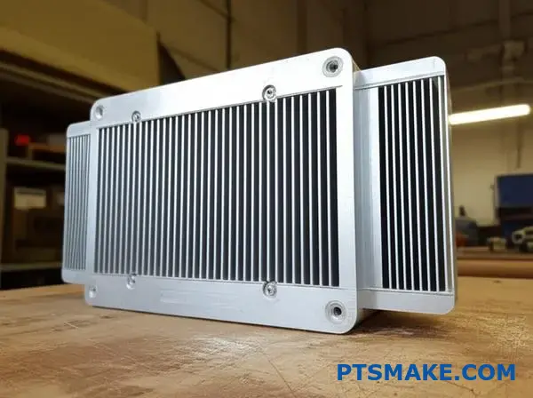
Extrusion is great for high-volume production. Bonded fin and skived fin methods allow for high fin density. CNC machining offers ultimate design freedom for complex shapes.
| Process | Best For | Typical Scale |
|---|---|---|
| Extrusion | High Volume, Simple Profiles | Medium to Large |
| Bonded Fin | High Fin Density, Dissimilar Metals | Large to Very Large |
| Skived Fin | Very High Fin Density, Single Block | Medium to Large |
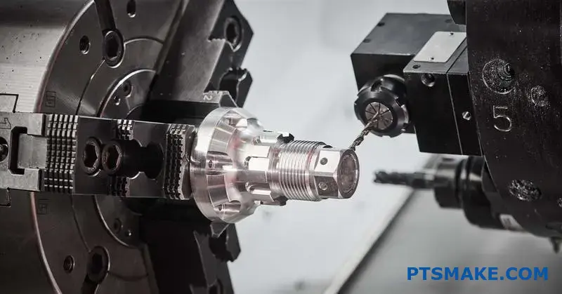
| CNC Machining | Complex Geometries, Prototypes | Any, especially Large |
Choosing a manufacturing process isn’t just about the final part. It’s a strategic decision balancing performance, cost, and complexity. Each method has distinct advantages and limitations you must consider early in the design phase.
Comparing Key Processes
At PTSMAKE, we guide clients through this decision daily. For example, extrusion is often the most cost-effective option for simpler, large-scale projects. However, its design capabilities are limited by the extrusion die.
Bonded fin heat sinks offer more flexibility. They allow us to use different materials for the base and fins. This can optimize thermal performance. But, the bonding process introduces an extra interface. This interface can impact the overall thermal resistance2 of the final product.
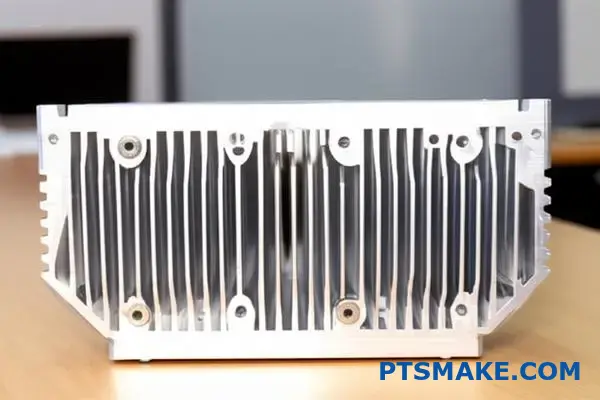
Skived fin and CNC machining provide the highest performance for demanding applications. Skiving creates very thin, dense fins from a single block of metal. This avoids any interface issues. CNC machining allows for almost any geometry, perfect for unique or integrated cooling solutions.
Process Selection Trade-offs
| Method | Thermal Performance | Design Flexibility | Unit Cost (High Vol.) |
|---|---|---|---|
| Extrusion | Good | Low | Low |
| Bonded Fin | Very Good | High | Medium |
| Skived Fin | Excellent | Medium | High |
| CNC Machining | Excellent | Very High | High |
Understanding these trade-offs is key. We focus on finding the sweet spot where the manufacturing process aligns perfectly with both your technical requirements and your budget for a large heat sink project.
The right manufacturing method—extrusion, bonded fin, skived fin, or CNC machining—depends on your project’s specific needs. Consider factors like thermal performance, design complexity, volume, and budget to make the best choice for your large heat sink.
What are the main categories of large air-cooled heat sinks?
The manufacturing process is key. It defines a heat sink’s performance and cost. Each method offers unique advantages for different thermal challenges. We mainly see four types in the industry.
Core Manufacturing Methods
These include extruded, skived, bonded fin, and folded fin designs. Understanding them helps you choose the right solution for your project. This choice impacts everything from cooling to cost.
Quick Comparison
Here is a basic overview of these common types.
| Manufacturing Method | Typical Performance | Cost Level |
|---|---|---|
| Extruded | Low to Medium | Low |
| Skived | Medium to High | Medium |
| Bonded Fin | High | High |
| Folded Fin | Medium | Medium-High |
Let’s look closer at these methods. Each has its place in thermal management. The choice really depends on your specific needs for a large heat sink.
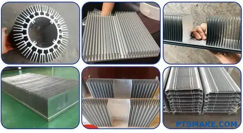
Extruded and Skived Fins
Extruded heat sinks are very common. They are made by pushing aluminum through a die. This process is cost-effective. However, it limits the fin height and spacing, which can affect cooling power.
Skived fin heat sinks offer better performance. We create them by slicing thin fins from a solid block of copper or aluminum. This method allows for higher fin density without any interface material, improving heat transfer.
Bonded and Folded Fins
For high-power needs, bonded fins are excellent. We machine a base and then attach individual fins. At PTSMAKE, our CNC machining skills ensure a perfect thermal bond. This allows for very tall fins and even mixed-metal designs.
Folded fin heat sinks are lightweight and efficient. A sheet of metal is stamped and folded. It is then brazed to a baseplate. This technique creates a large surface area, which helps lower the overall thermal resistance3 of the assembly.
Here’s a more detailed breakdown.
| Heat Sink Type | Best For | Fin Density | Material Options |
|---|---|---|---|
| Extruded | Low-cost, standard power | Low | Aluminum |
| Skived | High thermal conductivity | High | Copper, Aluminum |
| Bonded Fin | High power, custom designs | Very High | Mixed metals |
| Folded Fin | Lightweight needs | High | Aluminum, Copper |
Choosing the right large heat sink means matching the manufacturing method to your application’s thermal, budget, and space requirements. Each type offers a distinct balance of performance and cost, ensuring an optimal solution is always available for your needs.
How are large liquid cooling systems structured and categorized?
Large liquid cooling systems all share a core structure. Think of it as a circulatory system for heat.
It efficiently moves thermal energy away. This keeps high-power electronics running cool and stable.
Let’s break down the essential components and classifications.
The Core Components of a Liquid Cooling Loop
Every loop has four key parts working together.
- Cold Plate: Sits directly on the heat source.
- Pump: This is the heart, circulating the coolant.
- Radiator: A large heat sink that releases heat into the air.
- Tubing: Connects everything into a sealed loop.
Key System Categories
We primarily categorize these systems by how they operate.
| Category | Key Feature |
|---|---|
| Active Cooling | Uses a pump to actively move liquid. |
| Passive Cooling | Relies on natural convection, no pump. |
Direct-to-Chip vs. Immersion Cooling: A Closer Look
Direct-to-Chip (DTC) cooling is about precision. Cold plates, often complex CNC machined parts, mount directly onto hot components like CPUs or GPUs.
This targeted approach is very efficient. The fit must be perfect for optimal heat transfer, a detail we obsess over at PTSMAKE.
Immersion cooling is a completely different philosophy. It submerges entire server components in a non-conductive, or dielectric fluid4. This method offers total, uniform cooling coverage.
Choosing the Right Approach: It’s About Trade-offs
The best choice always depends on specific application needs. There’s no single right answer for every situation.
In past projects, we’ve helped clients weigh these options. It’s a balance of performance, long-term maintenance, and of course, budget.
Here’s a simple breakdown to help compare them.
| Feature | Direct-to-Chip (DTC) | Immersion Cooling |
|---|---|---|
| Efficiency | Highly efficient for targeted hot spots. | Extremely effective, uniform cooling. |
| Complexity | Simpler to install and maintain. | More complex infrastructure required. |
| Scalability | Easy to scale per component. | Better for large, dense server racks. |
| Material Cost | Lower initial hardware cost. | High cost for specialized fluids. |
Understanding a system means knowing its parts: cold plate, pump, radiator, and tubing. Systems are categorized as active or passive and by method, like direct-to-chip or full immersion. Each design offers unique trade-offs in efficiency, complexity, and cost.
How are large heat sinks classified by their intended application?
A large heat sink is never a universal component. Its design is fundamentally shaped by its intended application. Different electronics produce heat in very different ways.
Therefore, the thermal solution must be tailored to the specific challenge. A design for an industrial power supply will fail on a server CPU.
Key Application Drivers
Understanding these distinctions is crucial for effective thermal management. Each application presents unique requirements for size, shape, and material.
| Application Area | Primary Design Focus |
|---|---|
| IGBT / Power Electronics | Handling High Current & Voltage |
| High-Power LED Arrays | Broad, Even Heat Spreading |
| Server CPU / GPU | Intense, Concentrated Heat Removal |
| Industrial Power Supply | Long-Term Reliability |
Unique Thermal Challenges for Each Application
Delving deeper, we see how specific needs drive distinct designs. It’s not just about dissipating heat; it’s about how and where that heat is generated. In our past projects at PTSMAKE, we’ve seen how overlooking these details leads to failure.
IGBTs and Power Electronics
These components manage massive electrical loads. Their heat sinks must be robust, often with thick fins to handle high thermal cycles. Electrical isolation is also a major safety and performance consideration in the design.
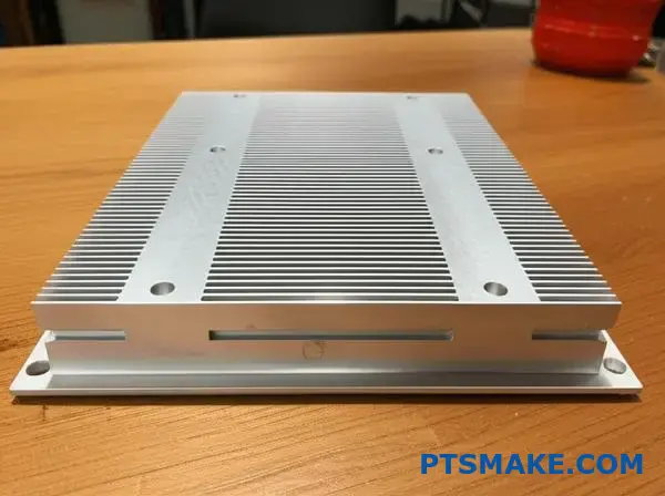
High-Power LED Arrays
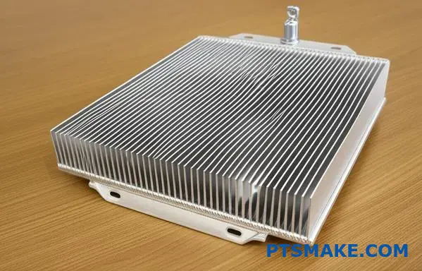
Here, heat is spread over a large surface area. The primary goal is uniform cooling to maintain light quality and prevent premature aging. This often requires a large heat sink with a very flat baseplate.
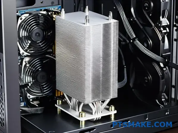
Server CPUs and GPUs
This is a game of extremes. The Heat Flux Density5 is incredibly high, demanding aggressive cooling in a very small area. Designs frequently incorporate heat pipes or vapor chambers to pull heat away from the chip to a large fin stack.
Industrial Power Supplies
Reliability is the top priority. These systems often rely on passive cooling to operate for years without maintenance. This means larger fin spacing for effective natural convection and to minimize dust accumulation, a different approach entirely.
Understanding the application’s unique thermal profile is the first step. A heat sink for a CPU is completely different from one for an LED array. The design must match the specific heat load, space, and reliability requirements.
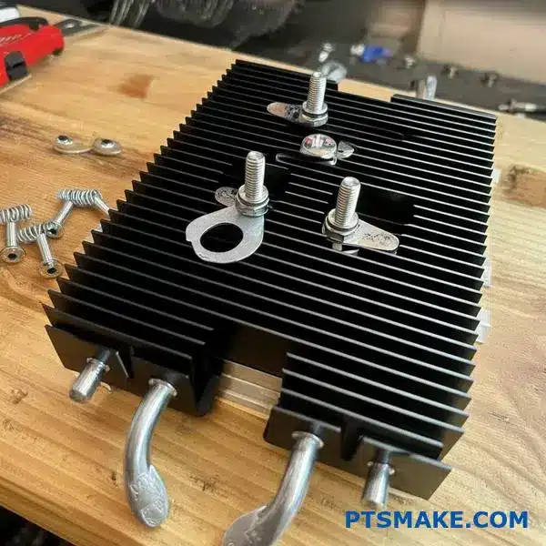
How do mounting mechanisms for large heat sinks vary?
Choosing the right mounting mechanism is critical. It ensures your large heat sink performs optimally. The method impacts everything from thermal transfer to structural integrity.
Common Mounting Methods
Different applications demand different solutions. Each has unique pros and cons.
Push Pins
These offer a quick, tool-free installation. They are often used in less demanding environments.
Screws with Springs
This method provides more consistent pressure. It’s a reliable choice for high-performance needs.
| Method | Installation Speed | Pressure Control | Cost |
|---|---|---|---|
| Push Pins | Very Fast | Low | Low |
| Screws & Springs | Moderate | High | Moderate |
| Chassis Mount | Slow | Very High | High |
This choice directly affects your device’s lifespan.
The Critical Role of Mounting Pressure
Beyond just securing the heatsink, mounting pressure is key. It directly influences the Thermal Interface Material (TIM).
Uneven pressure creates gaps and air pockets. This severely hinders heat transfer. We’ve seen this in past projects at PTSMAKE. Proper pressure ensures a minimal and uniform Bond Line Thickness6.
This thin layer is vital for efficient cooling.
Direct Chassis Mounting
For the heaviest large heat sink applications, this is the best. It bolts the heatsink directly to the system chassis. This provides maximum stability and support.
It also allows for very high, uniform mounting pressure. This is essential for large, high-power components. However, it requires careful design of both the heatsink and the chassis.
| Pressure Factor | Impact on TIM | Consequence of Error |
|---|---|---|
| Too Low | Poor Contact | Overheating, failure |
| Too High | TIM Pump-Out | Reduced performance |
| Uneven | Air Gaps | Hotspots, damage |
Getting the pressure just right is a science. In our work, we often collaborate with clients. We help them refine their designs to achieve this balance.
Choosing a mounting method is more than a mechanical choice. It’s a thermal one. The right mechanism, like screws with springs or chassis mounts, ensures consistent pressure. This optimizes TIM performance for any large heat sink, preventing hotspots and ensuring reliability.
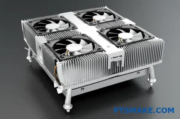
How would you cool a 3kW power inverter in an enclosed cabinet?
Let’s tackle a common challenge. You have a 3kW inverter inside a sealed cabinet. Heat is building up fast. What is the best cooling strategy?
We have three main options. A large internal heat sink with fans. An external heat sink. Or a liquid cooling loop.
Each has its pros and cons. The right choice depends on your specific needs. Let’s compare them.
| Cooling Method | Primary Use Case | Key Factor |
|---|---|---|
| Internal Heat Sink + Fans | Cost-sensitive, moderate heat | Simplicity |
| External Heat Sink | Sealed environments, high reliability | Isolation |
| Liquid Cooling | Extreme performance, tight space | Efficiency |
This guide helps you decide.
Analyzing the Constraints
Choosing the right solution requires looking at your project’s limits. These are usually cost, available space, and required performance. Let’s break down how each option stacks up.
Cost vs. Performance
A large internal heat sink is often the most budget-friendly choice. Paired with high-CFM fans, it handles moderate heat loads effectively. It is a simple, reliable solution we often see.
Liquid cooling is on the other end. It offers the best performance, especially in compact spaces. However, the initial cost and complexity are much higher. It involves pumps, radiators, and tubing.
An external heat sink is a middle ground. It costs more than an internal setup but is less complex than liquid cooling. It excels at moving heat completely outside the cabinet. This is great for sensitive electronics.
Space and Maintenance Considerations
The internal solution needs enough room inside the cabinet for the heat sink and proper airflow. If space is tight, this might not work.
Liquid cooling can be very compact at the component level. But you still need space for the radiator and pump. Maintenance is also more involved, with potential leak points.
The key is balancing the system’s thermal resistance7 against these practical constraints. At PTSMAKE, we use CNC machining to create custom heat sinks. This allows for optimized designs that fit tight spaces perfectly, improving efficiency without the complexity of liquid cooling.
| Constraint | Internal Sink + Fans | External Sink | Liquid Cooling |
|---|---|---|---|
| Initial Cost | Low | Medium | High |
| Performance | Good | Very Good | Excellent |
| Space Needed | High (Internal) | Medium (External) | Low (Component) |
| Maintenance | Low | Low | Medium |
| Complexity | Low | Medium | High |
Choosing the best cooling for a 3kW inverter is not about one "right" answer. It is about evaluating trade-offs. You must balance cost, space, and performance to find the ideal solution for your specific enclosed cabinet application.
How do you troubleshoot an overheating system with a large heat sink?
When a system with a large heat sink overheats, a methodical approach is key. Don’t just assume the heat sink is faulty. Start with the basics.
I always use a diagnostic checklist. This structured process helps isolate the problem quickly and efficiently. It avoids guesswork.
This simple checklist covers the most common culprits.
Diagnostic Checklist
| Check Area | Primary Goal |
|---|---|
| Airflow | Ensure air is moving correctly |
| Obstructions | Remove physical blockages |
| Contact | Verify thermal transfer |
| Environment | Assess external factors |
| Power Load | Confirm heat generation is as expected |
Following these steps in order often reveals the issue without complex disassembly.
A Deeper Diagnostic Dive
A simple checklist is a great start. But let’s break down each step for a more thorough investigation. This ensures nothing is overlooked, especially in complex industrial systems.
Step 1: Verify Airflow and Fan Operation
Are the fans actually spinning? Check their RPM in the system’s monitoring software. Also, feel for air moving away from the large heat sink. A dead fan is an obvious but common issue.
Step 2: Inspect for Dust and Blockages
Dust is a surprisingly effective insulator. Clogged heat sink fins can drastically reduce performance. Check intake filters and exhaust vents for obstructions, not just the heat sink itself.
Step 3: Re-evaluate Thermal Interface and Mounting
A poor TIM application creates air gaps. Uneven mounting pressure does the same. This significantly increases the thermal interface resistance8, hindering heat transfer from the component to the heat sink. At PTSMAKE, we often machine mounting brackets that ensure perfect, even pressure distribution.
Step 4 & 5: Check Ambient and Power Conditions
Is the room hotter than usual? A high ambient temperature gives your cooling system less headroom. Also, verify the component’s power draw. If it’s pulling more power than specified, it will generate more heat than the system was designed for.
| Common Issue | Quick Fix |
|---|---|
| Fan Failure | Replace the fan |
| Dust Buildup | Clean with compressed air |
| Poor TIM | Re-apply TIM and remount |
| High Ambient Temp | Improve room ventilation |
This systematic checklist helps diagnose overheating by examining airflow, physical blockages, thermal contact, and operating conditions. It ensures a comprehensive and logical approach to finding the root cause, even when a large heat sink is involved.
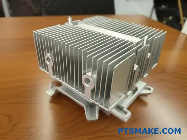
How do you manage the weight and structural integrity of massive heat sinks?
Massive heat sinks present serious mechanical challenges. Their weight can strain mounting points and the entire chassis. Proper management is not just about cooling. It’s about ensuring the product’s long-term reliability.
We must consider the entire mechanical system. This includes the mounting hardware and the structure it attaches to. Material choice is also key.
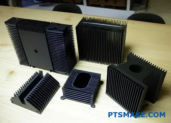
Strategic Material Selection
Choosing the right material is a balance. It’s about weight, thermal performance, and cost. Aluminum is often the best choice for a large heat sink.
| Feature | Aluminum (e.g., 6061) | Copper (e.g., C110) |
|---|---|---|
| Density | Low ( ~2.7 g/cm³) | High ( ~8.96 g/cm³) |
| Thermal Conductivity | Good ( ~167 W/mK) | Excellent ( ~401 W/mK) |
| Cost | Lower | Higher |
Robust Mounting Design
Secure mounting is non-negotiable. We use robust fasteners and distribute the load across multiple points to prevent failure.
When dealing with a very large heat sink, we look beyond its static weight. We must account for dynamic forces. These include shock and vibration during shipping or operation. A heavy component can act like a lever, creating huge stress on mounting points.
This requires a holistic approach to design. The heat sink and chassis must work as one integrated system. It is a common oversight we help our clients at PTSMAKE avoid.
Chassis Reinforcement Strategies
Often, the product’s chassis needs reinforcement. A standard sheet metal enclosure might not be enough. Extra support prevents flexing and fatigue over time. The structural integrity of the entire assembly is at stake.
| Reinforcement Method | Benefit | Common Application |
|---|---|---|
| Stiffening Ribs | Adds strength with minimal material | Sheet metal enclosures |
| Support Brackets | Transfers load to a stronger frame area | Heavy cantilevered components |
| Thicker Materials | Increases overall chassis strength | High-vibration environments |
The goal is to maintain the system’s shape and alignment. Poor support can lead to connection failures or damage to the PCB. In past projects, we’ve found that proper bracing improves the overall [Torsional rigidity]()9 of the device, ensuring its long-term durability. We always analyze the entire mechanical load path to guarantee a reliable solution.
Managing massive heat sinks requires a focus on mechanics. Secure mounting points, chassis reinforcement, and smart material choices like aluminum are crucial. These steps ensure both thermal performance and the structural integrity of the final product, preventing long-term failure.
What are the most common failure modes in large thermal systems?
Large thermal systems have several key points of failure. Understanding these helps in designing more robust and reliable solutions. It is crucial to anticipate these potential issues.
This planning prevents costly downtime and future repairs. Let’s explore the most common failure modes. They often occur in predictable areas of the system.
Key Failure Hotspots
| Failure Mode | Component Affected | Primary Cause |
|---|---|---|
| Airflow Blockage | Heat Sink Fins | Dust & Debris |
| Reduced Conduction | Thermal Interface | Material Degradation |
| Mechanical Stress | Entire Assembly | Vibration & Shock |
| No Airflow | Fans | Bearing/Motor Wear |
Let’s look deeper into these failure modes. Each one presents a unique challenge for system reliability. Proactive design choices can mitigate these risks effectively. At PTSMAKE, we focus on anticipating these issues early.
Fan Malfunction
Fans are active components, making them prone to wear. Bearings can seize or the motor can burn out. This immediately stops forced convection, causing temperatures to rise rapidly. Quality fan selection is non-negotiable for system longevity.
TIM Degradation
Thermal Interface Material (TIM) is critical. It ensures efficient heat transfer between components. Over time, it can dry out, crack, or suffer from [Thermal Interface Material pump-out]()10. This creates insulating air gaps that block heat flow.
Clogged Fins
Dust and debris are silent killers for thermal systems. They accumulate on fins, especially on a large heat sink. This buildup insulates the fins and severely restricts airflow. Performance degrades slowly until the system eventually overheats.
Environmental Impact on Fins
| Environment | Debris Type | Clogging Risk |
|---|---|---|
| Industrial | Oil, Metal Dust | High |
| Office | Fibers, Dust | Medium |
| Clean Room | Minimal Particles | Low |
Mechanical Failure
Vibration and physical shock can cause severe damage. Solder joints can crack and fasteners can loosen over time. This can lead to a complete structural failure of the thermal solution, compromising the entire device.
Understanding these common failures—fan wear, TIM breakdown, clogged fins, and mechanical stress—is the first step. Proactive design, quality components, and planned maintenance are key to ensuring long-term system reliability and avoiding unexpected shutdowns.
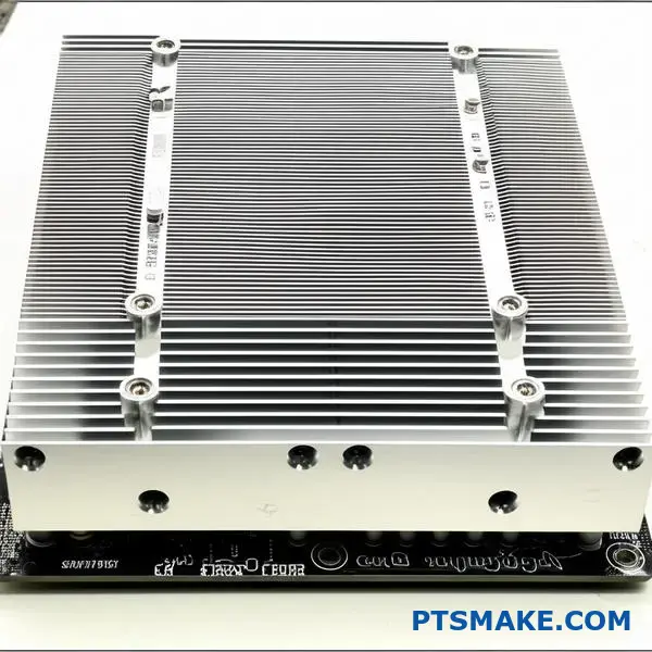
How do you integrate a massive heat sink into a system chassis?
A massive heat sink is only one piece of the puzzle. True thermal performance comes from holistic system design. You must think about the entire chassis.
This means planning the airflow path carefully. Cool air needs a clear path in. Hot air needs a direct path out. They should never mix. This is a common failure point. We also manage fans and pumps.
Key System Design Factors
| Factor | Importance | Common Challenge |
|---|---|---|
| Airflow Path | High | Obstructions, dead zones |
| Intake/Exhaust | High | Air recirculation |
| Fan Integration | Medium | Vibration, noise |
| Power Delivery | Medium | Insufficient power for fans |
This total approach ensures your large heat sink performs at its peak.
Integrating a large heat sink requires thinking beyond the component itself. The chassis becomes an active part of the cooling system. A poorly designed airflow path can render even the best heat sink ineffective.
The goal is to create a wind tunnel inside your enclosure. This prevents issues like [thermal recirculation]()11, where hot exhaust air is pulled back into the cool air intake. This dramatically reduces cooling efficiency.
Strategic Airflow Management
We must design clear, unobstructed paths for air. This involves careful component placement and sometimes custom ducting, which is a service we provide at PTSMAKE.
Pressure Dynamics
Creating the right air pressure inside the chassis is key. You can choose between two main strategies.
| Pressure Type | Description | Pros | Cons |
|---|---|---|---|
| Positive | More intake fans than exhaust | Keeps dust out | Can create hot spots |
| Negative | More exhaust fans than intake | Excellent heat removal | Pulls in dust |
Component Integration
Mechanical and electrical planning is also vital. Fans must be mounted securely to avoid vibration. This often requires custom brackets.
Pumps for liquid cooling need stable power and dedicated mounting points. We plan the wiring routes carefully to avoid interfering with airflow. These details are critical for a reliable system.
A holistic design approach is essential. Effective integration considers the entire system’s airflow, pressure, and the mechanical and electrical setup of all cooling components. This ensures your massive heat sink works as intended.
Unlock Large Heat Sink Solutions With PTSMAKE Expertise
Ready to transform your high-power applications with custom large heat sink manufacturing? Contact PTSMAKE today for a fast, no-obligation quote and see why global leaders trust us for precision, quality, and reliability. Let’s solve your thermal challenges together—submit your inquiry now!

Understanding this metric helps in selecting the most effective and cost-efficient heat sink for your specific application. ↩
Learn how this metric is crucial for evaluating and comparing heat sink performance effectively. ↩
Understand this key metric to see how it directly impacts your device’s cooling efficiency and overall performance. ↩
Learn more about these special non-conductive liquids and their properties for safe electronics cooling. ↩
Learn how this critical metric influences heat sink design for high-performance electronics. ↩
Learn how to optimize thermal interface material performance. ↩
Learn how this critical value determines the cooling efficiency of your thermal management system. ↩
Understand this key metric that impacts your large heat sink’s real-world cooling performance. ↩
Understand how this property prevents twisting and ensures your assembly remains stable under load. ↩
Learn the physics behind this effect and discover effective strategies for its prevention in your designs. ↩
Understand how this common airflow problem can sabotage your cooling efficiency and how to avoid it. ↩