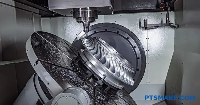
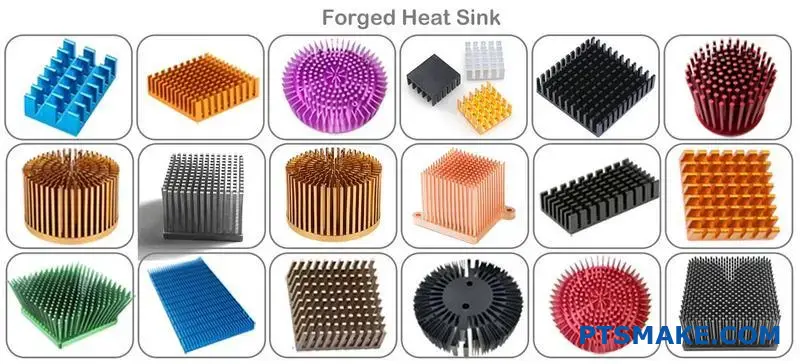
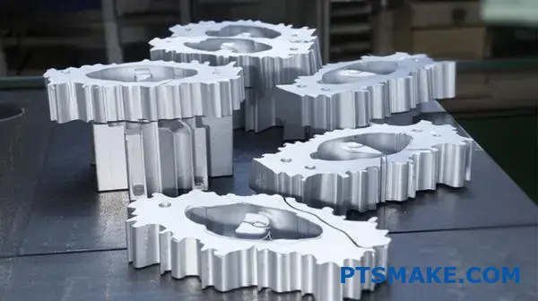
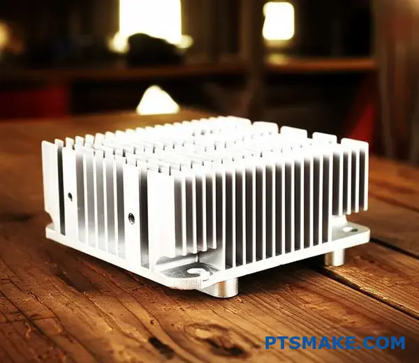
Finding the right heat sink manufacturing method can make or break your thermal management system. Many engineers struggle with extruded or machined heat sinks that hit performance walls, especially when dealing with high-power applications where every degree matters.
Forged heat sinks offer superior thermal performance through enhanced material density, optimized grain structure, and one-piece construction that eliminates thermal interfaces. The forging process creates stronger heat conduction pathways and allows complex geometries impossible with traditional manufacturing methods.
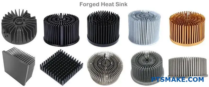
I’ve worked with many clients who switched from standard heat sinks to forged solutions and saw immediate improvements in thermal performance. The key lies in understanding how forging affects material properties at the microscopic level and leveraging the design freedom this process provides for your specific application.
How does forging impact material thermal conductivity at a micro-level?
Forging does more than just shape metal. It transforms its internal structure. This change directly improves how well it transfers heat.
At a micro-level, it’s about grain flow and density. Forging aligns the material’s grains and eliminates tiny voids. This creates a superior path for heat to escape.
| Feature | Forged Material | Cast Material |
|---|---|---|
| Grain Structure | Aligned & Refined | Random & Coarse |
| Density | High | Lower (Porosity) |
| Voids | Nearly Eliminated | Present |
This refinement is key to thermal performance.
The Microscopic Advantage: Grain Flow and Density
Forging applies immense pressure to a workpiece. This pressure forces the metal’s grain structure to deform and elongate. The grains align with the direction of the metal flow.
This creates a continuous, unbroken path. Heat can travel easily along these aligned grains. It’s like a highway for thermal energy, free of traffic jams.
This directional alignment gives the material unique anisotropic properties1. Thermal conductivity becomes significantly higher along the grain flow.
Furthermore, the forging process squeezes out microscopic voids. These tiny pockets, often present in cast materials, trap air and act as insulators. By eliminating them, forging creates a denser, more thermally conductive part. This is why a forged heat sink often outperforms its cast or machined counterparts.
Forging vs. Other Methods
When you machine a part from a solid billet, you cut right through the material’s natural grain structure. This severs the continuous thermal paths. Casting, on the other hand, results in a random, non-directional grain structure with potential porosity.
| Manufacturing Method | Grain Flow | Micro-Voids | Thermal Path |
|---|---|---|---|
| Forging | Aligned | Minimized | Uninterrupted |
| Casting | Random | Common | Interrupted |
| Machining (Billet) | Cut | Minimal | Severed |
In our projects at PTSMAKE, we’ve seen forged components consistently offer better thermal management.
Forging enhances thermal conductivity by refining grain structure and eliminating microscopic voids. This creates a denser material with superior, directional heat transfer paths compared to casting or machining from billet.
What defines the performance limits of a forged heat sink?
Every design has its limits. A forged heat sink is no different. Its performance isn’t infinite. It’s bound by fundamental laws of physics and material science.
Let’s explore these theoretical constraints. Understanding them helps us engineer better thermal solutions.
Material’s Natural Ceiling
The material itself sets the first limit. Its ability to conduct heat is a hard cap on performance. You can’t move heat faster than the material allows.
| Material | Thermal Conductivity (W/mK) |
|---|---|
| Copper C110 | ~385 |
| Aluminum 6061 | ~167 |
| Aluminum 6063 | ~201 |
The Role of Airflow
Next is convection. This is how the heat sink transfers heat to the air. Without sufficient airflow, heat gets stuck on the fins.
The theoretical limits are where practical engineering begins. At PTSMAKE, we don’t just accept them; we work within these constraints to create optimal designs for our clients.
Beyond Pure Materials
While pure copper offers great conductivity, its cost and weight can be prohibitive. Aluminum alloys like 6061 or 6063 present a balanced solution. They offer good performance and are ideal for the forging process. Each material choice affects the forged heat sink’s final efficiency.
Harnessing Convection
Effective convection is crucial. The design of the fins—their shape, spacing, and orientation—must be optimized for the system’s airflow. A great design works with the airflow, not against it.
Air moving across a fin forms a thin, slow-moving Boundary layer2. This layer can insulate the very surface you’re trying to cool. Our designs aim to disrupt this.
Forging’s Geometric Constraints
Forging creates strong, dense fins. But there are limits. The process defines the minimum fin thickness and the maximum height-to-thickness ratio.
| Fin Spacing | Airflow Resistance | Surface Area |
|---|---|---|
| Wide | Low | Lower |
| Narrow | High | Higher |
This table shows a key trade-off. Tighter fins increase surface area but can also restrict airflow if not designed carefully. This is the surface area-to-volume ratio limit inherent in forging.
A forged heat sink’s performance is ultimately governed by three factors: the material’s thermal conductivity, the physics of convection, and the geometric limitations of the forging process itself. These principles form the foundation of effective thermal design.
Why is a one-piece construction a key advantage of forging?
The single-piece design of a forged heat sink is its biggest thermal advantage. It completely removes the need for joints. Think of heat flowing like water in a pipe.
Any joint, seam, or gap is like a blockage. It slows down the flow.
The Problem with Joints
In multi-piece heat sinks, the base and fins are separate parts. They are joined together later. This creates a tiny gap, an interface that heat must cross. This interface is the weak link.
A one-piece forged heat sink has no such weak link.
One-Piece vs. Multi-Piece
| Feature | Forged One-Piece | Multi-Piece Assembly |
|---|---|---|
| Joints | None | Multiple |
| Heat Path | Uninterrupted | Interrupted |
| Failure Points | Fewer | More |
| Performance | Higher | Lower |
The Impact of Thermal Resistance
Every material resists heat flow to some degree. But the biggest enemy of thermal performance is the gap between two surfaces. This is called thermal interface resistance.
Even perfectly smooth surfaces have microscopic imperfections. These create air gaps when pressed together. Air is a terrible conductor of heat. So, heat transfer across this joint is very inefficient.
Bridging the Gap
Manufacturers use special materials to fill these gaps. These are called thermal interface material3. They can be pastes, pads, or adhesives. While they are better than air, they are not perfect. They still add their own layer of thermal resistance.
A forged heat sink avoids this entire problem. Since the base and fins are a single, continuous piece of metal, there are no gaps to fill. The heat path is seamless.
Comparing Heat Transfer Paths
| Heat Sink Type | Key Thermal Barrier | Heat Transfer Efficiency |
|---|---|---|
| Forged (One-Piece) | Material conductivity only | Very High |
| Bonded Fin | Thermal adhesive layer | Moderate |
| Stacked Fin | Interface between fins | Moderate to Low |
| Extruded | Base-to-fin junction | High (but limited geometry) |
In our experience at PTSMAKE, eliminating interface resistance is crucial for high-power applications. A forged component ensures heat moves from the source to the fins without any interruptions. This leads to a cooler device and better reliability.
A one-piece forged part eliminates thermal interface resistance. This creates an unbroken path for heat to escape, resulting in superior cooling performance compared to multi-piece assemblies that rely on imperfect thermal joints.
What are the primary heat transfer modes in a forged heat sink?
A forged heat sink manages heat through three primary modes. Each plays a distinct role in cooling your electronics. It’s a team effort.
Understanding this process is key to designing effective thermal solutions. Let’s break down how it all works together.
Conduction: The First Step
Heat first moves from the source into the heat sink’s base. This is conduction. The material itself carries the thermal energy away.
Convection: Moving Heat to Air
Next, the heat travels up the fins. Air flowing over these fins carries the heat away. This process is called convection.
Radiation: A Helping Hand
Finally, heat radiates from all surfaces of the heat sink. This is like the heat you feel from a warm object without touching it.
| Transfer Mode | Role in a Forged Heat Sink |
|---|---|
| Conduction | Moves heat from the component into the heat sink. |
| Convection | Transfers heat from the fins to the surrounding air. |
| Radiation | Emits heat from all surfaces as thermal energy. |
Heat transfer in a forged heat sink is a fascinating dance between physics and material science. It’s not just about having fins. The efficiency of the entire system depends on how well these three modes work together. The forging process itself provides a significant advantage.
How Forging Optimizes Conduction
Forging creates a superior pathway for heat. It does this by shaping the metal under extreme pressure. This process aligns the material’s internal grain structure.
An uninterrupted grain flow means fewer obstacles for heat. This directly improves the material’s thermal conductivity4, a key performance metric. Think of it like a smooth highway versus a road with potholes. Heat travels much faster.
Comparing Forging to Other Methods
At PTSMAKE, we’ve seen the difference firsthand. Forging eliminates the microscopic voids and imperfections often found in casting. It also avoids the linear grain structure of extrusion, allowing for more complex and efficient fin designs.
This superior internal structure is why a forged heat sink often outperforms others.
| Manufacturing Method | Conduction Pathway | Typical Performance |
|---|---|---|
| Forging | Uninterrupted grain flow | Excellent |
| Extrusion | Linear grain flow | Good |
| Casting | Porous, random structure | Fair |
A forged heat sink efficiently uses conduction, convection, and radiation. The forging process is crucial. It creates an ideal grain structure, maximizing conduction from the heat source to the fins for superior cooling performance.
What is the role of the base in a forged heat sink?
The base of a forged heat sink is its foundation. It performs two critical jobs. First, it spreads heat. It takes concentrated heat from a small source, like a CPU.
Then, it distributes this heat evenly across a larger area. This allows the fins to dissipate heat more effectively.
Its second job is to provide a solid, flat mounting surface. This ensures optimal contact with the heat-generating component. The thickness of this base is a key design parameter that dictates performance.
| Primary Function | Key Benefit |
|---|---|
| Heat Spreading | Prevents hotspots and improves fin efficiency. |
| Mounting Interface | Ensures maximum thermal transfer from the source. |
Beyond a Simple Foundation
The base is the unsung hero of thermal management. Without effective spreading, heat gets bottlenecked at the source. The fins, no matter how well-designed, can’t do their job.
This bottleneck effect is a core challenge in thermal design. A thicker base generally lowers the thermal spreading resistance5. It gives heat more room to travel laterally before moving up into the fins.
However, this creates a trade-off. A thicker base means more material, more weight, and higher cost. In our projects at PTSMAKE, we constantly balance these factors to meet client specifications.
The Critical Need for Flatness
The base must also be perfectly flat. Any air gaps between the heat source and the sink base act as insulators. This severely hinders thermal transfer.
This is where precision manufacturing is vital. Our CNC machining services ensure the base meets extremely tight flatness tolerances. This guarantees the best possible thermal contact.
Base Thickness as a Design Choice
Choosing the right base thickness is a critical step for any forged heat sink.
| Base Thickness | Advantage | Disadvantage |
|---|---|---|
| Thin | Lighter, lower material cost. | Poor heat spreading. |
| Thick | Excellent heat spreading. | Heavier, higher material cost. |
Finding the optimal thickness requires careful analysis. It’s about achieving performance goals without adding unnecessary weight or cost to the final product.
The base is a critical component that spreads heat and provides a mounting interface. Its thickness is a crucial design trade-off, balancing thermal performance with the physical constraints of weight and cost.
How are forging defects defined and what is their thermal impact?
Forging defects are more than just cosmetic flaws. They are structural imperfections that directly harm performance. This is especially true for a forged heat sink.
Common issues like laps, cracks, or incomplete fills create serious problems. They break the intended grain structure of the metal.
This disruption introduces thermal barriers. These barriers compromise the heat sink’s primary job: dissipating heat effectively.
Common Forging Defects
| Defect Type | Description |
|---|---|
| Laps | A folding of metal onto its own surface. |
| Cracks | Fissures caused by stress during forging or cooling. |
| Incomplete Fills | The die cavity is not completely filled with material. |
The Hidden Impact on Thermal Performance
A perfect forging provides an uninterrupted path for heat. The continuous grain structure acts like a highway for thermal energy to escape. Defects destroy this highway.
When a lap or crack forms, it creates a microscopic air gap. Air is an excellent insulator, not a conductor. This tiny pocket of trapped air becomes a significant barrier to heat transfer, right where you need it least.
This dramatically increases the part’s thermal impedance6. The heat struggles to cross this barrier, causing localized hot spots and reducing the overall efficiency of the forged heat sink.
In our work at PTSMAKE, we’ve seen how even a small, invisible crack can render a heat sink ineffective. The heat essentially hits a wall and cannot dissipate as designed.
Heat Flow Comparison
| Part Condition | Grain Structure | Heat Path | Performance |
|---|---|---|---|
| Defect-Free | Continuous & Aligned | Uninterrupted | Optimal |
| With Defects | Disrupted & Broken | Obstructed by Gaps | Compromised |
This is why meticulous process control is non-negotiable. It’s not about making parts look good; it’s about ensuring they perform flawlessly under thermal load. Every defect introduces a point of failure.
Forging defects like laps and cracks are not superficial. They disrupt the metal’s grain structure and create internal thermal barriers. This directly compromises a heat sink’s ability to dissipate heat, leading to poor performance and potential device failure.
What are the main types of forging processes for heat sinks?
Choosing the right forging process is critical. It directly impacts your heat sink’s thermal performance, cost, and final appearance. The choice hinges on temperature.
We primarily categorize forging into three types: cold, warm, and hot. Each method offers a unique set of trade-offs. Understanding these differences is key to success.
Comparing the Core Forging Methods
Below is a quick overview. It shows how temperature changes the game for precision and material strength in a forged heat sink.
| Feature | Cold Forging | Warm Forging | Hot Forging |
|---|---|---|---|
| Temperature | Room Temperature | Intermediate | High Temperature |
| Precision | Highest | High | Moderate |
| Surface Finish | Excellent | Good | Fair |
| Cost | Low (for high vol.) | Moderate | High (due to energy) |
A Deeper Look at Each Process
The fundamental difference between these methods is the workpiece temperature relative to the material’s recrystallization temperature7. This single factor changes everything from the final part’s strength to its geometric complexity.
Cold Forging
This process is done at room temperature. It requires significant force but produces parts with excellent dimensional accuracy and surface finish. Secondary machining is often unnecessary.
The material is strengthened through work hardening. This makes cold-forged heat sinks very durable. However, this process is best for simpler shapes and high-volume production runs where tooling costs can be justified.
Hot Forging
Performed at very high temperatures, hot forging makes the metal more ductile. This allows for the creation of highly complex geometries that are impossible with cold forging. It requires less force to shape the material.
The trade-off is lower dimensional precision and a rougher surface finish due to scaling. It often requires post-machining to meet tight tolerances.
Warm Forging
Warm forging strikes a balance between the two extremes. It offers better precision and surface finish than hot forging. It also allows for more intricate shapes than cold forging. At PTSMAKE, we often find this is a versatile sweet spot for many projects.
| Process | Key Advantages | Typical Applications |
|---|---|---|
| Cold Forging | High precision, excellent finish, high strength | High-density pin fin heat sinks, small components |
| Warm Forging | Good balance of precision and complexity | Automotive parts, moderately complex heat sinks |
| Hot Forging | Complex shapes, low forming forces | Large structural parts, complex industrial heat sinks |
The choice is a balance. Cold forging delivers precision, while hot forging enables complexity. Warm forging offers a versatile middle ground. Selecting the right path depends on your specific design requirements, material choice, and production volume.
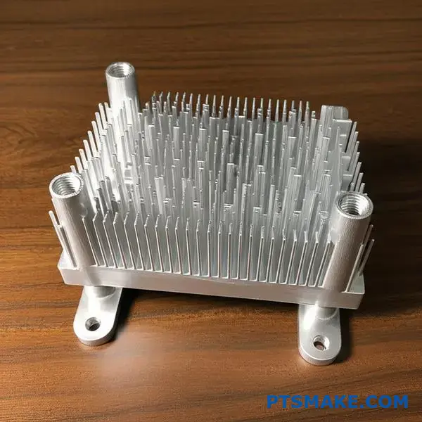
How are forged heat sinks classified by fin geometry?
When selecting a forged heat sink, fin geometry is a critical decision. The shape of the fins directly impacts how effectively heat is dissipated.
Common Fin Geometries
We primarily see three types in our projects: pin, elliptical, and straight fins. Each has a unique profile.
Their design influences both thermal performance and air resistance. Choosing the right one is key for optimal cooling in any application.
Quick Comparison
| Fin Type | Best For | Key Feature |
|---|---|---|
| Straight | Forced Airflow | Low Pressure Drop |
| Pin | Natural Convection | Omni-directional Airflow |
| Elliptical | High-Velocity Air | Aerodynamic Efficiency |
This choice depends entirely on your system’s airflow.
Let’s explore these geometries in more detail. The choice isn’t arbitrary; it’s a careful engineering decision based on airflow dynamics.
Straight Fin Arrays
Straight fins are the most common design. They offer a clear, uninterrupted path for air. This is ideal for forced convection with a fan, as it minimizes air pressure drop.
However, their performance suffers if the airflow isn’t aligned with the fins. It’s a highly directional solution.
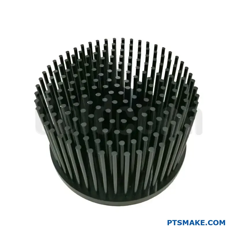
Pin Fin Arrays
Pin fins excel in environments with low or unpredictable airflow. Their 360-degree exposure allows them to capture air from any direction, making them perfect for natural convection.
This design increases air turbulence, which boosts heat transfer. The goal is to minimize the overall thermal resistance8 from the heat source to the ambient air.
Elliptical Fin Arrays
Elliptical fins are a more advanced, aerodynamic shape. They combine the directional strength of straight fins with a lower resistance to high-velocity airflow.
In past projects at PTSMAKE, we have seen that they can outperform straight fins in tightly packed systems where maintaining airflow is critical.
| Geometry | Aerodynamic Advantage | Thermal Advantage | Typical Use |
|---|---|---|---|
| Straight | Low pressure drop in linear flow | Efficient in forced convection | Server CPUs, Power Supplies |
| Pin | Omni-directional flow acceptance | High turbulence for natural convection | LED lighting, Outdoor electronics |
| Elliptical | Very low drag at high speeds | Maintains airflow in dense arrays | High-performance computing, Telecom |
Choosing the right forged heat sink fin geometry is a balance. Straight fins suit forced air, pin fins excel in natural convection, and elliptical fins offer an aerodynamic edge. Matching the design to your specific airflow conditions is essential for optimal performance.
How do forged heat sinks compare to extruded or skived alternatives?
Choosing the right heat sink is critical. It impacts performance, cost, and design. Forged, extruded, and skived fins each have unique benefits.
To help you decide, let’s compare them directly. This comparison focuses on the key factors you need to consider.
Quick Comparison Overview
Here is a simple table to start. It gives you a high-level view of each technology’s strengths and weaknesses.
| Feature | Forged | Extruded | Skived |
|---|---|---|---|
| Thermal Performance | Excellent | Good | Very Good |
| Design Freedom | Good | Limited | Excellent |
| Unit Cost (High Vol.) | Low | Very Low | High |
This gives a quick snapshot for initial evaluation.
Detailed Evaluation Matrix
Let’s break down the details further. Making the optimal choice requires a deeper understanding of each manufacturing method’s nuances. At PTSMAKE, we help clients navigate these trade-offs daily.
Thermal Performance Insights
A forged heat sink offers excellent, omnidirectional heat dissipation. This is due to its uniform grain structure.
Extruded heat sinks perform well, but their thermal properties can be anisotropic9. Heat moves better along the extrusion length than across it. Skived fins are one piece, ensuring a perfect thermal path from base to fin tip.
Design and Mechanical Considerations
Design freedom is a major factor. Forging allows for complex 3D shapes like round or elliptical pins. Extrusion limits you to 2D profiles with a fixed cross-section.
Skiving offers the highest aspect ratios for very tall, thin fins. This is ideal for forced convection cooling.
Here is a more structured comparison matrix we use.
| Criterion | Forged Heat Sink | Extruded Heat Sink | Skived Heat Sink |
|---|---|---|---|
| Thermal Performance | Isotropic, Excellent | Anisotropic, Good | Excellent, seamless fin-to-base |
| Design Freedom (Aspect Ratio) | Good (up to 25:1) | Limited (up to 12:1) | Excellent (up to 50:1) |
| Mechanical Integrity | Very High, Robust | High | Moderate, fins can be delicate |
| Manufacturing Cost | Medium (Low in high vol.) | Low (Very low in high vol.) | High |
| Tooling Investment | High | Low-to-Medium | Low |
This detailed breakdown helps pinpoint the best solution for specific application needs. The initial tooling for a forged heat sink can be higher, but unit costs drop significantly with volume.
This matrix provides a practical guide for choosing between forged, extruded, and skived heat sinks. The best option depends on your specific thermal needs, design constraints, and production volume. Forging often hits a sweet spot for performance and scalability in many applications.
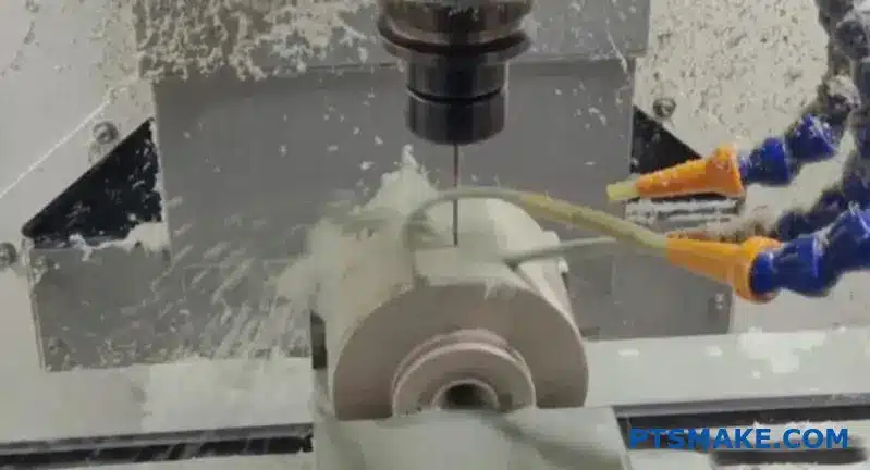
What are the typical post-forging secondary operations and why?
A raw forging is strong, but it’s rarely ready for use. It is simply the starting point. Post-forging operations turn this raw part into a finished component.
These steps add precision and specific properties. Let’s look at a typical workflow for a component like a Forged heat sink.
Typical Post-Forging Workflow
| Step | Operation | Purpose |
|---|---|---|
| 1 | Deburring | Safety & Preparation |
| 2 | CNC Machining | Precision & Features |
| 3 | Anodizing | Protection & Performance |
This sequence ensures each step builds upon the last. It helps achieve optimal results for the final product.
A forged part needs refinement to meet exact specifications. This process is not just about cleaning up the part. It is about adding critical value at each stage. Every operation has a clear and distinct purpose.
Step 1: Deburring for a Clean Start
Before any precision work, we must deburr the part. This process removes the sharp edges, or burrs. These are left over from the forging process itself.
This is a crucial first step for two reasons. It ensures the part is safe to handle. It also prepares it for accurate mounting in CNC machines. A clean surface is key for precision.
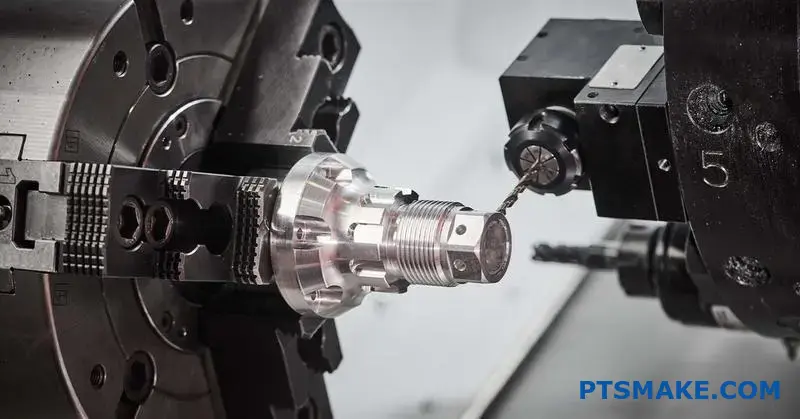
Step 2: CNC Machining for Precision
Forging provides the basic shape and material strength. However, it cannot achieve tight tolerances for features like mounting surfaces or holes. This is where CNC machining is essential.
At PTSMAKE, we use CNC milling to create perfectly flat surfaces. This is vital for a Forged heat sink to make solid contact with a heat source. We also drill and tap holes to exact specifications.
Key Machining Goals
| Feature | Machining Goal | Why It Matters |
|---|---|---|
| Mounting Face | Achieve high flatness | Ensures maximum thermal transfer |
| Mounting Holes | Precise location & size | Guarantees proper assembly |
| Fins/Channels | Final shaping | Optimizes airflow and cooling |
Step 3: Anodizing for Durability and Performance
The final step is often a surface treatment. Anodizing is a popular choice for aluminum forgings. It is an Electrolytic passivation10 process that creates a hard, durable oxide layer on the surface.
This layer provides excellent corrosion resistance. For a heat sink, it also increases the surface emissivity. This helps radiate heat more effectively, improving cooling performance significantly.
Post-forging operations are essential for transforming a rough part. Steps like machining and anodizing add the necessary precision, features, and surface properties. They ensure the final component performs reliably and meets all design requirements.
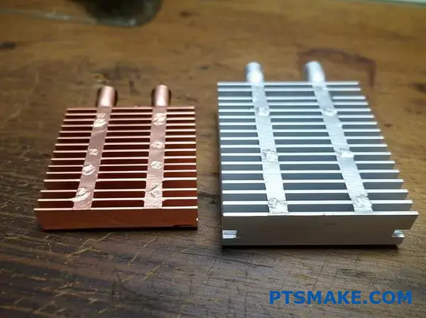
How are forged copper and aluminum heat sinks structurally different?
Choosing between forged copper and aluminum involves more than thermal performance. It’s a critical decision that impacts weight, cost, and manufacturability. Each material behaves differently during the forging process.
This directly influences the final heat sink structure and its suitability for your specific application.
Key Material Properties
Copper is the undisputed champion of thermal conductivity. However, aluminum is much lighter and generally more cost-effective. These core differences are the starting point for any design consideration.
| Property | Forged Copper | Forged Aluminum |
|---|---|---|
| Thermal Conductivity | Excellent (~400 W/mK) | Good (~220 W/mK) |
| Density | High (8.96 g/cm³) | Low (2.70 g/cm³) |
| Relative Cost | Higher | Lower |
Ultimately, the choice depends on balancing these factors. You must decide if copper’s thermal advantage justifies its extra weight and cost.
A Deeper Comparison
The structural differences extend well into the manufacturing process. Forging copper is significantly more difficult than forging aluminum. It requires much higher pressures and temperatures. This complexity often translates to higher tooling costs and potentially longer lead times.
Forging Difficulty and Design
The malleability of aluminum allows for more intricate fin designs during forging. Copper’s resistance to deformation can sometimes limit the complexity of a forged heat sink. This is a crucial point we often discuss with clients at PTSMAKE.
Furthermore, aluminum’s low density makes it the clear winner for weight-sensitive applications. A copper heat sink will be over three times heavier than an identically sized aluminum one.
Corrosion and Material Compatibility
Copper naturally resists corrosion well. However, a major structural concern arises when it’s in direct contact with aluminum in a moist environment. This can lead to Galvanic corrosion11, which can degrade the materials over time. Proper plating or thermal interface materials are essential to prevent this.
When to Choose Copper Over Aluminum
Certain applications demand the superior thermal dissipation that only copper can provide. The decision is usually driven by extreme heat loads in compact spaces.
| Application | Recommended Material | Primary Reason |
|---|---|---|
| High-Performance CPUs/GPUs | Copper | Maximum heat dissipation in a small footprint. |
| High-Power Lasers | Copper | Rapidly pulls heat away from sensitive diodes. |
| Industrial Power Modules | Copper | Manages intense, constant thermal loads reliably. |
| Automotive LED Headlights | Aluminum | Good performance with low weight and cost. |
The choice hinges on whether your device’s performance and longevity depend on shedding heat as quickly as possible. If so, copper is the investment.
Choosing between forged copper and aluminum is a balancing act. It requires weighing copper’s superior thermal performance against aluminum’s advantages in weight, cost, and ease of manufacturing. The optimal material is always dictated by the unique demands of your application.
How do you redesign an extruded heat sink into a forged one?
Let’s walk through a practical conversion. This process transforms a simple extruded part into a superior forged heat sink. It’s about smart design choices.
We focus on leveraging forging’s unique strengths. This means creating complex 3D fin shapes and integrating features directly.
Project Conversion Goals
The main goal is to boost thermal performance. We also aim to simplify the final product assembly.
| Design Aspect | Extruded (Before) | Forged (After) |
|---|---|---|
| Fin Geometry | Simple, 2D straight fins | Complex, 3D pin fins |
| Mounting | Separate fasteners needed | Integrated mounting posts |
| Base Design | Uniform thickness | Optimized for heat spreading |
| Airflow | Limited to one direction | Omni-directional |
The main hurdle is the initial tooling investment. A forging die costs more than an extrusion die. So, how do we justify this? We must prove the performance gains outweigh the cost.
At PTSMAKE, we help clients analyze this trade-off. It’s about long-term value, not just initial price.
Optimizing the Design for Forging
Creating complex 3D pin fins is a major advantage. This dramatically increases the surface area. More surface area means better heat dissipation. It’s a key benefit of a forged heat sink.
We also redesign the base. A thicker base directly under the heat source improves heat spreading. This works because forging enhances the material’s isotropic thermal conductivity12. Heat moves efficiently in all directions, not just along one axis.
Integrating Features to Cut Costs
We can forge features like mounting posts directly into the part. This eliminates the need for separate hardware. It also cuts down on assembly time and labor costs. These downstream savings are crucial for justifying the initial tooling investment.
Redesigning for forging uses 3D fins and integrated features to boost performance. While tooling costs are higher, the thermal gains and assembly savings often provide a strong return on investment, making it a smart choice for high-performance applications.
Unlock Advanced Forged Heat Sink Solutions with PTSMAKE
Ready to experience the superior performance, precision, and reliability of custom forged heat sinks? Contact PTSMAKE today for a tailored quote—empower your next project with trusted expertise, fast turnaround, and world-class engineering support. Take action and request your personalized solution now!

Learn how material properties, like thermal conductivity, can differ based on direction. ↩
Learn more about this key concept and its direct impact on heat transfer efficiency. ↩
Explore how different thermal interface materials work and their effects on performance. ↩
Click to understand how this property is crucial for heat sink performance. ↩
Understand this key concept to improve your heat sink’s thermal performance and overall efficiency. ↩
Learn more about how material interfaces and imperfections impede the flow of heat. ↩
Learn how this metallurgical point impacts material strength and formability in forging. ↩
Understand how this critical metric influences your heat sink’s cooling efficiency and design choices. ↩
Understand how material properties differ based on direction and impact thermal performance. ↩
Discover the science behind how this process enhances surface protection and thermal performance. ↩
Learn how this electrochemical process can impact the structural integrity of assemblies with dissimilar metals. ↩
Understand how material properties affect heat transfer for better design choices. ↩