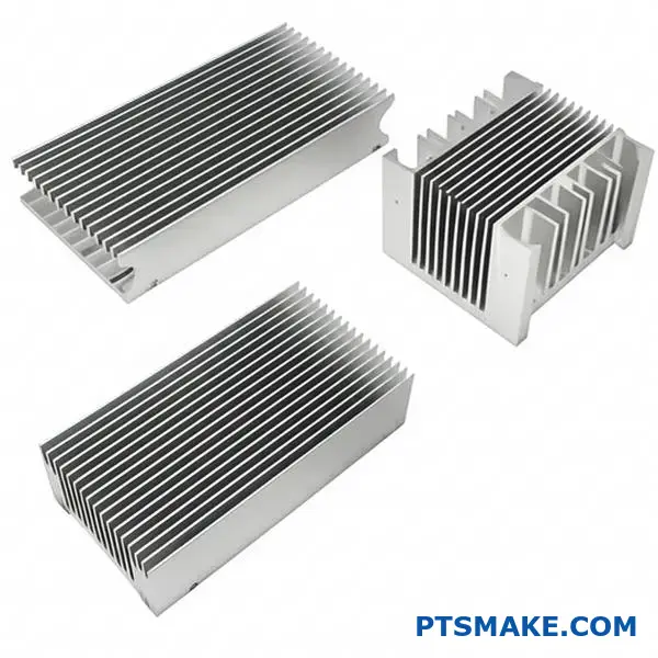
Struggling to design an effective extruded heat sink for your high-power electronics? Many engineers face thermal management challenges when custom cooling solutions require precise specifications, optimal material selection, and manufacturing expertise that standard off-the-shelf heat sinks simply cannot provide.
Custom extruded heat sink design requires understanding aluminum alloy properties, extrusion limitations, fin efficiency principles, and proper manufacturing specifications to create cost-effective thermal management solutions for electronics cooling applications.
I’ve worked with hundreds of thermal management projects at PTSMAKE, and I’ll walk you through the complete process from material selection to final specifications. This guide covers the engineering fundamentals you need to design manufacturable extruded heat sinks that actually perform.
Why is extrusion the default process for aluminum heat sinks?
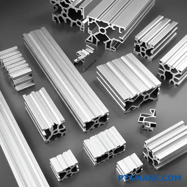
When we talk about aluminum heat sinks, extrusion is almost always the first process that comes to mind. It’s the default choice for a simple reason: It perfectly balances cost, performance, and design flexibility for most applications.
The Material and Process Harmony
Aluminum alloys like 6061 and 6063 are highly malleable. This property makes them ideal for extrusion. We can push the material through a die to create complex fin profiles. This process is both fast and efficient.
A Quick Comparison
| Process | Key Advantage | Best For |
|---|---|---|
| Extrusion | Cost-Effective | Linear, high-volume parts |
| Casting | Complex 3D Shapes | Low-stress applications |
| CNC Machining | High Precision | Prototypes, custom shapes |
A Deeper Look at Manufacturing Choices
While extrusion is dominant, it’s crucial to understand why other methods aren’t the go-to. Each process has trade-offs that impact the final extruded heat sink’s performance and cost.
Limitations of Casting
Casting can create intricate, three-dimensional shapes. However, the resulting material often has microscopic voids or porosity. This reduces its thermal conductivity compared to solid, extruded aluminum. The surface finish is also rougher, which can hinder thermal transfer without secondary processing.
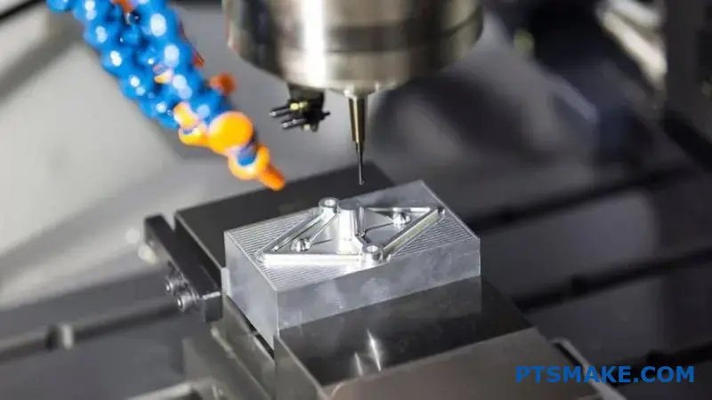
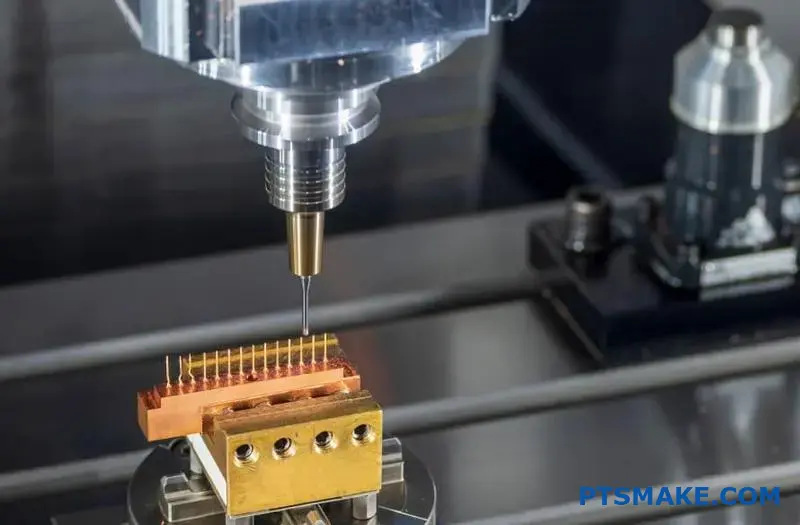
The Cost of CNC Machining
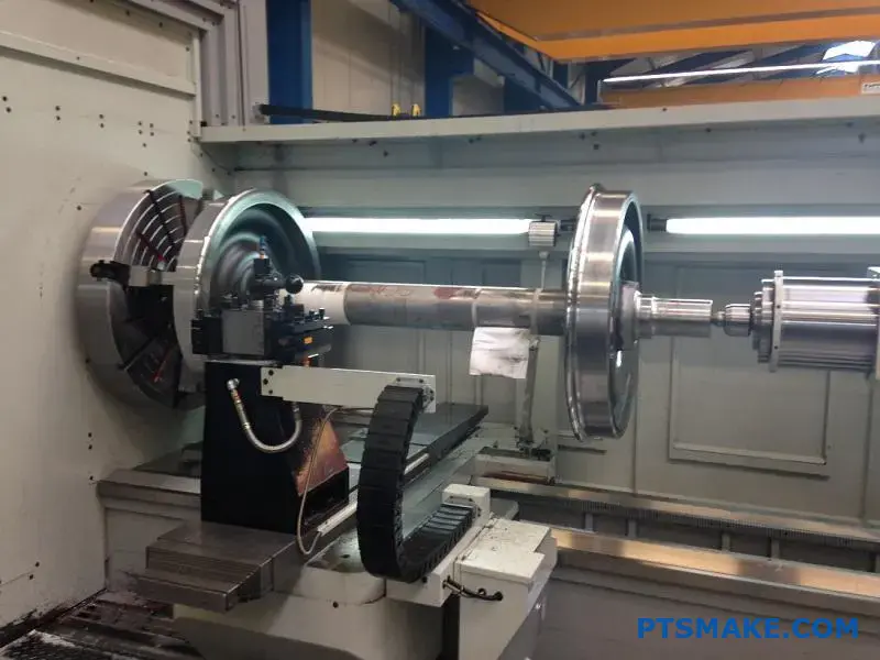
CNC machining offers incredible precision. At PTSMAKE, we use it for prototypes and highly complex geometries. But for simple, linear heat sink profiles, it’s subtractive. This means it cuts away material, which creates significant waste and takes much longer. The cost per unit becomes prohibitive for high-volume production. The properties of the material can also be slightly anisotropic1 after extrusion, a factor we always consider.
The Extrusion Sweet Spot
Extrusion hits the sweet spot. It produces long, continuous profiles with excellent surface finish and material integrity. We then just need to cut them to the required length. This efficiency is unmatched for standard heat sink designs.
| Feature | Extrusion | Casting | CNC Machining |
|---|---|---|---|
| Tooling Cost | Moderate | High | Low (No tooling) |
| Piece Price | Low | Low-Moderate | High |
| Material Waste | Low | Low | High |
| Thermal Conductivity | Excellent | Good | Excellent |
| Design Complexity | Linear 2D | High 3D | Very High 3D |
Extrusion is the default for aluminum heat sinks because it provides the best balance of cost, thermal performance, and manufacturing speed for linear designs. While casting and CNC machining have their specific uses, they can’t match extrusion’s overall efficiency for most applications.
Which aluminum alloys are primarily used for extrusion and why?
When discussing aluminum extrusion, two alloys stand out: 6063 and 6061. They are the industry’s go-to materials for a reason.
Each alloy presents a distinct balance of properties. Understanding these differences is crucial for any project. It helps in selecting the right material for performance and budget.
Key Alloy Comparison
| Property | 6063 Aluminum | 6061 Aluminum |
|---|---|---|
| Primary Feature | Excellent Extrudability | High Strength |
| Surface Finish | Very Good | Good |
| Strength | Medium | Medium to High |
| Common Use | Architectural, Heat Sinks | Structural Components |
A Deeper Dive into Alloy Selection
Choosing the right alloy is more than just looking at a spec sheet. It’s about understanding the practical trade-offs for your specific application.
The Case for 6063 Aluminum
6063 is often called "architectural aluminum." It provides an exceptionally smooth surface finish right after extrusion. This makes it perfect for parts where appearance matters.
Its greatest advantage is superior extrudability. This allows us to create very complex cross-sections. This is vital for parts like custom extruded heat sink profiles with intricate fins. More fins mean more surface area and better cooling.
When Strength is Paramount: 6061 Aluminum
If your component needs to endure significant mechanical stress, 6061 is the clear winner. It contains more magnesium and silicon, which gives it higher strength.
This added durability, however, comes at a cost. It is more difficult to extrude, limiting the complexity of shapes we can achieve. The alloy’s final properties also depend heavily on its heat treatment process. This is something we carefully control at PTSMAKE for every project. The final state of the metal depends on its temper designation2, like T6, which offers maximum strength.
Detailed Property Trade-offs
| Factor | 6063 Aluminum | 6061 Aluminum |
|---|---|---|
| Extrudability | Excellent | Good |
| Thermal Conductivity | ~218 W/m·K | ~180 W/m·K |
| Tensile Strength (T6) | ~241 MPa | ~310 MPa |
| Typical Cost | Lower | Slightly Higher |
| Best For | Complex profiles, good finish | Structural parts, high stress |
The choice between 6063 and 6061 is a classic engineering trade-off. 6063 offers excellent extrudability and finish, ideal for complex extruded heat sinks. 6061 provides superior strength for structural needs, but with some design and cost constraints.
What are the fundamental limits of the extrusion process itself?
Every manufacturing process has its rules. Extrusion is no exception. These aren’t arbitrary guidelines; they are fundamental physical limits. They are dictated by material flow, pressure, and tool strength.
Understanding these constraints is key. It helps in designing a practical and efficient extruded heat sink. It avoids designs that are impossible to produce.
Key Geometric Constraints
The most critical limits relate to the fin geometry. This includes how thin a fin can be and how tall it can grow.
| Parameter | Typical Limit | Impact on Design |
|---|---|---|
| Minimum Fin Thickness | ~0.8 mm to 1.3 mm | Thinner fins are harder to extrude without defects. |
| Maximum Fin Height | Governed by aspect ratio | Taller fins can warp or break during extrusion. |
These numbers are a starting point. They can change based on the specific alloy and press used.
The core challenge lies in pushing aluminum through a steel die. The forces involved are immense. We have to consider how the metal behaves under such extreme pressure.
The Physics Behind the Limits
Imagine forcing a semi-solid material through a complex shape. If a fin channel in the die is too thin, the aluminum might not flow into it properly. This leads to an incomplete profile.
If a fin is too tall and thin, the steel "tongue" in the die that forms the gap between fins can break. The pressure is simply too high for the tool to withstand. This is why the aspect ratio is so critical. A higher ratio means a taller, thinner fin, which puts more stress on the die. In some past projects, we’ve found that pushing beyond a 15:1 ratio significantly increases tooling failure risk.
The material itself also presents challenges. Phenomena like die swell3 can alter the final dimensions as the profile exits the die, which we must account for.
Aspect Ratio and Thermal Performance
The aspect ratio directly impacts how well a heat sink performs. A higher aspect ratio generally means more surface area for heat dissipation.
| Aspect Ratio | Producibility | Thermal Performance |
|---|---|---|
| Low (e.g., 6:1) | Easy | Good |
| Medium (e.g., 10:1) | Moderate | Better |
| High (e.g., >15:1) | Difficult/Costly | Best, but with diminishing returns |
Balancing the ideal thermal design with what is physically achievable is the true art of engineering an effective extruded heat sink.
The physical limits of extrusion, such as minimum fin thickness and aspect ratio, directly constrain design possibilities. These are not arbitrary rules but are based on material physics and tooling strength, directly impacting the final thermal performance of a part.
How does ‘fin efficiency’ constrain an extruded heat sink’s design?
Fin efficiency measures how well a fin transfers heat. It compares actual heat transfer to an ideal scenario.
Ideally, a fin would have the same temperature from base to tip. But in reality, this isn’t the case. Heat flows from the hot base. The fin tip is always cooler.
The Problem with Taller Fins
Simply making fins taller does not guarantee better performance. As fins get longer, the temperature difference between the base and tip increases. This reduces efficiency.
An overly tall fin adds material and weight. But it may not remove much more heat. It becomes a point of diminishing returns for your extruded heat sink.
Height and Thickness: A Balancing Act
The relationship between fin height, thickness, and efficiency is crucial. We must find the right balance for each specific application.
| Parameter | Effect on Fin Efficiency | Design Consideration |
|---|---|---|
| Increased Height | Decreases | Adds surface area but also thermal resistance. |
| Increased Thickness | Increases | Reduces thermal resistance but adds weight and cost. |
| Fin Spacing | Complex | Affects airflow and convection. |
Deeper Dive into Design Constraints
The core challenge is balancing surface area with thermal resistance. A taller fin increases the surface area for convection. But it also increases the path heat must travel. This path creates resistance.
Think of it like a highway. A longer highway can handle more cars (surface area). But if it’s too long, traffic slows down (resistance), and fewer cars reach the end. We need the optimal length.
An ideal fin would be perfectly isothermal4, meaning it has a uniform temperature from base to tip. This is the theoretical maximum for heat transfer. Our goal in designing an extruded heat sink is to get as close to this ideal as practically possible.
Practical Trade-Offs in Manufacturing
At PTSMAKE, we often guide clients through these trade-offs. It’s not just about thermal performance. It’s also about manufacturability and cost. Thinner, taller fins are harder to extrude. They can also be more fragile.
Based on our testing, a well-proportioned fin often outperforms a poorly designed tall, thin one. The material choice, like using aluminum 6063, also heavily influences the final efficiency due to its thermal conductivity.
| Design Choice | Impact on Performance | Impact on Cost/Mfg. |
|---|---|---|
| Tall, Thin Fins | Potentially high surface area, lower efficiency. | Higher extrusion difficulty, higher cost. |
| Short, Thick Fins | Higher efficiency, lower total surface area. | Easier to extrude, potentially lower cost. |
| Optimized Ratio | Best balance of efficiency and surface area. | Moderate difficulty, best value. |
Fin efficiency is a critical design constraint. It forces a trade-off between fin height, thickness, and material. Simply maximizing fin height is ineffective and can increase cost and weight without improving thermal performance for an extruded heat sink.
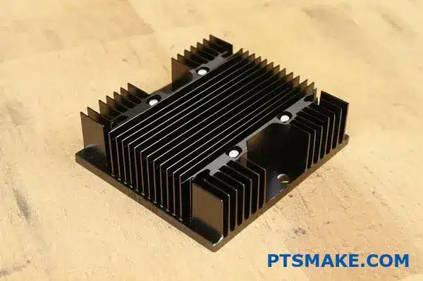
What is the primary purpose of anodizing a heat sink?
Anodizing a heat sink serves two key functions. It’s not just for looks or basic protection. Its main benefit is improving thermal performance.
Boosting Heat Radiation
A bare aluminum surface is a poor heat radiator. Anodizing, especially in black, drastically changes this. It boosts the surface’s ability to radiate heat away.
Beyond Thermal Performance
This process also creates a hard, protective layer. This layer protects against corrosion and offers electrical insulation. This adds durability and safety.
| Feature | Bare Aluminum | Black Anodized Aluminum |
|---|---|---|
| Heat Radiation | Poor (Low Emissivity) | Excellent (High Emissivity) |
| Corrosion Resistance | Low | High |
| Electrical Insulation | None | Good |
Anodizing offers more than a simple surface treatment. It fundamentally changes the heat sink’s properties. This improves both its performance and its reliability. It’s a vital step for any high-quality extruded heat sink.
How Anodizing Supercharges Heat Radiation
Heat sinks lose heat mainly through convection. But radiation is also a key factor. The anodized layer has a much higher surface emissivity5 than raw aluminum. This allows it to radiate heat more effectively into the surroundings.
The Power of Black
Black anodizing is the most popular choice for a good reason. Dark, matte surfaces are best for radiating thermal energy. A black anodized heat sink often performs much better than a bare one because of this.
| Surface Finish | Typical Emissivity Value |
|---|---|
| Polished Aluminum | ~0.05 |
| Raw Extruded Aluminum | ~0.09 |
| Black Anodized Aluminum | ~0.85 – 0.95 |
The Protective Shield of Anodizing
Beyond just cooling, the anodized layer is a strong shield. It becomes part of the aluminum, not just a coating.
Fighting Corrosion
This layer resists corrosion and abrasion very well. This extends the life of the heat sink, especially in tough environments. It keeps the part working for years.
Electrical Insulation Properties
The aluminum oxide from anodizing is a great electrical insulator. It prevents short circuits if the heat sink touches other electronic parts. This is a key safety feature.
Anodizing a heat sink is a dual-purpose process. It significantly boosts radiative cooling, particularly with black finishes. It also adds a robust layer for corrosion resistance and electrical insulation, ensuring both high performance and long-term durability for the component.
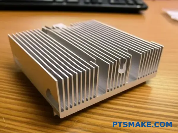
What are the common extruded heat sink profile types?
Choosing the right extruded heat sink profile is crucial. It directly impacts thermal performance. The design isn’t just about looks; it’s about physics.
Let’s explore the three primary designs you’ll encounter. Each serves a different purpose.
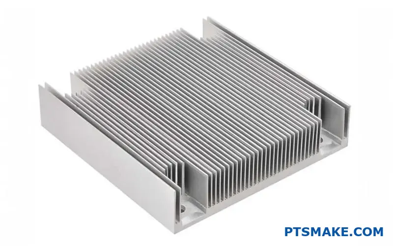
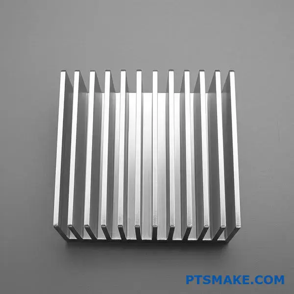
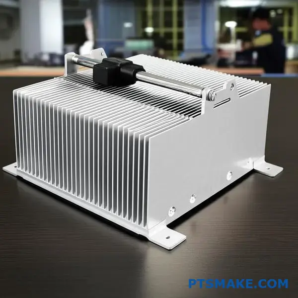
Linear/Straight Fin Profiles
This is the most common and cost-effective design. Fins run parallel to each other. They are ideal for applications with consistent, directional airflow.
Flared Fin Profiles
Here, the fins are angled outwards. This design reduces air resistance and improves airflow, especially in natural convection environments.
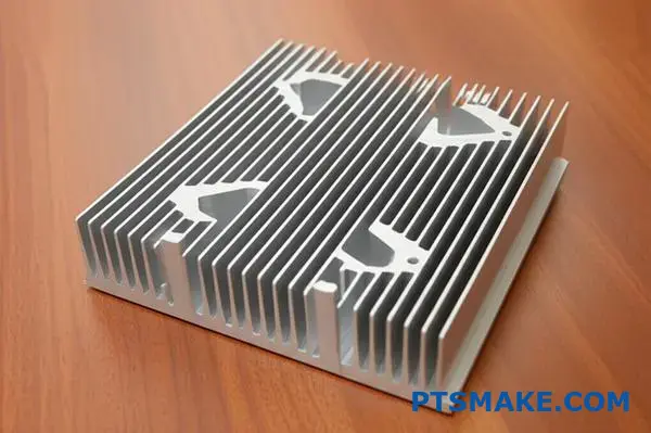
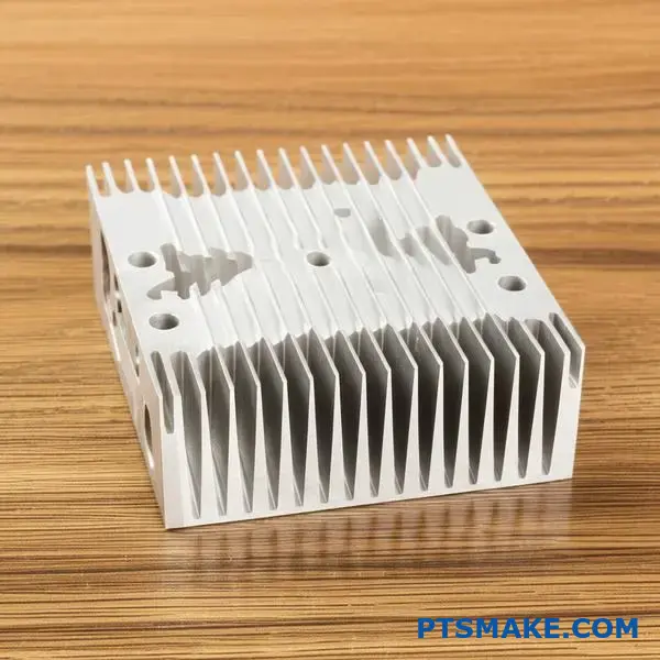
Castellated/Interlocking Fin Profiles
These profiles have fins with cross-cuts. This breaks up the airflow boundary layer, promoting turbulence and improving cooling from multiple directions.
| Profile Type | Key Feature | Best For |
|---|---|---|
| Linear/Straight | Simple, parallel fins | Forced convection (fans) |
| Flared | Angled fins | Natural convection |
| Castellated | Cross-cut fins | Multi-directional airflow |
Understanding the trade-offs of each profile helps in making an informed decision. It’s not always about picking the most complex design. The environment dictates the best solution.
In-Depth Look: Linear/Straight Fins
Advantages & Applications
Their simple geometry makes them easy to manufacture. This leads to lower costs and faster production times. We often recommend this for projects with a dedicated fan or ducted airflow, where performance is predictable and reliable.
Disadvantages
In natural convection, densely packed straight fins can trap heat. They can choke off airflow if not spaced correctly. This reduces their overall efficiency without forced air.
In-Depth Look: Flared Fins
Advantages & Applications
Flared fins excel where space is open and air moves naturally. The flare lowers air pressure drop. It also helps disrupt the thermal boundary layer6, improving heat exchange with the surrounding air. They are great for passive cooling systems.
Disadvantages
The extrusion process is slightly more complex than for straight fins. This can mean a minor increase in tooling cost. The overall footprint may also be larger.
In-Depth Look: Castellated/Interlocking Fins
Advantages & Applications
These are specialized for complex environments. The cuts create turbulence, which enhances heat transfer. They work well in applications where airflow direction is unpredictable or comes from multiple angles.
Disadvantages
The increased surface area comes at the cost of a higher pressure drop. This can be a problem for low-power fans. At PTSMAKE, we carefully model the airflow to ensure this profile provides a net benefit.
| Profile | Thermal Performance | Cost Factor | Ideal Airflow |
|---|---|---|---|
| Linear/Straight | Good (Forced) | Low | Unidirectional |
| Flared | Excellent (Natural) | Low-Medium | Natural/Low-speed |
| Castellated | Very Good (Complex) | Medium | Multi-directional |
Choosing the right profile is a balance. Straight fins are versatile workhorses. Flared fins are ideal for fanless systems. Castellated profiles solve complex airflow challenges, but require careful analysis to justify their use. Each has its place in effective thermal management.
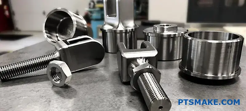
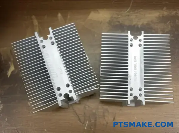
What types of secondary machining operations are commonly performed?
Extrusion creates a uniform profile. But the raw, long piece is rarely the final product. Secondary machining is what turns it into a functional component.
This involves several key steps. We start by cutting the extrusion to a precise length. Then, we often drill and tap holes for mounting.
Finally, more complex CNC machining adds specific features. These operations are crucial for creating a finished part like an extruded heat sink.
| Operation | Primary Goal |
|---|---|
| Cutting to Length | Achieve specific part dimensions |
| Drilling/Tapping | Add mounting holes for assembly |
| CNC Machining | Create custom cutouts and features |
| Fly-Cutting | Improve surface flatness |
An extruded profile fresh from the die is just a starting point. At PTSMAKE, we know that the real value comes from these secondary operations. Each step adds precision and prepares the part for its final application.
Cutting to Length
The first step is always cutting. Extrusions are produced in long sections. We use precision saws to cut each piece to the exact length specified in the design. This foundational step ensures the part fits perfectly.
Drilling and Tapping Mounting Holes
Most parts need to be attached to something else. We drill holes for screws and bolts. Tapping then adds threads inside these holes. This allows for secure and repeatable assembly. Without this, the part can’t be integrated.
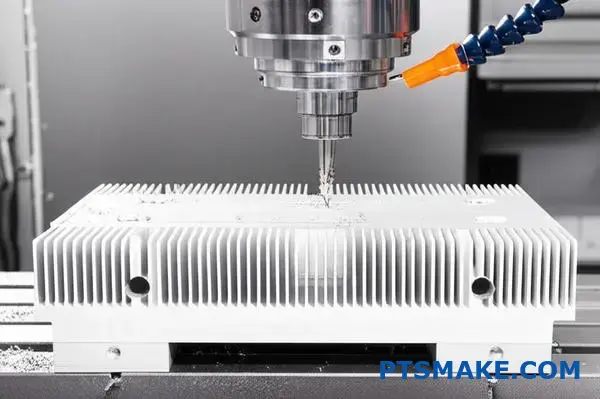
CNC Machining for Component Cutouts
Modern designs require complex features. CNC milling allows us to create pockets, slots, and custom cutouts. This is essential for fitting electronics, connectors, or other components onto the part.
Fly-Cutting for Improved Flatness
For parts like an extruded heat sink, flatness is critical. Fly-cutting shaves a micro-thin layer from the base. This process achieves a high degree of coplanarity7, ensuring maximum surface contact for heat transfer.
| Process Necessity | Impact on Final Product |
|---|---|
| Cutting | Defines the basic form factor. |
| Drilling/Tapping | Enables mechanical assembly. |
| CNC Cutouts | Allows for system integration. |
| Fly-Cutting | Optimizes thermal or mechanical performance. |
Post-extrusion machining is non-negotiable for creating functional parts. These secondary operations provide the critical features and precision needed for a raw profile to become a reliable component ready for assembly in your final product.
How do surface finish standards (e.g., anodizing types) vary?
Anodizing is not a single process. The specific type you select dramatically alters your part’s final properties. It impacts durability, color, and even cost.
Type II vs. Type III Anodizing
The primary difference is coating thickness and hardness. Type II is a conventional, decorative finish. Type III, or hardcoat, is for performance.
| Anodizing Type | Common Name | Typical Thickness |
|---|---|---|
| Type II | Conventional/Clear | 0.0002" – 0.001" |
| Type III | Hardcoat | 0.001" – 0.004" |
This choice is critical for your component’s lifespan and function.
Key Performance Differences
Choosing the right anodizing type goes beyond looks. It’s a critical engineering decision that affects performance and longevity. We always guide our partners at PTSMAKE through these choices.
Durability and Hardness
Type III hardcoat anodizing creates a much denser, harder layer. This offers superior abrasion resistance for parts in high-wear environments. Type II is softer but provides excellent corrosion protection for most applications.
Thermal and Electrical Properties
Anodizing choices impact thermal emissivity. This is crucial for parts like an extruded heat sink. A black anodized finish, whether Type II or III, radiates heat more effectively than a clear or colored one.
Both types improve insulation. The thicker Type III coating provides a much higher dielectric strength8. This is a key benefit for electronics enclosures or components needing electrical isolation.
Color and Cost Considerations
Type II anodizing is easier to dye, offering a wide spectrum of colors. Type III’s density makes dyeing harder, often resulting in darker, muted tones.
The hardcoat process is more energy-intensive and time-consuming, making Type III more expensive than Type II.
| Feature | Type II (Conventional) | Type III (Hardcoat) |
|---|---|---|
| Durability | Good corrosion resistance | Excellent abrasion & wear resistance |
| Insulation | Moderate | High |
| Color Options | Wide Range | Limited, often dark |
| Cost | Lower | Higher |
Choosing wisely means balancing your application’s technical needs with your budget.
Choosing between anodizing types involves trade-offs. Type II is great for cosmetic parts needing corrosion resistance. Type III delivers superior hardness and insulation for demanding functional applications. Your final decision depends on balancing performance needs with your budget.
What are the typical design rules for a custom extrusion profile?
Designing a new extrusion profile requires balance. You need to meet functional needs. But it must also be manufacturable.
Following some basic rules is key. These guidelines ensure your design can be produced efficiently. This avoids costly tool modifications later.
Key Guidelines for a New Profile
We focus on four main areas. These are wall thickness, aspect ratio, corner radii, and tongue ratio. Getting these right from the start is crucial for success.
| Design Rule | General Guideline |
|---|---|
| Wall Thickness | Keep it uniform |
| Aspect Ratio | Aim for low ratios |
| Corner Radii | Avoid sharp corners |
| Tongue Ratio | Follow material limits |
These rules help manage metal flow. They also reduce stress on the extrusion die.
Diving Deeper into Profile Design Rules
Let’s explore these concepts further. Understanding them prevents common issues. At PTSMAKE, we guide our clients through these details. This ensures a smooth transition from design to production.
Aspect Ratio and Wall Thickness
A high aspect ratio can cause problems. It means one dimension is much larger than another. This can lead to uneven material flow and warping.
Consistent wall thickness is vital. Drastic changes in thickness create uneven cooling. This results in internal stress and distortion in the final part. We always recommend gradual transitions if thickness variation is unavoidable.
Corner Radii
Sharp internal corners are difficult to extrude. They create high-stress points on the die. This can lead to die breakage and slow production.
Adding a generous radius is better. It improves metal flow and increases the tool’s lifespan. A simple rule is to make the inside radius at least half the wall thickness. For complex parts like an extruded heat sink9, proper radii are essential for performance and durability.
Understanding the Tongue Ratio
The tongue ratio is a critical factor. It defines the relationship between the width and height of a narrow gap or channel in the die.
A high ratio makes the "tongue" on the die weak. This metal feature can bend or break under the immense pressure of extrusion. Adhering to material-specific limits for this ratio is non-negotiable for robust tooling.
Following these design rules ensures your profile is manufacturable and cost-effective. Key considerations include maintaining uniform wall thickness, using generous corner radii, and managing aspect and tongue ratios. This approach prevents production delays and tooling failures, ensuring a high-quality final product.
How do you properly specify a custom heat sink for manufacturing?
A detailed drawing is your primary communication tool. It tells the manufacturer exactly what to build. Getting this document right is critical.
It prevents costly errors and saves production time. This simple checklist covers all the essentials.
Following it helps ensure your custom extruded heat sink is made correctly. Let’s make your design a reality, just as you planned.
Profile Drawing: The Blueprint
Your drawing’s profile view is the most critical part. It must show the cross-section of the extrusion. Every feature needs a dimension.
This includes fin height, fin thickness, and base thickness. Don’t forget to include tolerances for all critical dimensions. This ensures the heat sink fits perfectly into your assembly.
Material and Length: The Foundation
Material Specification
The material choice directly impacts performance. You must specify the exact aluminum alloy and temper. For example, "Alloy 6063-T5" is common for heat sinks.
This detail is crucial. It defines the part’s strength, machinability, and Thermal Conductivity10. Different alloys cool differently.
| Alloy | Thermal Conductivity (W/mK) | Key Characteristic |
|---|---|---|
| 6061-T6 | 167 | Good strength, machinable |
| 6063-T5 | 201 | Excellent for extrusion, good finish |
| 1050A | 229 | High purity, best conductivity |
Cut Length and Tolerance
You also need to specify the final cut length of the part. Just as important is the tolerance on that length. A spec like "100mm ±0.2mm" is clear and actionable for manufacturing.
Getting the core specifications right is essential. Your profile drawing, material choice, and length dimensions form the foundation. These details directly impact thermal performance, cost, and final assembly, setting your project up for success.
Secondary Operations: Adding Features
Most heat sinks require extra machining after extrusion. These secondary operations must be clearly defined.
This includes drilling mounting holes, tapping threads, or milling pockets. Every feature needs precise location data and tolerances on the drawing. This removes any guesswork for the machinists.
Final Touches: Surface Finish
The surface finish protects the heat sink and can improve performance. You must specify it clearly. "Black Anodize" is a common request for both appearance and corrosion resistance.
Be specific. A complete callout looks like this: "Black Anodize per MIL-A-8625, Type II, Class 2." This tells us everything we need to know.
| Specification | Description | Common Example |
|---|---|---|
| Standard | The governing specification | MIL-A-8625 |
| Type | Defines the anodizing process | Type II (Sulfuric acid) |
| Class | Defines the color | Class 2 (Dyed, e.g., Black) |
This level of detail ensures the finish is consistent and meets your requirements.
This checklist is your blueprint for a successful project. A complete, unambiguous drawing is the most important document you can provide.
At PTSMAKE, we rely on clear drawings to deliver high-quality parts that meet your exact needs. It ensures a smooth process from quote to production.
Use this checklist on your next project. It will help you communicate clearly with your manufacturing partner, ensuring precision and preventing delays.
Analyze a cooling design for a high-power LED light.
Let’s tackle a common challenge: cooling a 100W COB LED for an industrial high-bay light. Passive cooling is the goal for reliability.
The core of our solution is an extruded heat sink. This method is cost-effective and highly efficient for this application. We must choose the right profile and orientation.
Passive vs. Active Cooling
| Feature | Passive Cooling | Active Cooling |
|---|---|---|
| Reliability | Very High | Lower (moving parts) |
| Maintenance | None | Required (fans) |
| Cost | Lower | Higher |
| Noise | Silent | Audible |
Our design will focus on maximizing performance without fans.
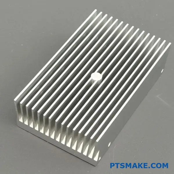
Heat Sink Selection and Design
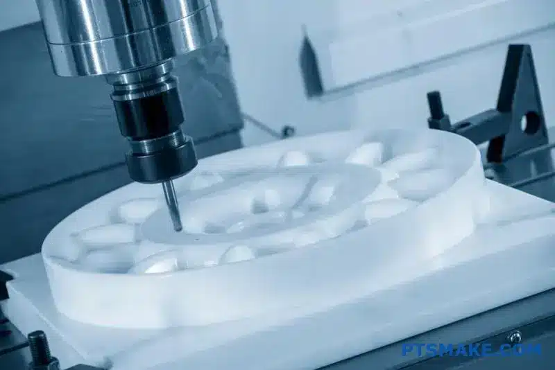
For a 100W LED, a large aluminum extruded heat sink is necessary. We opt for a profile with tall, thin fins. This design maximizes the surface area available for heat dissipation. At PTSMAKE, we often CNC machine custom profiles for optimal performance.
The orientation is critical. Fins must be vertical. This allows heated air to rise freely, creating an airflow that pulls cooler air from below. Placing it horizontally would trap heat. The goal is to minimize overall Thermal Resistance11 from the LED to the air.
TIM and Mounting Method
We specify a high-performance thermal pad as the Thermal Interface Material (TIM). While paste can offer slightly better performance initially, pads are more reliable and consistent in industrial environments. They don’t dry out or pump out over time.
The mounting method involves four screws. These screws will be at the corners of the COB LED’s mounting base. This ensures even pressure across the TIM. It creates a solid, reliable thermal connection.
Core Design Trade-Offs
| Factor | Decision & Justification |
|---|---|
| Performance vs. Cost | Chose a larger extruded profile. Higher initial cost is offset by long-term reliability and zero maintenance. |
| Size vs. Aesthetics | Prioritized size for thermal performance. The high-bay light’s industrial setting makes aesthetics secondary. |
| Simplicity vs. Complexity | A passive system is simpler. It avoids the failure points of active systems like fans, crucial for industrial use. |
This passive solution ensures long-term reliability for the high-power LED light. The design choices prioritize performance and durability in an industrial setting by using a specific extruded heat sink, TIM, and mounting method.
Unlock Superior Custom Extruded Heat Sink Solutions with PTSMAKE
Ready to elevate your project with expertly engineered extruded heat sinks? Contact PTSMAKE today for a fast, detailed quotation—our team of precision manufacturing specialists is eager to meet your exact demands in design, quality, and performance. Send us your inquiry now and experience true manufacturing partnership!

Discover how directional material properties can influence thermal management in your designs. ↩
Learn how different heat treatments transform the final strength and performance of aluminum alloys. ↩
Understand how this effect impacts your design’s final dimensional accuracy and thermal efficiency. ↩
Understand uniform temperature’s role in ideal thermal analysis. ↩
Learn how this property is crucial for improving your heat sink’s radiative cooling performance. ↩
Learn how this invisible air layer affects heat dissipation and why fin design is crucial for breaking it. ↩
Learn how surface flatness directly impacts performance and reliability. ↩
Discover how this electrical property can protect your sensitive electronic components from failure. ↩
Learn how this critical ratio impacts tool strength and the manufacturability of your profile. ↩
Learn how material choice impacts your heat sink’s cooling efficiency and overall performance. ↩
Learn how this key metric quantifies heat dissipation performance in thermal management. ↩