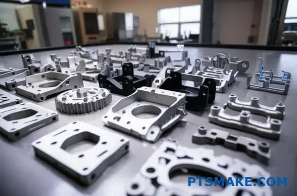
Many manufacturers struggle with producing complex metal parts that require intricate geometries and tight tolerances. Traditional machining becomes costly and time-consuming when dealing with high-volume production of small, detailed components.
Metal Injection Molding (MIM) combines the design flexibility of plastic injection molding with the strength and durability of metal parts, enabling cost-effective mass production of complex geometries that would be expensive or impossible to machine conventionally.
After working with MIM projects at PTSMAKE, I’ve learned that success depends on understanding which parts benefit most from this process and how to optimize the entire workflow from design to production.
What defines a part as ‘ideal’ for MIM?
Deciding if Metal Injection Molding (MIM) is right for your project isn’t always simple. It’s a balance of several key factors. Get one wrong, and it might not be cost-effective.
At PTSMAKE, we see the best results when a part hits a specific sweet spot.
Core Characteristics for MIM
The ideal part often has complex geometry. It’s also typically small to medium in size. This is where MIM truly shines. High production volumes are crucial to offset initial tooling costs.
Material and Production Volume
Materials that are tough to machine, like stainless steels or titanium, are perfect candidates. Our metal injection molding services excel with these.
| Characteristic | Ideal for MIM | Less Ideal for MIM |
|---|---|---|
| Complexity | High (intricate details, thin walls) | Low (simple blocks, rods) |
| Size | Small to Medium (<100g) | Large and heavy |
| Volume | High (10,000+ parts/year) | Low (prototypes, one-offs) |
| Material | Hard-to-machine metals | Easily machined alloys |

A Deeper Look at Ideal Candidates
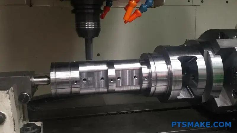
Let’s break down why these factors matter so much. Complexity is a major cost driver in traditional CNC machining. Every feature often requires a separate setup or tool.
MIM creates complex shapes in a single step. This eliminates multiple machining operations. It dramatically reduces the cost per part, but only at high volumes.
Consider medical surgical tools. They have intricate handles and functional ends. Machining them from a solid block of stainless steel is incredibly slow and wasteful. MIM produces the net shape quickly.
The Cost-Benefit Analysis
The initial mold investment is significant. This is why low-volume projects are not a good fit. The cost of the mold must be spread across thousands of parts to make sense.
In our experience with clients, the breakeven point is often clear. We analyze the part’s geometry and material needs to make a recommendation. The process uses a specialized feedstock1 of metal powder and binder.
A great example is firearm components. Parts like triggers and sights have complex internal features. MIM produces these features consistently with excellent surface finish, requiring minimal secondary operations.
| Process | Key Advantage | Best For… |
|---|---|---|
| MIM | Cost-effective complex shapes at scale | High-volume, small, intricate parts |
| CNC Machining | High precision, material flexibility | Prototypes, low-volume, large parts |
In short, the ideal MIM part combines complex geometry, a suitable material, and high production volume. This combination unlocks significant cost savings and design freedom compared to traditional manufacturing methods.
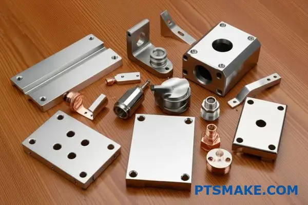
How does MIM compare to traditional CNC machining?
Choosing between MIM and CNC machining is a critical decision. It directly impacts your project’s cost, speed, and final quality.
Let’s break down the core differences. Understanding these factors will help you select the right manufacturing process for your specific needs.
Key Comparison Factors
| Factor | Metal Injection Molding (MIM) | CNC Machining |
|---|---|---|
| Best For | High-volume, complex parts | Prototypes, low-to-mid volume |
| Initial Cost | High (mold tooling) | Low (no tooling) |
| Per-Part Cost | Low at scale | Higher, more consistent |
| Material Waste | Minimal | Significant |
A Deeper Look at Cost and Complexity
The most significant financial difference is the initial investment. MIM requires a substantial upfront cost to create the injection mold. This makes it impractical for one-off prototypes or very small production runs.
CNC machining, on the other hand, is a "tooling-free" process. We can start manufacturing directly from a 3D CAD file. This offers incredible flexibility for design iterations and faster initial part delivery.
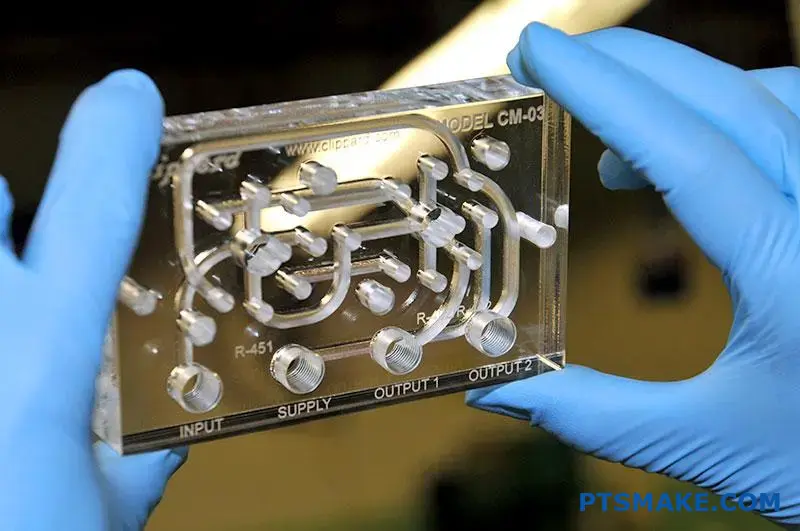
When it comes to part complexity, MIM truly shines. It excels at producing small, intricate geometries that would be difficult or costly to machine. Features like internal threads or tiny cross-holes are easily formed during the molding stage.
Our metal injection molding services2 are often used for these types of components. The subsequent sintering stage is crucial for achieving the final material properties. CNC can also create complex parts, but it might require multiple machine setups or specialized cutting tools, increasing labor and cost.
Scenario-Based Process Selection
| Scenario | Recommended Process | Why? |
|---|---|---|
| 10 Prototypes | CNC Machining | No tooling cost, fast turnaround. |
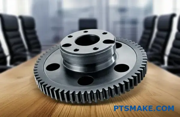
| 50,000 Small Gears | Metal Injection Molding | Lower per-part cost at scale. |
| Large, Simple Bracket | CNC Machining | Part size is better for machining. |
| Intricate Medical Tool | Metal Injection Molding | Superior for complex, small shapes. |
Choosing correctly is crucial. CNC machining provides flexibility for prototypes and low volumes. MIM delivers unmatched cost-effectiveness and speed for mass-producing complex parts, despite the high initial tooling investment. Both are powerful, but they solve different manufacturing challenges.
What are the fundamental limitations of the MIM process?
Metal Injection Molding (MIM) is a powerful technology. It excels at producing small, complex metal parts in high volumes. However, it’s not a universal solution.
Understanding its limitations is key to a successful project. These constraints often revolve around size, cost, and lead times. Making the right choice means knowing these trade-offs from the start.
Key Constraints at a Glance
Here’s a quick breakdown of the primary challenges.
| Constraint | Primary Impact | Best Use Case |
|---|---|---|
| Part Size & Weight | Limited to smaller components | Small, intricate geometries |
| Tooling Cost | High initial investment | High-volume production runs |
| Lead Time | Longer for first article | Projects with stable, long-term demand |
| Tolerances | Can require secondary ops | When +/-0.5% is acceptable |
The most significant barrier for many is the upfront tooling cost. The molds for MIM are complex and must withstand high pressures. This makes them a substantial initial investment.
This cost is only justified by high production volumes. For low-volume needs, the per-part cost becomes too high compared to alternatives like CNC machining. At PTSMAKE, we always help clients analyze their break-even point.
The Challenge of Time and Precision
Initial lead times can also be a hurdle. Designing, manufacturing, and validating a MIM mold takes time. This process can be much longer than setting up a CNC machining run.
Precision is another critical factor. The process involves significant sintering shrinkage3, which must be precisely controlled. Standard tolerances are excellent, but achieving extremely tight specifications often requires secondary operations.
Balancing Speed and Accuracy
Based on our project experience, here’s what you can typically expect.
| Operation | Standard MIM Tolerance | Post-Machining Tolerance |
|---|---|---|
| Dimensional Accuracy | ±0.3% to ±0.5% | As low as ±0.025 mm |
| Surface Finish | 1.6-3.2 µm Ra | <0.8 µm Ra |
| Feature Complexity | High | Very High |
Our expertise in metal injection molding services allows us to predict these outcomes accurately. We plan for any necessary secondary steps from the beginning.
In short, MIM is not for every part. The process is constrained by part size, high initial tooling costs, and longer setup times. Achieving the tightest tolerances may also require extra processing steps, which must be factored into the plan.
What major categories of materials can be processed by MIM?
Metal Injection Molding (MIM) is incredibly versatile. It supports a wide range of materials. This allows us to create complex parts for different industries. The most common materials fall into three main groups.
Ferrous Alloys
These are iron-based materials. They are popular for their strength and cost-effectiveness.
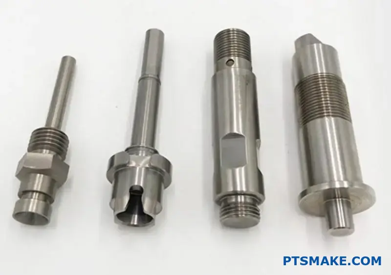
Stainless Steels
Examples like 316L and 17-4 PH are widely used. They offer excellent corrosion resistance, making them ideal for medical and marine parts.
Tool Steels
These are known for hardness and durability. We often use them for cutting tools and high-wear components.
Non-Ferrous & Specialty Materials
This group includes lighter metals and highly specialized options.
Titanium Alloys
These are light yet strong. They are perfect for aerospace and medical implants where weight is critical.
Tungsten Heavy Alloys
These materials are extremely dense. They are used for radiation shielding and balancing weights.
A quick comparison of common MIM materials:
| Material Family | Key Property | Common Application |
|---|---|---|
| Stainless Steel | Corrosion Resistance | Surgical tools, watch cases |
| Tool Steel | Hardness | Cutting tool inserts |
| Titanium Alloys | Strength-to-Weight | Aerospace brackets |
| Tungsten Alloys | High Density | Radiation shielding |
When selecting a material, we must look beyond just the final properties. The entire process, from powder selection to sintering, is tailored to the material. This ensures the final part meets exact specifications.
The Nuances of Material Processing
The choice of material directly impacts the process parameters. For instance, titanium requires a controlled atmosphere during sintering to prevent oxidation. This adds complexity compared to some stainless steels.
The binder system is also critical. It must be compatible with the metal powder. The removal of this binder is a multi-step process. It often involves a chemical or solvent bath followed by thermal debinding, a process also known as Pyrolysis4. Any residue can affect the final part’s density and strength.
Application-Driven Selection
In our projects at PTSMAKE, the application always dictates the material. A part for a consumer electronic device has very different needs than a component for an automotive engine. Our expertise in metal injection molding services helps clients navigate these choices.
We often evaluate materials based on several factors:
| Factor | Description | Example |
|---|---|---|
| Mechanical Strength | The ability to withstand stress. | A load-bearing bracket. |
| Corrosion Resistance | Resistance to environmental decay. | A part used in marine environments. |
| Thermal Conductivity | How well it transfers heat. | A heat sink for electronics. |
| Biocompatibility | Not harmful to living tissue. | A medical implant. |
This detailed approach ensures we deliver components that perform reliably.
MIM’s strength lies in its material diversity. From common stainless steels to specialized titanium and tungsten alloys, the process accommodates a vast range of engineering needs, with material selection tailored to each specific application’s demands.
How do part geometries get classified for MIM suitability?
To decide if Metal Injection Molding (MIM) is the right choice, we classify parts by their geometry. This simple step helps us quickly see if a part is a good fit. It saves time and prevents costly design changes later.
Key Classification Features
We generally sort parts into four main categories. Each one has different things to consider for the MIM process. This system is the foundation of our initial project review.
| Classification | Core Design Feature | General MIM Suitability |
|---|---|---|
| Type 1 | Complex 3D Surfaces | Excellent |
| Type 2 | Internal or External Threads | Good, with specific guidelines |
| Type 3 | Varying Wall Thicknesses | Challenging, requires careful design |
| Type 4 | Assembly Consolidation | Ideal, a key strength of MIM |
This framework helps streamline our conversation.
Let’s break down these classifications. Each type presents unique opportunities for engineers. Understanding them helps you design parts that take full advantage of what MIM offers.
Type 1: Complex 3D Surfaces
Parts with intricate curves and organic shapes are prime candidates for MIM. This includes components for medical or aerospace use. Machining these shapes from a solid block of metal is extremely time-consuming and expensive. MIM produces these geometries efficiently in one process.
Type 2: Components Requiring Threads
MIM can mold standard internal or external threads directly into the part. This capability saves a lot of money by avoiding secondary tapping or machining operations. It also shortens the overall production time for threaded components.
Type 3: Parts with Varying Wall Thicknesses
This aspect requires careful attention. Sudden shifts from thick to thin sections can lead to defects. In our projects at PTSMAKE, we advise on designing smooth transitions between different wall thicknesses. This ensures the part fills and sinters uniformly.
Type 4: Assembly Consolidation
MIM is incredibly effective at turning a multi-part assembly into a single, solid component. This move reduces assembly costs and simplifies your supply chain. It also results in a stronger part with excellent isotropic properties5. Our metal injection molding services excel at identifying these cost-saving opportunities.
In short, this classification system provides a clear path. By evaluating a part’s surfaces, threads, wall thickness, and potential for consolidation, we can quickly determine if MIM is the most effective and economical manufacturing solution.
What types of secondary operations are common for MIM parts?
Sintered MIM parts are already near-net-shape. But they often need extra steps. These secondary operations help parts meet exact design requirements.
At PTSMAKE, we see these processes as vital. They ensure your components perform perfectly in their final application. It is a crucial part of our comprehensive metal injection molding services.
Common Post-Sintering Processes
We can group these finishing steps into four main types. Each one serves a distinct purpose.
| Operation Type | Primary Purpose |
|---|---|
| Heat Treatment | To improve mechanical properties like hardness. |
| Surface Finishing | To enhance appearance and corrosion resistance. |
| Machining | To meet critical dimensional tolerances. |
| Joining | To create assemblies from multiple parts. |
After a part exits the sintering furnace, the real customization begins. Each secondary operation is chosen to meet a specific engineering goal. It’s how we refine a component to fit your application perfectly.
Heat Treatment for Strength
Heat treatment modifies the part’s internal structure. Processes like quenching and tempering can significantly increase hardness and strength. This is essential for parts that will face high wear and stress during their service life.
Surface Finishing for Durability and Aesthetics
This category covers many treatments. Plating with materials like nickel or chrome adds excellent wear and corrosion resistance. Coatings can provide unique properties like lubricity. We also perform polishing for a cosmetic, mirror-like finish. Another important process is passivation6.
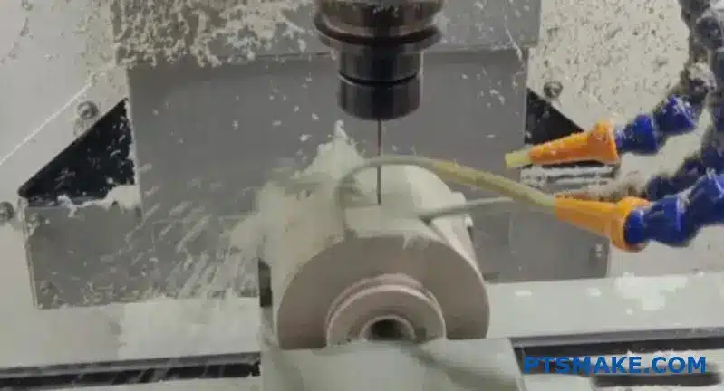
Machining for Critical Tolerances
MIM achieves impressive tolerances. However, some designs require even greater precision. We use CNC machining for features that must be perfect. At PTSMAKE, we often drill holes, tap threads, or grind surfaces post-sintering.
Joining Techniques for Assemblies
Sometimes a final product is made of several parts. We use joining methods to create robust assemblies.
| Joining Method | Best For |
|---|---|
| Laser Welding | Precise, strong bonds with minimal heat impact. |
| Brazing | Joining dissimilar metals or complex shapes. |
| Co-sintering | Bonding green parts together in the furnace. |
These techniques allow for the creation of more intricate and functional final products.
Post-sintering operations are essential for customizing MIM parts. They enhance everything from mechanical strength and corrosion resistance to achieving critical dimensions. These steps ensure the final component fully meets all your engineering requirements and application needs.
How does part complexity segment the MIM service market?
The Metal Injection Molding (MIM) market isn’t one-size-fits-all. It’s clearly segmented by the technical challenge of the parts. Your choice of partner depends heavily on this.
Some providers focus on simple, high-volume components. Their strength is efficiency and cost-effectiveness for less demanding applications.
On the other end, you find specialists. These companies tackle highly complex, tight-tolerance parts. They serve critical industries where failure is not an option.
Provider Specialization
| Feature | High-Volume, Simple Parts | Low-Volume, Complex Parts |
|---|---|---|
| Primary Goal | Cost Efficiency | Precision & Performance |
| Typical Industries | Consumer Goods, General Hardware | Aerospace, Medical, Automotive |
| Tooling Strategy | Optimized for speed | Built for extreme precision |
| Part Price | Lower | Higher |
Providers specializing in simple parts excel at mass production. Their processes are streamlined for speed and minimal cost per part. This is perfect for components like brackets or fasteners where tolerances are generous and the design is straightforward.
In contrast, a specialist in complex parts operates differently. At PTSMAKE, we focus here. The engineering challenge is the main driver. This involves intricate geometries, thin walls, and extremely tight tolerances required for medical implants or aerospace engine components.
Success in this high-end segment demands more than just molding. It requires deep expertise in material science and process control. For example, controlling the sintering parameters7 becomes incredibly critical. Small variations can drastically affect the final part’s mechanical properties and dimensional accuracy.
Our experience in past projects shows that this segment requires a true partnership. We often work closely with clients from the design phase to ensure manufacturability. This collaborative approach is essential when providing advanced metal injection molding services for critical applications.
Technical Requirements by Segment
| Requirement | Simple Part Provider | Complex Part Provider |
|---|---|---|
| Engineering Support | Basic DFM feedback | In-depth collaborative design |
| Quality Control | Standard calipers, visual checks | CMM, CT scanning, SPC |
| Tooling Expertise | High-speed, multi-cavity | Complex actions, tight tolerances |
| Material Expertise | Standard alloys | Custom feedstock, exotic materials |
The MIM market is divided. High-volume providers prioritize cost and speed for simple parts. Specialists, on the other hand, deliver precision and reliability for complex, mission-critical components, demanding advanced engineering and quality control from start to finish.
How do you select the right material for a client’s part?
Selecting the right material is a critical first step. It ensures the final part functions perfectly and is cost-effective. My process always begins with understanding your specific needs. This foundation prevents costly errors later.
Key Client Requirements
We start by defining the part’s essential properties. This involves a detailed discussion to capture every constraint and goal. We document these needs clearly.
| Requirement | Description |
|---|---|
| Mechanical Strength | The load the part must withstand. |
| Corrosion Resistance | Exposure to moisture or chemicals. |
| Hardness | Resistance to wear and abrasion. |
| Target Cost | The budget for each part. |
This systematic approach ensures we never miss a critical detail.
A Deeper Dive into Material Trade-offs
Choosing a material is rarely straightforward. It often involves balancing competing properties. You can’t always have maximum strength, maximum corrosion resistance, and minimum cost in one alloy. The real skill is in finding the optimal balance for your application.
Comparing Candidate Materials
In past projects at PTSMAKE, we’ve created matrices to compare materials. This visual tool helps clients see the trade-offs clearly. For example, a stainless steel might offer great corrosion resistance but come at a higher cost than a low-alloy steel.
| Material | Relative Strength | Relative Corrosion Resistance | Relative Cost |
|---|---|---|---|
| 17-4 PH Stainless Steel | High | High | Medium |
| 316L Stainless Steel | Medium | Very High | High |
| 4140 Low-Alloy Steel | Very High | Low | Low |
Beyond the Datasheet: Processability
A material’s datasheet doesn’t tell the whole story. We must also consider its processability in MIM. Some alloys flow better into complex molds. Others might have higher, less predictable shrinkage rates during sintering. We also analyze properties like the Coefficient of Thermal Expansion8. This impacts how a part behaves with temperature changes, especially if it’s part of an assembly. Our experience with metal injection molding services helps us predict these behaviors.
A structured approach to material selection is crucial. It involves defining clear requirements, carefully weighing the trade-offs between candidate materials, and considering the practicalities of the manufacturing process. This ensures the final part meets both performance specifications and budget constraints.
How do you calculate the true cost of a MIM part?
Calculating the true cost of a MIM part goes beyond a simple quote. It’s about understanding the fully-burdened cost. This ensures there are no surprises later.
This true cost combines obvious expenses with hidden ones. You must account for direct costs like materials and machine time. But indirect costs like tool amortization and scrap rates are just as important for an accurate picture.
Key Cost Categories
| Direct Costs | Indirect Costs |
|---|---|
| Feedstock | Tooling Amortization |
| Machine Time | Scrap Rate |
| Labor | Quality Inspection |
| Energy | Overhead |

To find the true cost, we need a simple but comprehensive model. It’s not just about adding up numbers; it’s about a clear perspective on every factor contributing to the final price per part.
Building the Cost Model
The basic formula is:
True Cost per Part = (Total Direct Costs + Total Indirect Costs) / Number of Good Parts
Let’s break down these components.
Direct Costs
These are costs directly tied to producing each part.
- Feedstock: The price of the metal powder and binder mixture.
- Machine Time: The cost to run molding, debinding, and sintering equipment.
- Labor: The wages for operators who handle the parts and machines.
Indirect Costs
These costs are shared across many projects.
- Tooling Amortization: The mold cost is spread across the expected production volume. A higher volume means a lower cost per part.
- Scrap Rate: Not every part produced is perfect. The cost of scrapped parts must be absorbed by the good ones.
- Quality Inspection: Time and equipment used for inspection add to the cost.
- Overhead: This covers rent, utilities, and administrative staff. Proper Overhead Allocation9 is critical for fair pricing in our metal injection molding services.
By looking at this full picture, you can truly evaluate a supplier’s quote. At PTSMAKE, we believe in transparency, helping you understand these factors for a successful partnership.
Calculating the fully-burdened cost means looking past the obvious. By including both direct and indirect costs, from feedstock to factory overhead, you get a true financial picture. This ensures your project is profitable and sustainable in the long run.
Evaluate a client’s machined part for conversion to MIM.
Here is a comprehensive framework we use at PTSMAKE. It helps decide if switching to MIM is the right move for your part.
We look at four key areas. This initial check gives a clear picture of the part’s potential.
Initial Assessment Checklist
| Factor | Ideal for MIM |
|---|---|
| Geometry | Complex, intricate shapes |
| Annual Volume | High (e.g., 10,000+ units) |
| Material | Standard MIM alloys |
| Tolerances | Moderate, not extremely tight |
This structured approach quickly identifies strong candidates for our metal injection molding services. It saves time and focuses our efforts effectively.
Diving into the Cost-Benefit Analysis
A full evaluation goes beyond the initial checklist. We need to look at the numbers to calculate the Return on Investment (ROI). This is where a detailed cost-benefit analysis becomes crucial.
The main trade-off is upfront tooling cost versus long-term savings on the per-part price. Machining has no tooling cost, but each part is expensive. MIM has a significant initial mold cost. However, the price per part drops dramatically.
Cost Comparison Example
Let’s break down the costs. The key is finding the breakeven point where the total cost of MIM becomes less than machining. This involves the amortization10 of the tool cost over the production run.
| Cost Component | CNC Machining | Metal Injection Molding (MIM) |
|---|---|---|
| Tooling Investment | $0 | High (e.g., $15,000 – $50,000+) |
| Per-Part Cost | High | Very Low (often 50-80% less) |
| Breakeven Volume | N/A | Typically 10,000 – 20,000+ units |
In past projects at PTSMAKE, we’ve seen clients break even within the first year. This happens when their annual volume is high enough. The long-term savings can be substantial, directly impacting their bottom line. We work closely with clients to create this analysis.
A structured evaluation framework is key. It assesses geometry, volume, material, and tolerances first. Then, a detailed cost-benefit analysis determines the financial viability and ROI, guiding the final decision.
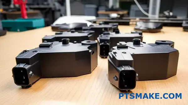
Design a complete workflow for a high-volume automotive sensor housing.
A successful project requires a solid plan. It acts as our roadmap. This plan connects every stage seamlessly. It ensures we move from design to mass production without costly delays.
From Blueprint to Production
The journey starts with a detailed kickoff. We define every requirement upfront. This clarity is crucial for success. Each phase builds upon the last.
Key Project Milestones
Here is a typical high-level plan. It shows how we structure these complex projects.
| Phase | Key Activities | Estimated Duration |
|---|---|---|
| 1. Planning | Requirement Analysis, Team Setup | 1 Week |
| 2. Design | Tool Design, DFM, Simulation | 3-4 Weeks |
| 3. Execution | Tooling, Process Setup, PQP | 5-7 Weeks |
| 4. Validation | PPAP Submission, Pilot Run | 2-3 Weeks |
| 5. Production | Ramp-Up & Automation | Ongoing |
This structure keeps everyone aligned. It makes sure we hit every critical milestone.
Integrating Critical Path Activities
A great plan integrates key activities. It doesn’t treat them as separate tasks. Tool design and process development must happen together. This synergy is where efficiency is born. At PTSMAKE, we use DFM (Design for Manufacturability) to link these two worlds from day one.
The Quality Framework: PQP and PPAP
Quality is not an afterthought. We build a Preliminary Quality Plan (PQP) during the tooling phase. This plan outlines every inspection point. It defines measurement methods and control limits.
Our quality engineers perform studies like Gage R&R11. This ensures our measurement systems are reliable before we even make the first part.
The PQP then evolves into the full Production Part Approval Process (PPAP) submission.
| PPAP Element | Description |
|---|---|
| Design Records | All drawings and specifications. |
| Process Flow Diagram | A map of the entire production process. |
| PFMEA | Analysis of potential process failures. |
| Control Plan | Document outlining quality checks. |
| MSA | Measurement System Analysis reports. |
The Ramp-Up Strategy
Once PPAP is approved, we begin the ramp-up. We start with a lower volume. This allows us to fine-tune the automated production cell. We monitor key metrics to ensure stability. Then, we scale to full capacity, meeting the high-volume demands of the automotive industry.
An integrated project plan is non-negotiable for high-volume automotive parts. It connects tool design, process development, quality assurance, and production ramp-up. This holistic approach ensures quality, mitigates risks, and guarantees a smooth launch from start to finish.
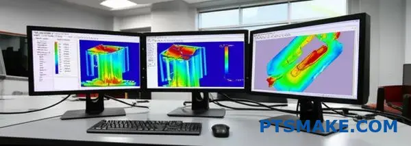
How would you use mold-flow simulation to de-risk a project?
Integrating modern technology is key. We use simulation software early in the design phase. This helps us see problems before they happen.
This proactive approach is crucial. It saves significant time and money. We don’t wait for physical prototypes to find flaws.
Predicting Potential Molding Issues
Our focus is on identifying common defects. These include air traps, weld lines, and uneven filling patterns. Simulation shows us exactly where these might occur.
Common Defects Uncovered by Simulation
| Defect Type | Risk without Simulation |
|---|---|
| Air Traps | Voids, burn marks |
| Weld Lines | Weak structural points |
| Uneven Filling | Warpage, sink marks |
We use the simulation data to make smart choices. This isn’t just theory. It directly guides our engineering decisions before any steel is cut. It’s a digital blueprint for success.
Optimizing Gate and Runner Systems
One of the first things we look at is gate location. A poorly placed gate can cause almost every common molding defect. The simulation shows us the ideal spot for smooth, even filling.
This reduces pressure and stress in the part. It also helps control how the plastic cools. We can also optimize the runner system for efficiency, saving material on each shot.
Refining Part Geometry
Sometimes, the data tells us the part design itself is the problem. We might see high stress areas or predict issues with volumetric shrinkage12. We then work with clients to adjust wall thicknesses or add fillets. These small changes have a huge impact on final quality. This detail is especially critical for complex projects, including our metal injection molding services.
Here’s how data leads to direct action:
| Simulation Finding | Design Action Taken |
|---|---|
| High Fill Pressure | Increase gate size or add more gates |
| Weld Line in Critical Area | Relocate gate to move the weld line |
| Potential for Sink Marks | Modify rib/boss design or adjust thickness |
In short, using mold-flow simulation early is a game-changer. It allows us to digitally predict and solve molding issues. We optimize gate locations and part design, ensuring a smoother production process and a higher quality final product before cutting any steel.
Start Your Metal Injection Molding Project with PTSMAKE Today
Ready to unlock new efficiency and quality for your complex, high-volume components? Contact PTSMAKE now for a tailored quote on metal injection molding services. Our expert team will respond quickly, helping you save time, reduce costs, and achieve manufacturing excellence from prototype to production.

Learn about this essential MIM material to optimize your part design for manufacturing. ↩
Learn about this thermal process that fuses metal particles into a solid, high-density part. ↩
Learn how this critical stage impacts the final precision and strength of your MIM parts. ↩
Understand the critical debinding stage and how it impacts the final part’s integrity. ↩
Learn how uniform material strength in all directions impacts part performance and design freedom. ↩
Learn how this chemical treatment creates a protective oxide layer to significantly boost a part’s corrosion resistance. ↩
Discover how precise control over these variables ensures part integrity and performance. ↩
Learn how this property impacts part integrity and dimensional stability during temperature changes. ↩
Discover how proper overhead calculation ensures you get a transparent, fair price for your components. ↩
Understand how tooling costs are spread over production runs to calculate your breakeven point. ↩
See how this analysis validates the consistency and reliability of your measurement tools for quality control. ↩
Learn how material shrinkage can impact your part’s dimensional accuracy and final quality. ↩