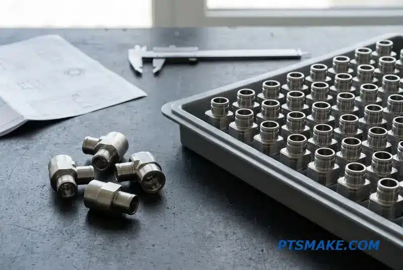
Sending a turning drawing to five shops and getting five wildly different quotes, lead times, and quality promises? You’re not alone. The real headache isn’t finding a CNC turning shop—it’s finding one that actually holds ±0.01mm without excuses or delays.
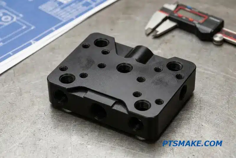
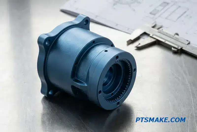
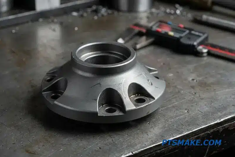
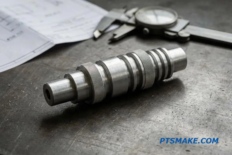
Precision CNC turning is a high-accuracy machining process that produces cylindrical parts with tight tolerances (typically IT6-IT7, or ±0.005-0.01mm), fine surface finishes (Ra 0.4-1.6 μm), and reliable geometric control on a rigid CNC lathe.
In this guide, I will walk you through a systematic framework for evaluating precision CNC turning suppliers. From tolerance capability to material choices, threading methods, and DFM communication—each section gives you the practical questions to ask before placing your next order.
Why Finding a Precision CNC Turning Partner Is Harder Than It Should Be
You send a drawing to five shops and get five wildly different quotes. This isn’t just about price; it’s about finding a partner who truly understands precision CNC turning. The real challenge is securing a supplier that consistently holds tight tolerances on complex parts.
The Real Search
Finding a shop is easy. Finding one that communicates effectively through design changes and delivers on time is not. It requires a partner who can manage the entire process, from material sourcing to final inspection, without friction. This ensures your project stays on track.
Local vs. Offshore Sourcing
Choosing between local and offshore suppliers presents its own set of trade-offs. Each has distinct advantages and disadvantages that can impact your project’s cost, timeline, and final quality.
| Factor | Local Sourcing | Offshore Sourcing |
|---|---|---|
| Cost | Generally Higher | More Competitive |
| Lead Time | Potentially Shorter | Often Longer |
| Communication | Simpler, same time zone | Can have gaps, delays |
| Quality | Easier to verify | Higher uncertainty |
This guide provides a framework to help you systematically evaluate and choose the right partner.
The variance in quotes isn’t arbitrary. It reflects deep differences in a shop’s capabilities, from their machinery to their quality control processes. A low quote might seem attractive, but it can hide significant risks that surface later in production, causing costly delays.
What Drives Quote Differences?
Understanding the factors behind pricing helps you assess a potential partner’s true value. A supplier’s investment in technology and process control directly impacts the quality and reliability of the final parts. This is where a partnership with a company like PTSMAKE becomes invaluable for complex projects.
Equipment and Tooling Choices
A shop using a high-end Swiss-type lathe will quote differently than one with a standard turning center. The former offers higher precision for complex parts but at a greater machine-hour rate. Tooling selection and process planning also play a crucial role in both cost and capability.
The Role of Quality Assurance
A significant cost driver is a supplier’s commitment to quality. Robust inspection processes, advanced Metrology1, and material traceability add to the upfront cost. However, they prevent expensive failures, recalls, and rework down the line, saving you money and protecting your brand’s reputation.
| Cost Factor | Low-Cost Quote Implication | Value-Oriented Quote Implication |
|---|---|---|
| Machine Time | Older, less precise machines | Advanced, high-precision equipment |
| Quality Control | Basic or no inspection | Rigorous, documented inspection |
| Tooling | General-purpose, worn tooling | Application-specific, new tooling |
| Expertise | Limited process planning | In-depth engineering support |
Finding a true precision CNC turning partner means looking beyond the initial quote. You must evaluate their technology, processes, and commitment to quality to ensure they can consistently meet your specifications and deliver reliable parts for your most critical applications.
Sourcing for precision CNC turning is challenging. The wide-ranging quotes you receive often reflect significant differences in equipment, quality control, and overall capability. A systematic approach is crucial to identifying a partner who can truly deliver on complex requirements and tight tolerances.
Precision CNC Turning Defined — What Engineers Actually Mean
When engineers specify "precision," we move beyond general terms. We are talking about quantifiable results. Precision CNC turning is defined by a set of measurable parameters that directly impact a part’s performance and assembly. It’s about achieving specific, verifiable metrics.
Key Technical Parameters
For us, precision means controlling roundness, typically between 0.005mm and 0.01mm on a high-quality CNC lathe. It also means achieving a specific surface finish, where Ra 0.4-1.6 μm is standard, and Ra 0.2 μm is possible with a final grinding pass.
Precision vs. Conventional Turning
The difference is not just about the final numbers. It is rooted in the process and equipment. Precision work requires machines with higher rigidity and more rigorous in-process inspection to ensure consistency.
| Feature | Conventional Turning | Precision Turning |
|---|---|---|
| Diameter Tolerance | IT8 – IT10 | IT6 – IT7 |
| Machine Rigidity | Standard | High |
| Inspection Level | Standard QC | Rigorous In-Process |
Precision CNC turning tolerances are not arbitrary; they are a function of the machine’s capability, tooling, and the operator’s skill. The process implies a commitment to holding tight control over every aspect of production, from material stability to thermal compensation in the machine tool.
Distinguishing from Swiss Turning
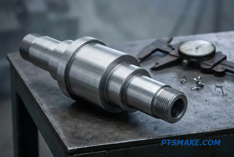
It’s also important to differentiate precision turning from Swiss turning. We use conventional precision turning for robust parts up to 300mm or more in length. Swiss turning, however, excels with very slender components where the length-to-diameter ratio is high, typically greater than 4:1.
| Method | Ideal Part Geometry | Max Diameter |
|---|---|---|
| Precision Turning | L:D < 4:1 | Up to 300mm+ |
| Swiss Turning | L:D > 4:1 | Typically < 38mm |
Process Control is Everything
Achieving these tight specifications, like a diameter tolerance of International Tolerance Grade2 IT6, requires more than just an advanced machine. At PTSMAKE, we’ve found that it demands a systematic approach, including strict environmental controls and advanced metrology to validate every dimension. This ensures components function reliably in critical applications.
Precision CNC turning is defined by tight, verifiable metrics like tolerance, roundness, and surface finish. It relies on superior machine rigidity and strict process controls, distinguishing it from both conventional turning and specialized Swiss-type machining for slender parts.
Tolerance Capability vs. Specification — When ±0.005mm Is Not a Lie
Have you ever received parts that failed inspection, even though the supplier promised a tight tolerance like ±0.005mm? It’s a common frustration. A machine’s specification sheet is not the same as its real-world production capability. This gap is where trust breaks down and projects get delayed.
The Promise vs. Reality
A manufacturer might advertise high precision, but delivering it consistently is another matter. Factors like tool wear, material variation, and temperature fluctuations can quickly derail production, turning a promise into a costly problem.
Key Factors in Tolerance
Understanding what truly affects precision is key. It’s not just the machine itself.
| Factor | Impact on Tolerance | Control Method |
|---|---|---|
| Machine Accuracy | Foundation for precision | Regular calibration |
| Process Control | Ensures consistency | Statistical Process Control (SPC) |
| Environment | Affects stability | Temperature and vibration control |
| Material Quality | Varies dimensions | Batch testing and certification |
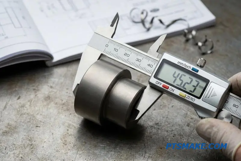
The trust gap often comes from confusing a machine’s positioning accuracy with its process capability. A high-end CNC turning lathe might have a positioning accuracy of ±0.0025mm, but this doesn’t mean it can hold that tolerance on every single part in a production run.
Machine Spec vs. Process Reality
True precision manufacturing relies on controlling variables. This is where the Process capability index3 (Cpk) becomes a more valuable metric than a simple tolerance claim. A high Cpk value indicates a stable, predictable process that stays well within the specification limits.
Environmental and Material Factors
In our shop, we manage variables that impact CNC turning tolerance capability. Coolant temperature control is critical to prevent thermal growth in the workpiece and machine components. Likewise, variations in raw material hardness can cause the tool to deflect differently, affecting final part diameters.
A Practical Rule for Procurement
Here’s a rule of thumb I use: if your drawing specifies a tolerance of ±0.01mm, you should partner with a supplier whose process capability for that feature is at least four times better, or ±0.0025mm. Don’t just ask if they can hold the tolerance; ask for their Cpk data on similar jobs.
True precision isn’t just a machine’s spec—it’s a controlled process. Ask potential suppliers for their Cpk values, not just tolerance claims, to verify their actual CNC turning tolerance capability and ensure you receive parts that consistently meet your specifications.
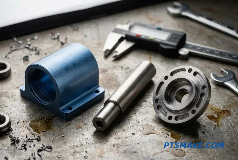
Materials That Make or Break Precision Turning Results
Selecting the right material is the first critical step in any Precision CNC Turning project. The material’s properties dictate not just the final part’s function but also the entire manufacturing strategy. It influences cutting speeds, tool selection, and ultimately, the achievable precision.
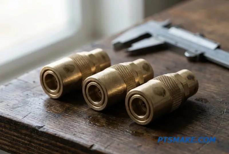
Free-Machining Metals
These materials are favorites for high-volume, high-precision work. Metals like 303 Stainless Steel, 12L14 Steel, and 360 Brass are designed for machinability. They produce small, manageable chips, leading to excellent surface finishes and allowing us to hold the tightest tolerances efficiently.
Why They Excel
Excellent chip breakage prevents long, stringy chips from wrapping around the part or tool. This stability is crucial for automated processes and maintaining consistent quality. At PTSMAKE, we often recommend these for parts requiring cosmetic perfection and dimensional accuracy.
Standard Precision Materials
Materials like 6061-T6 Aluminum and 304/316L Stainless Steel are versatile workhorses. While not as effortless to machine as free-machining grades, they offer a great balance of mechanical properties, corrosion resistance, and cost. Proper feed and speed adjustments are key to managing chip control.
Challenging Materials
This category is where expertise really shows. Materials like Inconel 718 exhibit extreme work hardening4, meaning the material gets harder as you cut it. This requires slow speeds, specialized tooling, and aggressive cooling to prevent tool failure. Titanium and hardened steels present similar challenges.
Plastics in Precision Turning
Plastics such as PEEK, PTFE, and Delrin are lightweight and corrosion-resistant but have high thermal expansion. Heat generated during cutting can cause dimensional instability. We use extremely sharp tools and specific cooling techniques to maintain accuracy.
Material Selection Guide
Here’s a simplified decision table based on our experience with materials for CNC precision turning. It helps align application needs with manufacturing realities.
| Application Example | Material | Turning Difficulty | Achievable Tolerance | Tooling Cost Multiplier |
|---|---|---|---|---|
| High-Volume Fasteners | 12L14 Steel | Low | ±0.01 mm | 1.0x |
| Electronic Enclosures | 6061-T6 Aluminum | Low-Medium | ±0.02 mm | 1.2x |
| Medical Implants | Titanium Grade 5 | High | ±0.025 mm | 3.5x |
| Aerospace Turbines | Inconel 718 | Very High | ±0.03 mm | 5.0x |
| High-Performance Seals | PEEK | Medium | ±0.05 mm | 1.8x |
Material choice is a balancing act between performance, machinability, and cost. The right selection upfront prevents downstream production headaches and ensures the final part meets every specification. At PTSMAKE, we guide clients through this process to ensure optimal results.
Surface Finish in Precision Turning — What Ra 0.4 vs 1.6 Actually Costs
In precision CNC turning, the specified surface finish directly impacts the final cost. A common question I get is about the real difference between an Ra 1.6 μm and an Ra 0.4 μm finish. While both seem smooth, the journey to achieve the finer finish involves significant changes in the machining process.
The Time and Cost Connection
Achieving a tighter surface finish like Ra 0.4 μm requires a much lower feed rate. This directly extends the machine’s cycle time for each part. More machine time means higher operational costs, which are then passed on to the final price of the component.
A Practical Rule of Thumb
Based on studies with our customers, moving from a standard Ra 1.6 μm to a fine Ra 0.4 μm finish can often double the turning cycle time. This seemingly small change on a drawing can have a substantial effect on the budget, especially for production runs.
Understanding the cost drivers behind surface finish is crucial for effective design for manufacturability. The primary relationship is simple: a finer finish demands slower tool movement across the part’s surface, which increases the time needed to complete the machining operation.
Roughing vs. Finishing Strategies
A common strategy in precision CNC turning is to use a two-step process. First, a roughing pass quickly removes most of the material. Then, a finishing pass with a small depth of cut (typically 0.1-0.3mm) and a low feed rate achieves the desired surface quality. This is where the cost accumulates.
| Parameter | Ra 1.6 µm (Standard Finish) | Ra 0.4 µm (Fine Finish) |
|---|---|---|
| Typical Feed Rate | Higher | Significantly Lower |
| Cycle Time Index | 1.0x | ~2.0x |
| Tooling Choice | Standard Inserts | Wiper or CBN Inserts |
| Secondary Ops | Often None | May Require Roller burnishing5 |
Advanced Finishing Techniques
To optimize this process, we sometimes use wiper insert technology. These inserts allow for a higher feed rate while maintaining a fine finish, effectively reducing cycle time. For hardened materials, CBN inserts are essential. In some cases, a secondary operation is the only way to meet extremely tight specifications.
It is critical to avoid over-specifying. If an Ra 0.8 μm finish is functionally sufficient for your application, specifying Ra 0.2 μm will needlessly inflate production costs and lead times. Always match the specification to the actual functional requirement.
Specifying a finer surface finish than necessary is a common source of avoidable cost. Moving from Ra 1.6 to Ra 0.4 can double cycle time, so ensure the engineering requirement justifies the increased expense.
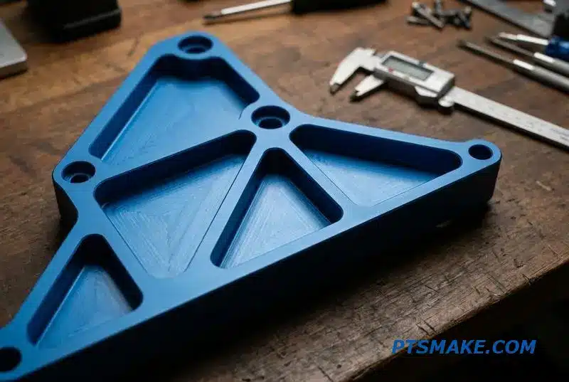
Geometric Tolerances — Which Ones Really Matter in Precision Turning
In precision CNC turning, not all geometric tolerances are created equal. Some are inherent to a well-maintained machine, while others drive significant cost. Understanding the difference is crucial for designing parts that are both functional and manufacturable within a reasonable budget.
Key Achievable Tolerances
We consistently achieve tight control over certain features. Roundness and perpendicularity, for example, are relatively simple to manage with the right setup. The real challenge, and cost, often comes from controlling relationships between features, especially across multiple operations.
Balancing Precision and Cost
The key is to focus on what matters for your assembly. Over-specifying a tolerance that the turning process naturally controls only adds to inspection time and expense. Below is a quick guide based on our experience at PTSMAKE.
| Tolerance | Standard Achievable Value | Notes on Cost & Complexity |
|---|---|---|
| Roundness | 0.005mm | Low cost with proper chucking and machine balance. |
| Concentricity | 0.01mm (Single Setup) | Cost increases with re-chucking or sub-spindle transfers. |
| Cylindricity | Varies (Length Dependent) | Challenging and costly on parts over 10x diameter. |
| Perpendicularity | 0.005mm per 10mm Radius | Relatively straightforward to control on faces. |
The method used to hold the workpiece is one of the biggest factors influencing CNC turning geometric tolerances. It’s a detail that can make or break the precision of your final part. Thinking about it early in the design phase can save a lot of trouble later.
How Workholding Dictates Results
A standard three-jaw chuck with hard jaws is quick for setups but can introduce run-out and distort thin-walled components. For high-precision work, we almost always turn custom soft jaws. This ensures the part is clamped with minimal distortion and runs true to the machine’s centerline.
Collets vs. Jaw Chucks
Collet chucks are excellent for smaller diameter bar-fed production, providing 360-degree contact for superior concentricity. Hydraulic chucks also improve consistency over manual ones by applying the same clamping force every time, which is critical for stable production runs.
The Hidden Cost of Redundant Callouts
A frequent issue I see on drawings is specifying a tight concentricity between two diameters turned in the same setup. The machine’s spindle accuracy inherently controls this relationship. Adding the callout doesn’t make the part better; it just adds inspection cost. The real concern for error is Datum shift6 when a part is moved to a sub-spindle or a second operation.
To optimize for precision CNC turning, focus your tightest tolerances on features critical to function. Understanding how workholding and machine setups impact geometry allows for smarter design choices, ensuring performance without driving up manufacturing costs unnecessarily.
The Hidden Cost of Secondary Operations in Precision Turning
In precision turning, the most significant expenses often occur after the part is removed from the lathe. These secondary operations add steps, time, and complexity, directly impacting your final unit cost. Each additional setup introduces new variables and potential for error.
The True Cost Drivers
Operations like cross-drilling, grinding, and heat treatment are common requirements. While necessary, they inflate costs and extend lead times. Understanding these steps is crucial for accurate project quoting and planning, as they can sometimes double the initial turning cost.
Common Secondary Operations & Cost Impact
| Operation | Typical Cost Impact | Primary Challenge |
|---|---|---|
| Cross-Drilling/Milling | Adds milling setup cost | Requires re-fixturing |
| Heat Treatment | +$0.50 to $5 per part | Batch process, adds lead time |
| Centerless Grinding | Can be 2-3x turning cost | Tight tolerance control |
| Keyway Broaching | Adds setup + tooling cost | Specialized equipment needed |
The debate between a conventional lathe plus secondary operations versus a single-setup turn-mill machine comes down to total cost and risk management. The true cost of CNC turning secondary operations is not just the labor for each step; it includes handling, re-fixturing, and quality control.
Single-Setup vs. Multi-Setup: A Cost Comparison
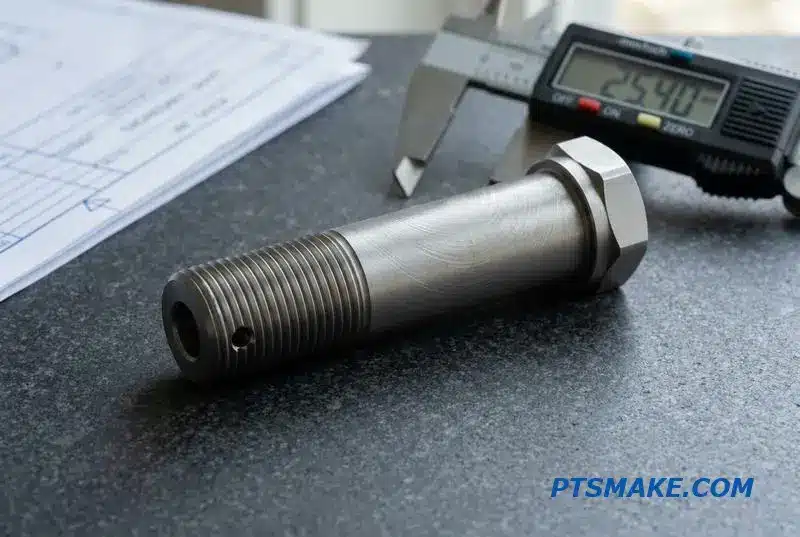
Consider a typical aerospace threaded shaft requiring a cross-hole and a hex feature. On a conventional lathe, this part needs at least three separate setups after the initial turning. Each time the part is moved and re-clamped, you risk losing accuracy.
This is where the risk to Concentricity7 becomes a major factor. Every new setup introduces a potential for misalignment between features that should share a common axis. It adds inspection time and increases the scrap rate, which is a significant hidden cost.
With our advanced turn-mill centers at PTSMAKE, we complete all these features in one continuous cycle. This approach eliminates re-fixturing errors, reduces labor, and shortens the overall production time significantly.
Cost Breakdown: Conventional vs. Turn-Mill
| Cost Factor | Conventional Lathe + 3 Setups | Single-Setup Turn-Mill |
|---|---|---|
| Machining Time | Base Turning Cost | +25% Cycle Time |
| Setup & Handling | +150% (3 extra setups) | Included |
| Quality Risk | High (Datum shifts) | Low (Single datum) |
| Total Cost Index | ~1.7x Base Cost | ~1.2x Base Cost |
Secondary operations add significant cost, lead time, and quality risks. An integrated turn-mill approach minimizes these factors, providing a more reliable and cost-effective solution for complex components by reducing the overall cost of CNC turning secondary operations.
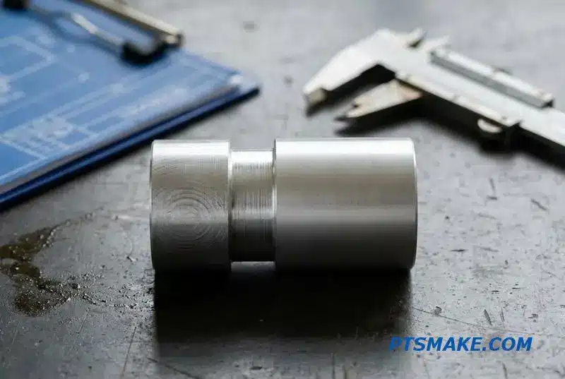
Heat Treat and Precision Turning — The Order of Operations Trap
Getting the sequence wrong between heat treatment and precision CNC turning is a costly trap. A part can be perfectly machined, only to be ruined by distortion after hardening. The correct order is crucial for maintaining tight tolerances on hardened components.
The Standard, Correct Sequence
For alloy steels requiring hardness like 30-45 HRC, the process must be staged. We first rough turn the part, leaving a specific amount of extra material. Only after heat treatment do we perform the final, precise turning operation to achieve the final dimensions.
Why Order Matters
Heat treatment is not a gentle process. It causes the material to move and distort. If you finish the part to its final size before this step, those critical dimensions will be lost. The part will almost certainly be out of tolerance.
| Incorrect Sequence | Correct Sequence |
|---|---|
| 1. Finish Turn | 1. Rough Turn (leave 0.3-0.5mm stock) |
| 2. Heat Treat | 2. Heat Treat to Specification |
| 3. Part is distorted | 3. Finish Turn to Final Dimension |
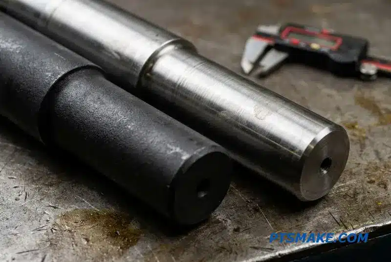
The core issue is that heat treatment fundamentally alters the steel’s internal structure, causing dimensional changes. These changes are unavoidable. This is why we leave 0.3-0.5mm of stock material on the part during the initial roughing stage.
Managing Post-Treatment Effects
This extra material serves as a buffer. It absorbs the effects of distortion, scaling, and decarburization8, which is a loss of carbon from the surface layer. After the part is hardened and stabilized, we mount it again for finish turning, removing that stock to reveal a perfectly dimensioned, hard surface.
A Real-World Failure
I recall a project with a 4140 steel shaft. The client’s initial drawing didn’t specify the manufacturing sequence. A less experienced shop turned it to the final dimension first, then sent it for heat treatment. The result? The shaft was 0.05mm out of round, completely useless.
Hard Turning: An Advanced Method
For parts needing hardness above 45 HRC, we often use a technique called hard turning. This still follows the same sequence—heat treat first, then finish machine. It requires extremely rigid CNC lathes and specialized CBN (Cubic Boron Nitride) inserts to cut the hardened steel, eliminating the need for grinding. At PTSMAKE, we leverage this for high-precision components.
| Method | Best For | Key Requirement |
|---|---|---|
| Finish Turning | Hardness < 45 HRC | Standard Carbide Tooling |
| Hard Turning | Hardness > 45 HRC | Rigid Machine, CBN Tooling |
For successful outcomes in heat treat and CNC turning sequence, always specify the correct order in your RFQ. This simple step prevents scrap, delays, and budget overruns by ensuring the part is finished after it has achieved its final material properties.
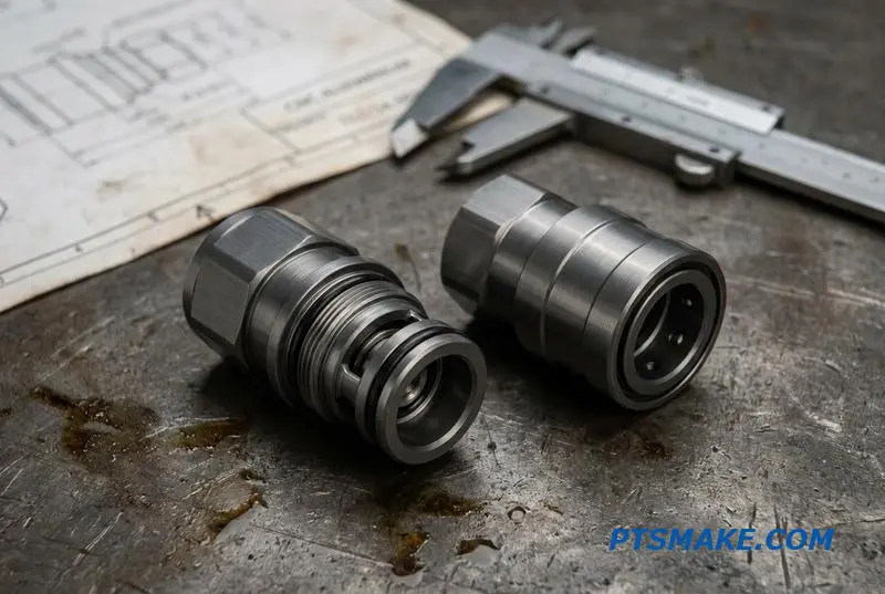
Threading in Precision Turning — Single-Point vs. Thread Rolling
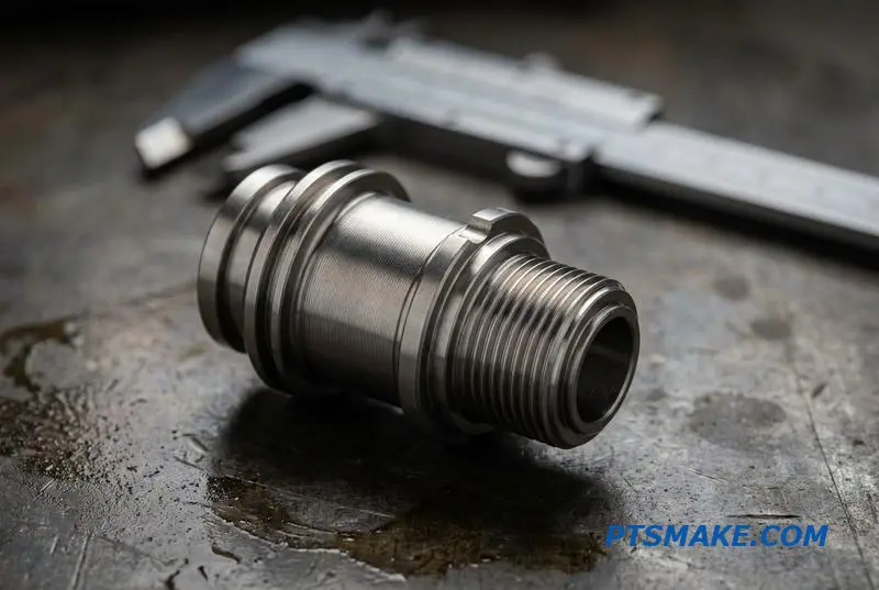
When creating threads on turned parts, the choice between single-point threading and thread rolling is critical. Each method has distinct advantages. Single-point threading cuts the material, offering great flexibility for prototypes and custom pitches. It’s a go-to for low-volume production where tooling costs must be minimized.
Single-Point Threading
This method uses a single-point tool to cut the thread groove. It is performed directly on the CNC lathe, making it highly versatile. It’s ideal for projects with non-standard thread profiles or when a quick turnaround is necessary without investing in dedicated tooling for the job.
Thread Rolling
Thread rolling is a cold-forming process. It displaces material to form the threads instead of cutting it away. This results in superior strength and a better surface finish. It’s often a secondary operation but delivers threads that can withstand high-vibration environments effectively.
| Feature | Single-Point Threading | Thread Rolling |
|---|---|---|
| Process | Material Cutting | Material Forming |
| Strength | Standard | 20-30% Stronger |
| Best For | Prototypes, Low Volume | High Volume, Critical Parts |
| Tooling Cost | Low | High |
| Lead Time | Short | Longer (Tooling) |
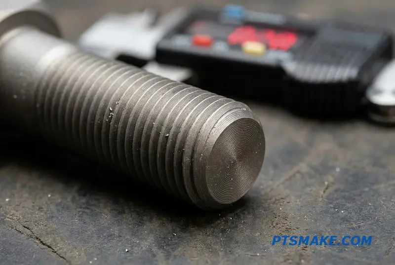
The primary difference lies in how the material’s structure is altered. Single-point cutting severs the material’s grain, creating potential stress points. Thread rolling, however, reshapes the material. This cold-forming process improves the Material grain flow9, which follows the contour of the thread. This is why it yields significantly higher fatigue strength.
Specifying Threads Correctly
For any precision CNC turning project, clear specifications are vital. When calling out threads on a drawing, be sure to define the thread class. Class 2A/2B offers a standard fit for general use, while Class 3A/3B provides a tighter tolerance for applications where precision is paramount. The choice impacts both performance and cost.
| Thread Class | Fit Tolerance | Common Application |
|---|---|---|
| 2A/2B | Standard | General purpose fasteners, commercial products |
| 3A/3B | Tight | Aerospace, high-performance machinery |
Also, specify the required thread runout and chamfer. A chamfer is crucial for easy assembly and preventing cross-threading. Specifying runout ensures the thread axis is properly aligned with the part’s datum features, which is critical for high-speed rotating components. These details prevent assembly issues downstream. Proper precision turning thread rolling specifications are key.
Choosing between single-point and rolled threads depends on your application’s demands. Single-point threading offers flexibility for prototyping, while thread rolling provides superior strength for critical, high-volume parts in industries like aerospace and automotive. Clear drawing specifications are essential for both.
Run Quantity Strategy — How Volume Changes Your Precision Turning Approach
The number of parts you need completely changes the manufacturing game. A strategy that works for ten prototypes will be incredibly inefficient for a thousand-piece run. Your precision turning production volume strategy must adapt to balance setup costs against per-part cycle time.
Understanding the Volume Zones
For prototypes, speed is everything. We prioritize fast setup, often using manual programming. As volume increases, the focus shifts to optimizing every second of the cycle time. Full automation only makes sense for very high quantities where initial investment pays off.
Cost Drivers by Volume
| Production Volume | Primary Cost Driver | Typical Approach |
|---|---|---|
| Prototype (1-50) | Setup & Engineering Time | Manual Programming |
| Low-Volume (50-500) | Blended Setup & Cycle Time | CAM Optimization |
| Mid-Volume (500-5,000) | Cycle Time & Tool Life | Process Monitoring |
| High-Volume (5,000+) | Automation & Material Cost | Dedicated Machinery |
This framework helps align the manufacturing approach with the project’s economic realities.
Scaling production isn’t just about running the machine longer; it’s a fundamental shift in process engineering. Each volume zone has an inflection point where a different approach becomes more cost-effective. At PTSMAKE, we guide clients through these transitions to ensure efficiency.
Low to Mid-Volume Transition
Moving from low to mid-volume (around 500 pieces) is where automation starts paying dividends. We implement fully optimized bar feeders and use CAM simulation to shave seconds off the cycle. We also introduce Statistical Process Control (SPC) and tool life monitoring to maintain consistency without inspecting every single part.
High-Volume Optimization
For high-volume runs exceeding 5,000 parts, the economics justify dedicated machinery like multi-spindle automatic lathes. These machines reduce cycle time dramatically. The goal becomes "lights-out" production, where automation handles material loading, part unloading, and in-process gauging with minimal human intervention. Aligning this with customer demand requires understanding Takt time10.
| Strategy | Low-Volume (50-500) | Mid-Volume (500-5,000) | High-Volume (5,000+) |
|---|---|---|---|
| Programming | CAM Programmed | CAM with Simulation | Highly Optimized |
| Material Feed | Bar Feeder (If Possible) | Fully Optimized Bar Feed | Automated Loading |
| Inspection | Sample Plan (F/L/M) | SPC Sampling | In-Process Gauging |
| Tooling | Standard Tooling | Tool Life Monitoring | Optimized for Speed |
Choosing the right strategy is crucial for a successful outcome in precision CNC turning.
Choosing the right precision turning production volume strategy is essential. It balances initial setup costs with per-part efficiency, ensuring your project is cost-effective at any scale. The key is adapting the process to match the quantity, from single prototypes to mass production.
Deburring and Edge Finish — The Step Everyone Underestimates
In precision CNC turning, deburring is far more than simple cleanup. It’s a critical step that directly impacts part performance, safety, and assembly. Overlooking it leads to functional failures and unexpected costs. A sharp edge can cut wires, disrupt fluid dynamics, or prevent proper mating.
Understanding Burr Formation
Burrs are unwanted raised edges of material that remain after machining. The type of burr depends heavily on the toolpath and material properties. Understanding their origin is the first step to effective removal.
| Burr Type | Cause | Common Location |
|---|---|---|
| Exit Burr | Tool pushes material out as it exits a cut. | Cross-drilled holes, intersecting features. |
| Roll-over Burr | Material is pushed over an edge during cutoff. | Parting line on turned components. |
| Poisson Burr | Lateral material flow from heavy cutting pressure. | Side of a deep groove or heavy cut. |
Proper edge finishing isn’t just about aesthetics; it is a functional requirement. The choice of deburring method directly influences both the final part quality and the overall project budget. A mismatch between the method and the requirement can lead to inconsistent results or unnecessary expenses.
Selecting the Right CNC Turning Deburring Methods
Different methods offer trade-offs between cost, consistency, and suitability for complex geometries. For instance, manual deburring is flexible but relies heavily on operator skill. It’s often inconsistent for high-volume jobs, where automated processes deliver superior repeatability. This is where plastic deformation11 comes into play, as burrs are a direct result of it.
| Deburring Method | Best For | Consistency | Relative Cost |
|---|---|---|---|
| Manual | Low-volume, simple geometries | Low | Low |
| Tumbling | Bulk parts (500+), non-critical edges | Medium | Medium |
| Thermal | Internal, hard-to-reach intersections | High | High |
| Robotic | High-volume, high-precision parts | Very High | Very High |
| Water Jet / Blasting | Delicate features, specific surfaces | High | High |
Clear Drawing Specifications
To avoid ambiguity, drawings must clearly define edge requirements. Vague notes like "Deburr all edges" are problematic. Instead, specify an edge break, such as a "0.1-0.3mm × 45° chamfer" or a "R0.2 max radius." This ensures everyone, from machinist to inspector, understands the exact requirement.
Deburring is a crucial manufacturing step, not a cosmetic afterthought. Selecting the appropriate method and clearly defining edge specifications on drawings are essential for managing costs and ensuring the functional integrity of precision turned parts. It bridges design intent with final production quality.
Communication and DFM — What Sets Great Precision Turning Partners Apart
Beyond technical skill, the true value of a precision turning partner lies in communication. A great supplier doesn’t just execute a program. They actively engage with your design, bringing manufacturing expertise to the table to enhance it. This collaborative approach is key to success.
From RFQ to Partnership
The initial request for quotation (RFQ) sets the tone. A partner will review your drawings and proactively offer suggestions. This dialogue transforms a simple transaction into a partnership focused on optimization, ensuring the final part is both functional and cost-effective to produce.
DFM Suggestion Examples
| Suggestion Type | Example | Impact |
|---|---|---|
| Tooling Optimization | Increase an internal corner radius from R0.2 to R0.5. | Eliminates a special insert, reducing cost by 8%. |
| Process Improvement | Note that two features will be machined in the same clamping. | Allows for a tighter concentricity callout at no extra cost. |
| Material Choice | Suggest an alternative alloy with similar properties. | Improves machinability and lowers material expense. |
This proactive feedback is the hallmark of an expert partner dedicated to your project’s success. It demonstrates a deeper level of engagement beyond simply quoting a price.
A partner’s communication style becomes clear during the RFQ process. What matters is not just getting a quote, but getting actionable feedback. At PTSMAKE, we have refined this process to ensure clarity and efficiency from the very beginning.
The Ideal RFQ Workflow
The best partnerships start with a well-defined process. Sending a 3D STEP file and a 2D PDF with critical dimensions highlighted is the ideal first step. This provides all the necessary information for a thorough initial review.
Our Response Timeline
| Step | Action | Timeline |
|---|---|---|
| 1 | You send 3D + 2D files with critical callouts. | N/A |
| 2 | We respond with feasibility and a preliminary quote. | Within 24 hours |
| 3 | We schedule a CNC turning DFM review call. | 1-2 business days |
| 4 | Program, FAI, and production begin. | Per agreed timeline |
Red Flags to Watch For
A supplier that accepts a drawing without questions is a major red flag. They may not have reviewed the details, leading to problems later. Equally concerning is a supplier that asks no clarifying questions about your Geometric Dimensioning and Tolerancing12. This indicates a lack of deep understanding.
Exceptional precision turning partners don’t just make parts; they improve them. Proactive communication and a rigorous CNC turning DFM process are the true differentiators, transforming a supplier relationship into a powerful manufacturing partnership that delivers value beyond the machine.

Discover how the science of measurement ensures your parts meet exact specifications and functional requirements. ↩
Explore how IT grades define manufacturing process capabilities and affect component costs. ↩
This metric quantifies how well a process can produce output within specified limits. ↩
Understanding this phenomenon is key to successfully machining high-performance alloys and avoiding costly tool failures. ↩
Discover how this chipless process achieves mirror-like finishes and improves surface hardness without material removal. ↩
Understanding this concept helps prevent error accumulation in multi-operation turning processes. ↩
Understanding this geometric tolerance is key to evaluating quality risks in multi-setup manufacturing. ↩
Understand how this surface carbon loss impacts material hardness and machinability after heat treatment. ↩
Understanding this helps predict a component’s fatigue life and mechanical strength. ↩
Understanding this helps align production speed with demand, crucial for optimizing inventory and workflow efficiency. ↩
Explore how this material behavior influences burr size and shape during machining operations. ↩
Explore how this symbolic language ensures your design intent is perfectly translated into a physical part. ↩