You’re designing a high-performance electronic system, but traditional air cooling can’t handle the intense heat your components generate. Your project demands precise thermal management, yet conventional solutions leave you facing overheating, performance throttling, and potential system failures.
A liquid cooling plate is a specialized heat exchanger that uses circulating coolant to efficiently remove heat from high-power electronic components, offering superior thermal performance compared to air cooling by directly conducting heat away through engineered internal flow channels.
The success of your cooling solution depends on understanding the engineering principles behind these systems and selecting the right design for your specific application. Let me walk you through the essential knowledge that will help you make informed decisions about liquid cooling plate design and manufacturing.
What core problem does a liquid cooling plate solve?
Simply put, a liquid cooling plate tackles heat. But not just any heat. It solves the problem of highly concentrated heat that simpler solutions, like fans, cannot handle.
Think of it this way. Your device is getting smaller, yet more powerful. This creates intense hotspots. Air cooling eventually reaches its limit and can’t remove heat fast enough.
When Air Cooling Hits Its Limit
This is where a liquid cooling plate becomes essential. It provides a direct and efficient path to move thermal energy away from critical components.
| Cooling Method | Heat Removal Capacity | Ideal Application |
|---|---|---|
| Air Cooling | Low to Moderate | General Electronics |
| Liquid Cooling | High to Very High | High-Power Processors, Lasers |
A liquid cooling plate is not an upgrade; it is a necessary solution for modern high-power electronics. It ensures reliability and performance.
The core issue is a mismatch. The rate of heat generation in a tiny area outpaces the rate at which air can physically absorb and carry it away. This challenge is defined by two key concepts.
The Challenge of High Power Density
Power density refers to the amount of power packed into a given volume. As devices shrink, power density skyrockets. This leads to a rapid temperature increase that can cause performance throttling or even permanent damage to components.
Understanding Heat Flux
Heat flux is the rate of heat energy transfer through a surface. In high-performance chips, this value can be incredibly high. Air’s low thermal conductivity acts as a bottleneck, creating significant thermal resistance1.
In past projects at PTSMAKE, we have seen that switching to a liquid cooling plate can reduce component temperatures by a significant margin compared to the most robust air-cooling setups. Coolant is simply more effective at absorbing and transporting heat.
| Medium | Thermal Conductivity (W/m·K) |
|---|---|
| Air | ~0.026 |
| Water | ~0.6 |
| Ethylene Glycol/Water (50/50) | ~0.4 |
This table shows a stark difference. Water is over 20 times more conductive than air. This fundamental property is why liquid cooling is the superior solution for intense thermal loads.
A liquid cooling plate directly addresses the physical limits of air cooling. It becomes indispensable when dealing with high power density and heat flux, ensuring your device remains stable, reliable, and performs as designed.
What are its fundamental components and their functions?
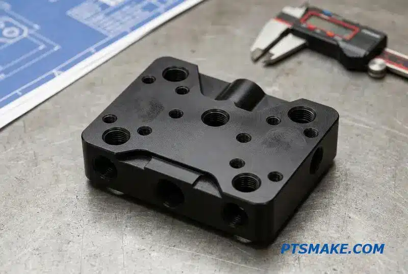
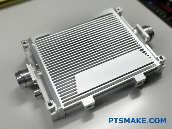
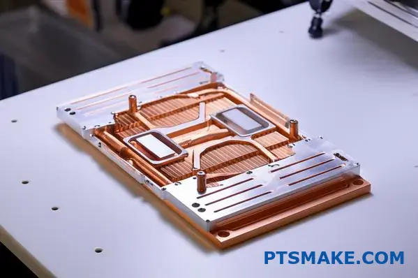
A liquid cooling plate might seem complex. But it’s really made of four essential parts. Each one has a specific job. Together, they create an efficient heat removal system.
The base is the foundation. It directly touches the heat source. Then, internal channels guide the cooling fluid. Inlet and outlet ports connect the plate to the larger system. Finally, a cover seals everything, preventing any leaks.
| Component | Primary Function |
|---|---|
| Base Plate | Absorbs heat directly from the component. |
| Internal Channels | Creates a path for the coolant to flow. |
| Inlet/Outlet Ports | Connects the plate to the cooling loop. |
| Cover | Seals the internal channel system. |
The Critical Role of Each Component
Let’s break down how these parts work together. The design of each component is crucial for the performance of the entire liquid cooling plate. Small details make a big difference.
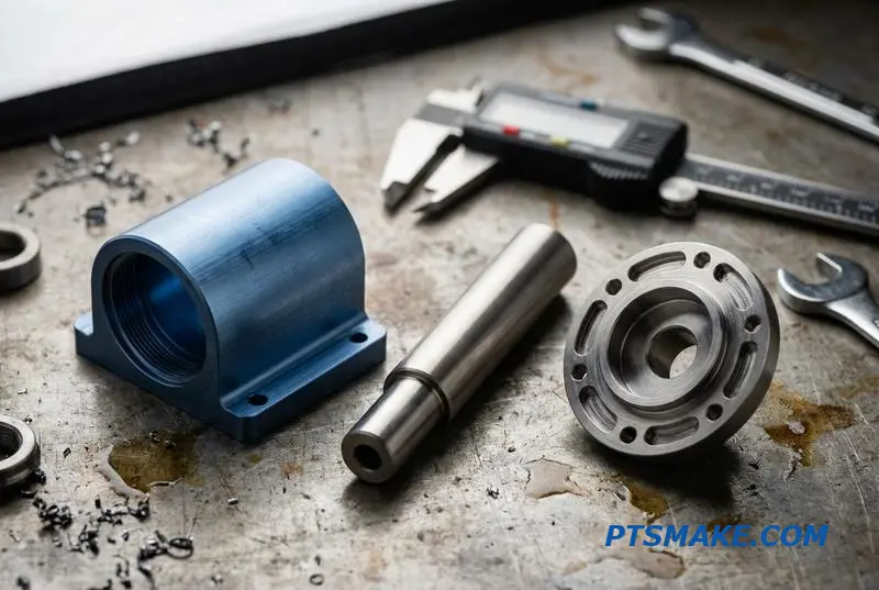
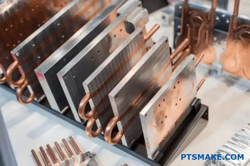
Base Plate and Material Choice
The base plate’s main job is absorbing heat. Its material is key. In past projects at PTSMAKE, we’ve found copper and aluminum to be the most common choices. Their properties suit different needs.
| Material | Thermal Conductivity | Key Benefit |
|---|---|---|
| Copper | High | Maximum heat transfer. |
| Aluminum | Good | Lightweight and cost-effective. |
The choice depends on the application’s budget and thermal requirements. A perfectly flat surface is also vital for optimal contact.
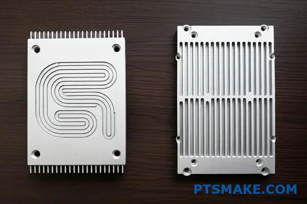
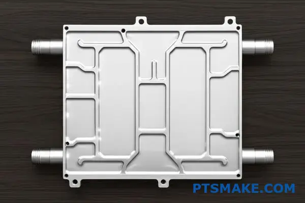
Internal Channels and Flow Dynamics
Inside the plate, the channels dictate the coolant’s path. The goal is to maximize the surface area the fluid touches. This design encourages turbulent flow2, which is much better at picking up heat than smooth, laminar flow. Channel patterns can be simple or highly complex.
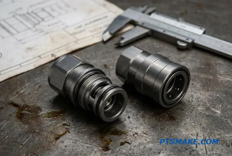
Ports and Cover Integrity
The inlet and outlet ports are the gateways. They must provide a secure, leak-proof connection to the rest of the cooling system. The cover plate seals the channels from above. It ensures the pressurized coolant stays inside, doing its job without any issues.
Every part of a liquid cooling plate, from the base to the channels and cover, must work in harmony. The selection of materials and the precision of the design directly impact its ability to manage heat effectively and reliably.
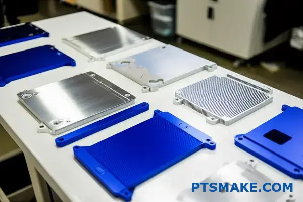
How are cold plates classified by manufacturing process?
Choosing the right manufacturing process is crucial. It directly impacts your liquid cooling plate’s performance and cost. Each method offers a unique balance of thermal efficiency and production scalability.
Let’s break down the common types.
Primary Manufacturing Methods
| Method | Key Advantage | Best For |
|---|---|---|
| Brazing | High Performance | Complex internal fin geometries |
| FSW | High Reliability | Large, robust aluminum plates |
| Machining | High Precision | Prototypes, complex external features |
| Die Casting | High Volume | Mass production with lower costs |
This overview helps frame the decision-making process.
Understanding the pros and cons of each process is key. At PTSMAKE, we guide clients through these options to match their specific application and budget. Let’s look closer at the details.
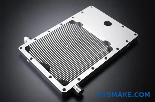
Brazed Cold Plates
Brazing involves joining components using a filler metal. This allows for complex internal structures, like high-density fins. The result is excellent thermal performance. However, the process is complex and can be costly. Ensuring a complete, void-free joint is critical.
Friction Stir Welded (FSW) Plates
FSW is a solid-state joining process. It creates a very strong, leak-proof bond without melting the base material. This method produces an incredibly reliable hermetic seal3. It is ideal for large aluminum plates, though tooling costs can be high for initial setup.
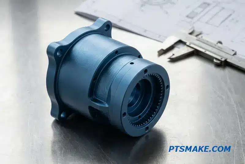
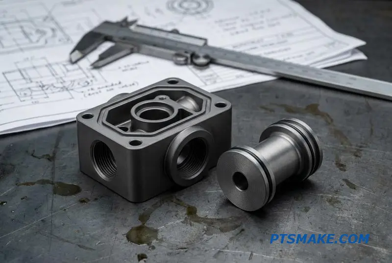
Machined & Gun-Drilled Plates
For prototypes or low-volume runs, we often recommend machining. Gun drilling creates long, straight cooling channels directly into a solid metal block. It offers great design flexibility and precision. The main drawback is that it’s slower and more expensive for high-volume production.
Die-Cast Cold Plates
When you need thousands of identical parts, die casting is the answer. It involves injecting molten metal into a mold. This process is fast and cost-effective at scale. The trade-off is lower thermal performance compared to brazed or FSW plates.
| Manufacturing Process | Pros | Cons |
|---|---|---|
| Brazing | Excellent thermal performance, complex internal geometries. | Higher cost, complex process control. |
| FSW | High reliability, strong leak-proof joints. | Higher initial tooling costs, limited to simpler channels. |
| Machined | High precision, ideal for prototypes, design flexibility. | Slower production, higher cost per unit in volume. |
| Die Casting | Low cost at high volume, fast production cycles. | Lower thermal performance, high initial mold cost. |
Each manufacturing method presents a distinct set of trade-offs. The optimal choice depends on thermal requirements, production volume, material compatibility, and overall project budget. We help clients navigate these factors to find the perfect fit.
The manufacturing process defines a cold plate’s core attributes. Your choice impacts everything from thermal efficiency to unit cost, dictating its suitability for prototyping, high-performance computing, or mass-market electronics. Careful selection is essential for project success.
What are the main types of internal flow paths?
Choosing the right internal flow path is key. It directly impacts your liquid cooling plate’s performance. The design dictates how coolant moves and absorbs heat.
We will explore three common layouts. Each has unique strengths and weaknesses. Understanding them helps you make better design choices.
Key Channel Layouts
Let’s compare the main types.
| Design Type | Key Feature | Best For |
|---|---|---|
| Serpentine | Single, continuous path | Targeted hot spot cooling |
| Parallel | Multiple parallel channels | Uniform, low-pressure cooling |
| Microchannel | Extremely small channels | Maximum heat transfer |
This choice affects thermal efficiency and pressure drop. It is a critical engineering decision.
The ideal channel layout balances competing factors. There is no single "best" solution for every project. It’s about finding the right trade-offs for your specific application.
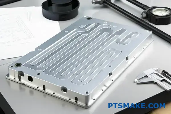
Serpentine Flow Path
A serpentine path forces coolant through one long, winding channel. This keeps the fluid velocity high. It ensures excellent heat transfer along the path. However, this creates a significant pressure drop, requiring a more powerful pump.
Parallel Flow Path
Parallel designs split the flow into multiple channels. These channels then merge back together. This approach dramatically reduces the overall pressure drop. The main challenge is ensuring uniform flow distribution across all channels to avoid stagnant zones.
Microchannel Design
Microchannels maximize the surface area for heat exchange. This results in superior thermal performance. The flow regime, often characterized by the Reynolds number4, is critical here. At PTSMAKE, we use precision CNC machining to create these complex structures. They are, however, more susceptible to clogging and have a very high pressure drop.
| Layout | Pressure Drop | Thermal Performance | Key Consideration |
|---|---|---|---|
| Serpentine | High | Good to Excellent | Pump power |
| Parallel | Low | Good | Flow distribution |
| Microchannel | Very High | Excellent | Clogging risk & cost |
Each internal flow path—serpentine, parallel, and microchannel—presents a distinct trade-off between thermal efficiency and pressure drop. The optimal choice for your liquid cooling plate depends entirely on your application’s specific cooling requirements and system constraints.
When would you choose a serpentine over a parallel design?
Choosing between a serpentine and a parallel flow path is a critical decision. It directly impacts your liquid cooling plate’s performance. It’s not about which is better overall. It’s about which is right for your specific application.
This simple framework helps you decide. We’ll look at three key factors: temperature goals, pressure limits, and your heat source’s shape.
| Design Attribute | Serpentine Design | Parallel Design |
|---|---|---|
| Flow Path | Single, long channel | Multiple, shorter channels |
| Pressure Drop | Higher | Lower |
| Temp. Uniformity | Lower | Higher |
Let’s break down how to use these criteria.
Deciding on the best design requires balancing competing requirements. In past projects at PTSMAKE, we’ve helped clients navigate these trade-offs to achieve optimal thermal management.
Temperature Uniformity: Your Top Priority?
If your component requires a very stable and uniform temperature across its surface, a parallel design is almost always the better choice. Coolant is distributed evenly, minimizing temperature gradients.
A serpentine path, by contrast, heats the fluid as it travels. This creates a noticeable temperature difference from the inlet to the outlet, which can be a problem for sensitive electronics.
Allowable Pressure Drop
Pressure drop dictates your pump requirements. A long serpentine path creates significant resistance, requiring a more powerful—and often more expensive—pump to maintain the necessary volumetric flow rate5.
A parallel design splits the flow, drastically reducing the pressure drop. This allows for smaller pumps, saving cost and energy.
Heat Source Geometry
The shape and concentration of your heat source matter.
| Heat Source Type | Recommended Design | Why It Works Best |
|---|---|---|
| Large, Uniform Area | Parallel | Ensures even cooling across the entire surface. |
| Small, Concentrated | Serpentine | Directs the entire cool fluid flow over the "hot spot". |
| Irregular Shape | Hybrid/Custom | Can be tailored to match complex thermal loads. |
Considering these factors ensures your liquid cooling plate design is effective from the start.
Choosing the right flow path for your liquid cooling plate involves a trade-off. Your decision should balance desired temperature uniformity against allowable pressure drop and the specific geometry of your heat source. This framework provides a clear path to the most effective solution.
What is the structure of a complete liquid cooling loop?
A liquid cooling loop is more than just a single part. It’s a complete system. Each component has a specific job.
The liquid cooling plate is crucial. But it cannot work alone. It needs support from other parts to function correctly.
The Core Components
Let’s look at the key players in this system. They all work together to move heat away from your critical electronics.
| Component | Primary Function |
|---|---|
| Pump | Circulates the coolant |
| Radiator | Dissipates heat into the air |
| Reservoir | Holds extra coolant |
| Tubing | Connects all components |
Understanding this structure is the first step. It helps in designing an effective thermal management solution.
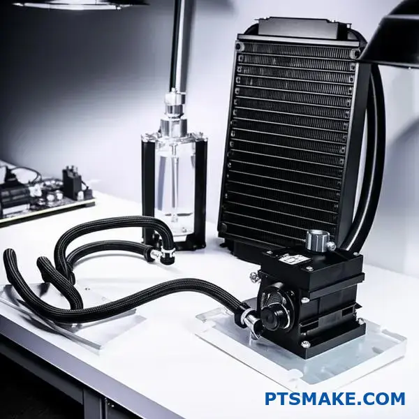
A liquid cooling plate is where the magic starts. It directly absorbs heat from the source, like a CPU or power electronics. But what happens to that heat? It enters the coolant. This is where the rest of the loop takes over.
The Journey of Heat
The pump is the engine of the system. It pushes the heated coolant away from the plate. The coolant then travels through tubing to the radiator.
A radiator, or heat exchanger, has a large surface area. Fans often blow air across it. This process transfers heat from the coolant to the surrounding air. The now-cooled liquid continues its journey.
The final stops are the reservoir and back to the pump. The reservoir ensures there’s always enough fluid. It also helps remove air bubbles from the loop. This entire cycle is a continuous flow.
The efficiency of this cycle depends on many factors. The rate of heat flux6 at the cold plate is critical. So is the pump’s flow rate and the radiator’s dissipation capacity.
At PTSMAKE, we focus on how our CNC machined components integrate. A well-designed liquid cooling plate must match the system’s capabilities.
| Factor | Impact on System |
|---|---|
| Pump Speed | Affects coolant flow rate |
| Radiator Size | Determines heat dissipation capacity |
| Tubing Diameter | Influences flow resistance |
| Coolant Type | Impacts thermal conductivity |
A complete liquid cooling loop is a balanced system. The liquid cooling plate absorbs heat, while the pump, radiator, and coolant work in unison to dissipate it. Proper integration of these components is essential for effective thermal management.
How would you design a cold plate for an EV battery pack?
Designing a real-world liquid cooling plate is complex. It must balance thermal performance, structural integrity, and manufacturing cost.
This means tackling several challenges at once. You can’t solve one problem while creating another.
Core Design Challenges
The main goals are clear. We need high temperature uniformity across a large area. It must also resist constant road vibration.
Here is a quick overview of the constraints.
| Challenge | Key Requirement |
|---|---|
| Surface Area | Maximize contact with battery cells. |
| Uniformity | Minimize temperature differences. |
| Integration | Fit seamlessly into the pack structure. |
| Durability | Withstand vibration and shock. |
| Cost | Suitable for mass production. |
This requires a truly integrated approach.
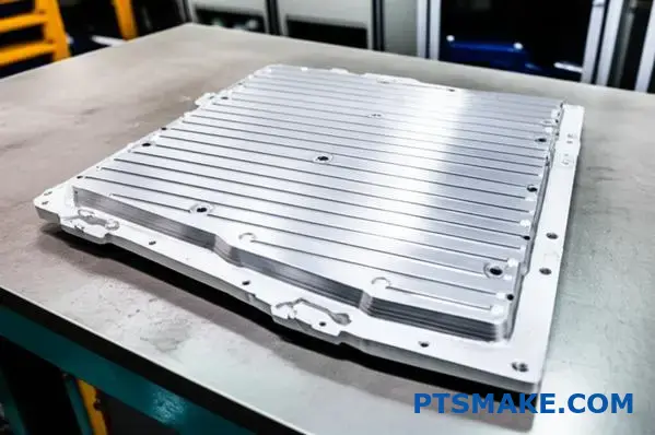
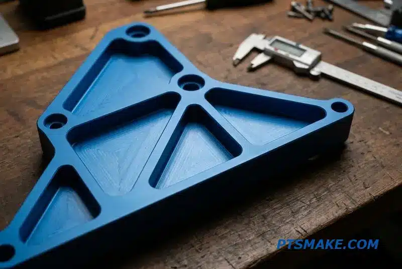
A Practical Design Concept
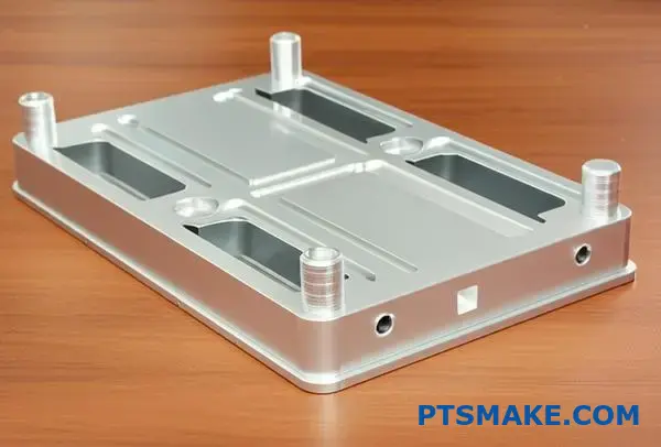
In my experience, a stamped aluminum liquid cooling plate with serpentine channels is a strong choice. This design directly addresses the core challenges we face in EV applications.
This method involves stamping or hydroforming thin aluminum sheets. These sheets are then brazed together to create sealed internal channels for the coolant flow.
Addressing Key Challenges
So, how does this design solve the problems?
First, the serpentine channel pattern ensures the coolant flows across the entire plate surface. This is critical for achieving excellent temperature uniformity for all battery cells, preventing hot spots.
Second, the plate itself can be designed as a structural component. It can be integrated directly into the battery pack tray. This simplifies assembly and greatly enhances vibration resistance.
| Feature | Benefit |
|---|---|
| Stamped Aluminum | Lightweight and cost-effective for scale. |
| Serpentine Channels | Ensures uniform temperature distribution. |
| Brazed Assembly | Creates a strong, leak-proof component. |
| Structural Integration | Reduces complexity and total parts count. |
This integration is key for mass production. It lowers both assembly time and overall cost. The choice of coolant is also critical, as its volumetric heat capacity7 impacts how much energy it can absorb and move away from the cells.
Our work on similar projects shows that this approach provides the best balance. It meets thermal needs without making the battery pack too heavy or expensive. At PTSMAKE, we focus on achieving this balance through precise manufacturing.
A stamped aluminum liquid cooling plate with serpentine channels offers a balanced solution. It effectively manages large surface areas, ensures temperature uniformity, integrates structurally, and remains cost-effective for mass production, addressing all key design challenges for modern EVs.
How do you optimize a data center cooling plate for efficiency?
Optimizing for efficiency means looking at the Total Cost of Ownership (TCO). It’s not just about getting the lowest temperature. The real goal is a perfect balance.
The Real Balancing Act
You must weigh thermal efficiency against pumping power. A design with complex internal channels might cool better. But it also demands more energy to push the fluid through.
Finding the Sweet Spot
This trade-off is critical for any liquid cooling plate. A very effective plate could result in high energy bills. We aim to find the most cost-effective operating point over the long run.
| Factor | Low Flow Rate | High Flow Rate |
|---|---|---|
| Thermal Performance | Lower | Higher |
| Pumping Power | Low | High |
| Operational Cost | Low | High |
Using Simulation to Predict Performance
So, how do we find this ideal balance? We use powerful simulation tools. Computational Fluid Dynamics (CFD) is fundamental to this process.
CFD modeling shows us exactly how fluid and heat behave inside the liquid cooling plate. This happens before we even machine a prototype. We can see pressure drops and identify hot spots.
This lets us fine-tune internal channel designs. We can adjust features to reduce the hydraulic resistance8 without sacrificing necessary thermal performance. This directly lowers the final pumping power requirement.
Modeling the Entire System
An optimized plate alone isn’t enough. We must consider its role in the larger cooling loop. This is where system-level modeling comes in. It accounts for pumps, tubing, and connectors.
At PTSMAKE, this holistic view is part of our process. It helps us predict real-world TCO accurately. We ensure the component we deliver integrates perfectly and performs efficiently within the client’s complete assembly, avoiding expensive issues later.
| Design Parameter | Simulation A (Cost-focus) | Simulation B (Perf-focus) |
|---|---|---|
| Max Temperature | 65°C | 61°C |
| Pressure Drop | 0.2 bar | 0.5 bar |
| Est. Pumping Power | 50W | 120W |
| TCO (3-Year) | Lower | Higher |
This data-driven approach guarantees we find the most economical solution across the product’s entire lifecycle.
Optimizing for TCO means balancing thermal performance against pumping power. Using tools like CFD and system modeling is essential to pinpoint the most efficient design, reducing both manufacturing and long-term operational costs for our clients.
How do you manage temperature uniformity across a large area?
Maintaining a consistent temperature on a large, non-uniformly heated surface is a significant engineering challenge. Hot spots can cause performance issues or failures.
At PTSMAKE, we don’t apply a one-size-fits-all solution. Instead, we use advanced design techniques for our liquid cooling plate solutions to direct cooling precisely where it’s needed most. This ensures optimal performance across the entire area.
Key Design Strategies
| Technique | Primary Goal | Best For |
|---|---|---|
| Flow Path Optimization | Direct coolant to hot spots | Concentrated heat loads |
| Variable Channel Width | Adjust flow velocity | Gradual temperature gradients |
| Multi-Zone Cooling | Isolate thermal zones | Multiple, distinct heat sources |
A Deeper Look at Advanced Cooling Techniques
Tackling non-uniform heat requires more than just a standard liquid cooling plate. It demands a tailored engineering approach. We often start with detailed thermal simulation to map the heat sources accurately.
Optimizing the Coolant’s Journey
Flow path optimization is about creating a smarter route for the coolant. Instead of a simple path, we design complex, serpentine channels. These paths force the fluid to spend more time in the hottest areas, absorbing more thermal energy. This is a common strategy in our designs.
Adjusting the Flow Dynamics
Another effective method is using variable channel widths. By narrowing a channel, we increase the coolant’s velocity. This enhances the local heat transfer rate. Conversely, wider channels slow the fluid down. This precise control over Laminar Flow9 helps us fine-tune the temperature profile.
Comparing Advanced Cooling Methods
| Method | Complexity | Cost Impact | Precision |
|---|---|---|---|
| Flow Path Optimization | Medium | Low to Medium | High |
| Variable Channels | Medium | Medium | Very High |
| Multi-Zone Cooling | High | High | Maximum |
Multi-zone cooling involves creating independent cooling loops for different sections of the plate. This offers the highest level of control but also adds complexity to the system. In past projects, we’ve used this for high-power electronics with multiple, distinct heat-generating components.
Effectively managing non-uniform heat requires advanced design strategies. By optimizing flow paths, varying channel widths, and implementing multi-zone systems, we can engineer a liquid cooling plate that delivers precise temperature control across any large surface, ensuring component reliability and performance.
What are the future trends in liquid cooling plate technology?
The future of liquid cooling plates is not just an evolution. It’s a complete revolution in thermal management. We are moving beyond simple milled channels.
The next generation focuses on maximizing surface area and efficiency. This is where innovation truly shines.
Key Future Innovations
Advanced manufacturing, like 3D printing, is a game-changer. It allows for incredibly complex internal geometries. Novel materials and embedded two-phase cooling are also on the horizon. These promise huge performance gains.
| Technology | Current Approach | Future Approach |
|---|---|---|
| Manufacturing | CNC Machining | 3D Printing |
| Cooling Method | Single-Phase | Two-Phase |
| Materials | Copper, Aluminum | Composites, Graphene |
| Control | External Sensors | Integrated Sensors |
These shifts will redefine what’s possible for a liquid cooling plate.
The push for more power in smaller packages is driving thermal innovation. At PTSMAKE, we see clients demanding cooling solutions that were once considered theoretical. The future trends directly address these challenges.
Advanced Manufacturing Unlocks Potential
3D printing, or additive manufacturing, is leading the charge. It allows us to create intricate internal lattice structures. These designs are impossible with traditional CNC machining. The result is a much higher surface area for heat dissipation.
The Power of Two-Phase Cooling
Embedded two-phase cooling represents a massive leap in efficiency. Instead of just heating liquid, this method allows it to boil. The phase change from liquid to vapor absorbs enormous amounts of heat through a process called nucleate boiling10. This can dramatically improve cooling performance without increasing flow rates.
Novel Materials and Smart Integration
We’re also exploring new materials. Copper-diamond composites, for example, offer thermal conductivity far beyond traditional metals.
Finally, integrating sensors directly into the liquid cooling plate is crucial. This creates "smart" hardware that provides real-time data on temperature and flow. This enables predictive maintenance and dynamic performance optimization.
| Future Trend | Primary Benefit |
|---|---|
| 3D Printing | Complex geometries, maximized surface area. |
| Two-Phase Cooling | Highly efficient heat absorption. |
| Novel Materials | Superior thermal conductivity. |
| Integrated Sensors | Real-time monitoring and control. |
Future liquid cooling plates will be smarter, more efficient, and highly customized. Key trends include 3D printing for complex designs, two-phase cooling for superior heat absorption, advanced materials, and integrated sensors for real-time optimization.
Take Your Liquid Cooling Plate Project Further with PTSMAKE
Ready to elevate your next-generation liquid cooling plate? Partner with PTSMAKE for precision manufacturing, expert engineering support, and hassle-free project execution. Send us your drawings or RFQ today—transform your ideas into reliable, production-ready reality with a manufacturer trusted worldwide!

Learn how this key metric impacts the efficiency of your entire cooling system. ↩
Learn how this flow type maximizes heat transfer efficiency in our designs. ↩
Learn the engineering principles behind creating a perfect, leak-proof bond for critical fluid applications. ↩
Learn more about this dimensionless quantity used to predict fluid flow patterns in different situations. ↩
Learn how flow rate calculations directly influence thermal performance in your cooling system. ↩
Discover how this thermal concept influences the design and material choice for cooling solutions. ↩
Understand how this coolant property influences the overall efficiency of the thermal management system. ↩
Discover how this key metric influences pump choice and long-term operational costs in your cooling system. ↩
Learn how different fluid behaviors directly influence the efficiency of your cooling system. ↩
Learn more about this highly efficient heat transfer phenomenon. ↩