You’ve likely faced the frustration of overheating electronics despite installing what seemed like adequate cooling solutions. The problem often lies in choosing the wrong heat sink material or design, leading to thermal throttling, reduced component lifespan, and system failures.
Copper heat sinks offer superior thermal conductivity (~400 W/m·K) compared to aluminum alternatives, enabling rapid heat spreading and efficient thermal management for high-power applications like CPUs, power electronics, and LED systems.
After working with thermal management solutions at PTSMAKE, I’ve compiled this comprehensive guide to help you understand copper heat sinks from first principles to practical implementation. This guide covers everything from material science fundamentals to real-world case studies that will help you make informed decisions for your next thermal challenge.
Why is copper’s thermal conductivity critical for heat sink performance?
Copper boasts a thermal conductivity of approximately 400 W/m·K. This value is significantly higher than many alternative materials used in manufacturing. It is not just a specification on a datasheet; it defines thermal capability.
In our testing results at PTSMAKE, we found that this property is the primary driver for efficient heat removal. It determines how effectively a copper heat sink can evacuate thermal energy from high-power components.
| Material | Thermal Conductivity (W/m·K) | Relative Performance |
|---|---|---|
| Copper | ~400 | High |
| Aluminum (6061) | ~167 | Medium |
| Stainless Steel | ~16 | Low |
When dealing with modern processors, every degree matters. The high conductivity ensures that the heat does not linger near the sensitive die.
null
Overcoming the Barrier of Spreading Resistance
The true value of copper lies in its ability to mitigate spreading resistance. A heat source, like a CPU, is often much smaller than the heat sink base.
If the base material conducts poorly, heat concentrates directly underneath the chip. This creates a "hot spot" while the edges of the heat sink remain cool.
In past projects at PTSMAKE, we observed that copper minimizes this delta. It forces the heat to travel outwards to the edges of the base rapidly.
The Highway Analogy
To understand this, visualize a highway system during rush hour. Aluminum acts like a road with traffic lights; the cars (heat) move, but there is friction and delay.
Copper acts as a wide, open freeway. The thermal energy flows without restriction, reaching the destination instantly. This high thermal diffusivity1 is crucial for transient loads.
| Feature | Aluminum Base | Copper Base |
|---|---|---|
| Heat Distribution | Localized near the source | Uniform across the base |
| Fin Utilization | Outer fins remain cool | All fins participate equally |
Maximizing Fin Efficiency
Because the heat reaches the extremities of the base quickly, the outer fins become active participants in cooling.
In aluminum designs, the outer fins often do very little work because the heat never reaches them effectively.
By using copper, we ensure that the entire surface area of the heat sink contributes to convection, maximizing total cooling potential.
Summary
Copper’s exceptional conductivity is the key to overcoming spreading resistance. It allows heat to distribute evenly across the base, ensuring that every fin on a copper heat sink is utilized effectively. This creates a more efficient thermal management system compared to aluminum.
3. How does copper purity (e.g., C11000) impact thermal performance?
In our work at PTSMAKE, we often see engineers specify "copper" without defining the grade. This oversight can limit your thermal results.
Purity is measured against the International Annealed Copper Standard (IACS). Higher percentages mean better conductivity.
For a high-performance copper heat sink, selecting the right grade is critical.
Here is a quick comparison of common grades we machine:
| Grade | Common Name | Purity | IACS % |
|---|---|---|---|
| C10100 | Oxygen-Free Electronic (OFE) | 99.99% | 101% |
| C11000 | Electrolytic Tough Pitch (ETP) | 99.90% | 100% |
C10100 offers slightly better performance due to lower oxygen content. However, C11000 is the industry standard for most general applications.
When we machine a copper heat sink, the internal structure dictates performance. Think of the copper lattice as a highway.
Electrons transfer heat along this highway. In pure copper like C10100, traffic flows smoothly.
However, oxygen or other trace elements in C11000 act as roadblocks. These impurities scatter the electrons.
This disruption impedes the flow, increasing thermal resistance.
This phenomenon is often described by Matthiessen’s rule2, which explains how impurities add to total resistivity.
Even a small amount of oxygen disrupts the lattice structure.
In our internal comparisons at PTSMAKE, we noted distinct differences in material properties.
| Property | C10100 (OFE) | C11000 (ETP) |
|---|---|---|
| Oxygen Content | ~0.0005% | ~0.04% |
| Thermal Conductivity | ~391 W/m·K | ~388 W/m·K |
| Risk of Hydrogen Embrittlement | Low | High |
While the conductivity gap seems small, it matters in high-flux density applications.
Impurities confuse the path of heat transfer. This results in higher junction temperatures for your device.
Choosing between C10100 and C11000 depends on your specific thermal requirements. While C11000 is sufficient for standard heat sinks, C10100 provides necessary efficiency for sensitive electronics. Purity ensures the lattice structure remains clear for optimal heat dissipation.
What is the role of surface finish and flatness?
When we mount a cooling solution, the physical interface between the heat source and the base is often a major thermal bottleneck. Even if a machined surface appears smooth to the naked eye, it is actually full of microscopic irregularities.
These imperfections create tiny pockets of air between the component and the metal base. Unfortunately, air is an exceptionally poor conductor of heat compared to solid metal.
Thermal Conductivity Comparison
| Material | Conductivity (W/m·K) | Impact on Heat Transfer |
|---|---|---|
| Air (The Gap) | ~0.026 | Blocks Heat Flow |
| Thermal Paste | ~1 – 8 | Bridges the Gap |
| Copper Heat Sink | ~385 | Conducts Efficiently |
We must address these gaps to ensure the copper heat sink functions correctly. If the surface is too rough, heat accumulates at the source rather than dissipating.
Optimizing Contact for Maximum Efficiency
To combat the issue of air gaps, we utilize precision manufacturing processes such as lapping and polishing. These techniques serve to significantly improve both surface finish and overall flatness.
The primary objective is to maximize the actual metal-to-metal contact area. In our past projects at PTSMAKE, we have observed that superior flatness directly correlates with lower operating temperatures.
By achieving a flatter surface, we minimize the reliance on Thermal Interface Materials (TIM). While TIMs are essential for filling microscopic voids, they possess higher thermal resistance than the base metal.
The Relationship Between Flatness and TIM
Ideally, the TIM layer should be as thin as possible to reduce thermal resistance.
| Machining Method | Surface Flatness | Required TIM Thickness |
|---|---|---|
| Standard Milling | Good | Thick Layer |
| Precision Grinding | Better | Moderate Layer |
| Lapping / Polishing | Best | Minimal Layer |
Microscopic Surface Dynamics
When we refine the surface finish, we are essentially reducing the height of microscopic asperities3 on the metal.
If these peaks remain too high, they prevent the copper heat sink from sitting flush against the processor or heat source.
Through rigorous testing with our clients, we know that a polished surface allows heat to transfer rapidly into the cooling fins. This mechanical precision is just as critical as the material selection itself.
In summary, surface finish and flatness are critical for overcoming thermal bottlenecks. Microscopic air gaps act as insulators, but precision lapping reduces these voids. This allows for a thinner TIM layer, ensuring the copper heat sink extracts heat efficiently from the source.
What are the inherent physical limitations of copper heat sinks?
While we value copper for its exceptional thermal conductivity, it is not a perfect solution for every application. In my experience at PTSMAKE, two major physical hurdles often surprise engineers during the design phase: weight and material cost.
Copper is significantly denser than aluminum. This adds mechanical stress to printed circuit boards (PCBs) and requires robust mounting solutions. Furthermore, the raw material price is consistently higher, impacting the final budget.
| Limitation | Description | Impact on Design |
|---|---|---|
| High Density | Approx. 8.96 g/cm³, roughly 3x heavier than aluminum. | Requires stronger mounting hardware and structural support. |
| Material Cost | Market prices are higher compared to aluminum alloys. | Increases the overall Bill of Materials (BOM) cost. |
We must look beyond just the material properties of the metal itself. A copper heat sink can conduct heat rapidly from the heat source to the fins. However, transferring that heat from the fins into the surrounding air is a different challenge.
Air is actually a relatively poor thermal conductor. If the airflow is restricted or stagnant, the heat simply accumulates around the fins. We often refer to this situation as a "performance plateau" in passive designs.
No matter how much copper you add, physics dictates a limit. In our testing labs, we observe that increasing surface area eventually yields diminishing returns. This is largely governed by the convective heat transfer coefficient4.
When the air cannot carry heat away fast enough, the sink becomes heat-saturated. This is why we often suggest active cooling or liquid solutions for high-wattage density applications.
| Factor | Effect on Cooling | Limitation Source |
|---|---|---|
| Air Viscosity | Creates boundary layers that insulate fins. | Fluid Dynamics |
| Flow Rate | Determines the speed of heat removal. | Fan Capacity / Natural Convection |
| Ambient Temp | Sets the baseline temperature delta. | Environment |
In past projects, I have seen designs fail because the focus was solely on the metal’s conductivity. We cannot ignore the interaction with the surrounding airflow. Understanding these limits is crucial for successful precision manufacturing.
To summarize, while the high density and cost of a copper heat sink present logistical challenges, the ultimate performance ceiling is often defined by airflow properties. We must optimize the interaction between the metal surface and the cooling medium to ensure efficiency.
From first principles, when is aluminum a better choice?
When we approach thermal engineering from first principles, density becomes a governing factor. While a copper heat sink offers superior conductivity, its mass is often prohibitive. In our experience at PTSMAKE, weight constraints frequently dictate the design before thermal limits are even reached.
For aerospace or mobile robotics, every gram affects battery life and dynamics. Aluminum provides a necessary cooling solution without the heavy penalty of copper.
Let’s compare the physical impact:
| Material | Density ($g/cm^3$) | Weight Consequence |
|---|---|---|
| Aluminum (6061) | ~2.70 | Ideal for flight/motion |
| Copper (C11000) | ~8.96 | High (3.3x penalty) |
If your hardware needs to fly, move quickly, or hang vertically, aluminum is usually the logical winner.
Diminishing Returns in Low-Load Scenarios
Not every electronic component requires maximum dissipation. For chips generating moderate heat, swapping to a copper heat sink often yields diminishing returns. The junction temperature might drop slightly, but the cost and weight spike disproportionately.
At PTSMAKE, we advise clients to look at the entire thermal path. If the bottleneck is the airflow or the interface material, a premium metal won’t solve the problem.
Mechanical Stress in Rack Systems
In large rack-mounted systems, gravity creates mechanical challenges. A heavy copper block applies significant torque to the PCB. Over time, this causes board warping or solder joint failures, especially during shipping vibrations.
Aluminum minimizes this structural risk. It ensures the cooling assembly is secure without requiring reinforced mounting brackets.
Heat Capacity and Transient Response
There is a nuance in thermodynamics regarding how materials store energy. Aluminum actually has a higher specific heat capacity by weight compared to copper. This directly influences the thermal diffusivity5 of the system.
For applications with short bursts of heat rather than continuous loads, aluminum is surprisingly effective.
Operational Trade-off Matrix
| Constraint | Aluminum Advantage | Copper Limitation |
|---|---|---|
| Budget | Cost-effective scaling | Expensive raw material |
| Vibration | Low inertia | High stress on mounts |
| Heat Spikes | High absorption per kg | Lower storage per kg |
| Machinability | Fast production | Slower, tool-wearing |
In scenarios involving intermittent operation, aluminum acts as an excellent thermal buffer, absorbing energy efficiently per unit of mass.
Choosing between aluminum and a copper heat sink isn’t just about conductivity numbers. Aluminum reigns supreme in weight-critical aerospace applications and prevents mechanical damage in rack systems. Furthermore, for intermittent loads, its superior specific heat per kilogram offers better efficiency without the high cost of copper.
How does a copper base function as a heat spreader?
In high-performance electronics, we face a significant challenge known as heat flux density. A powerful chip generates massive energy within a tiny surface area.
This creates a dangerous "hot spot" where temperatures spike rapidly. If we do not manage this concentration, the component fails.
At PTSMAKE, we often visualize this thermal challenge for our clients using the following comparison.
Heat Flux Dynamics
| Component | Surface Area | Heat Concentration | Risk Level |
|---|---|---|---|
| Processor Die | Very Small | Extremely High | Critical |
| Heat Sink Base | Large | Low (Passive) | Safe |
We must rapidly move energy from that small die to a wider area.
Lateral Thermal Conduction
Why do we specifically recommend a copper heat sink base for these applications? It is not just about raw cooling power.
It is about the speed of lateral transfer.
When heat hits a copper base, the material’s high conductivity allows energy to flow sideways instantly.
This process spreads the intense heat over the entire footprint of the base plate.
Spreading Efficiency Analysis
| Material Property | Copper Behavior | Aluminum Behavior | Impact on Hot Spot |
|---|---|---|---|
| Conductivity | High (>390 W/m·K) | Moderate (~205 W/m·K) | Rapid reduction |
| Lateral Spread | Fast & Uniform | Slower & Localized | Eliminates spikes |
| Thermal Mass | High | Low | Buffer against surges |
Overcoming Resistance
In our experience with complex assemblies, using a copper base is the best way to reduce Thermal Constriction Resistance6.
Without this rapid spreading, the outer fins of a cooling solution remain cold and useless.
The copper base acts as a thermal highway. It expands the path for heat, delivering it evenly to the fins.
This ensures that every square inch of your cooling array is actively working to dissipate energy.
A copper base effectively transforms a concentrated thermal load into a manageable, distributed flow. By rapidly spreading heat laterally, it prevents local overheating and optimizes the performance of the connected cooling fins, ensuring long-term reliability for high-power devices.
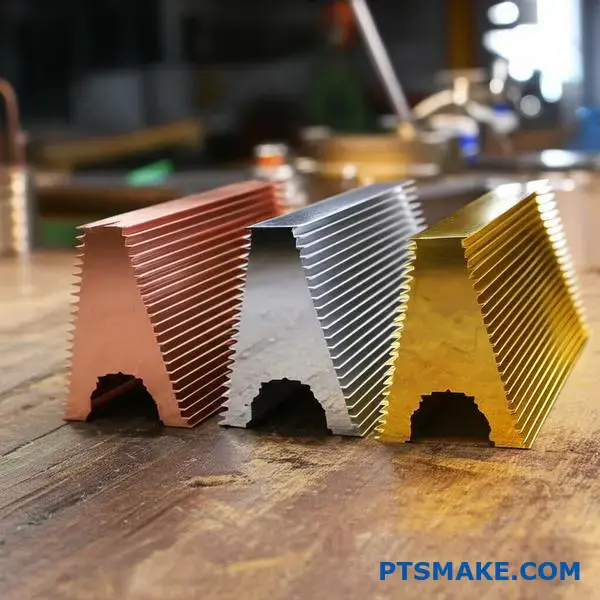
Are copper alloys used, and what are the trade-offs?
Pure copper offers the best thermal performance for a custom copper heat sink. However, it is soft and gummy to machine. Sometimes, mechanical strength matters more than just maximum heat transfer.
In our experience at PTSMAKE, we often suggest alloys when durability is key. Adding elements improves hardness but reduces conductivity. It is a balancing act between structure and thermal performance.
| Material | Thermal Conductivity | Machinability | Hardness |
|---|---|---|---|
| Pure Copper (C11000) | Excellent | Poor (Gummy) | Low |
| Tellurium Copper | Good | Excellent | Medium |
| Beryllium Copper | Fair | Good | High |
When designing a complex copper heat sink, you might encounter specific physical constraints. Pure copper (C10100 or C11000) is standard, but it deforms easily under high stress.
In past projects, we have utilized Tellurium Copper (C14500) for parts requiring complex CNC machining. It creates short chips rather than long strings. This makes production faster and surface finishes smoother.
However, thermal conductivity drops by about 10% to 20% compared to pure copper. It is a worthy trade-off for intricate geometries where precision is non-negotiable.
Then there is Beryllium Copper (BeCu). This material is incredibly strong. It achieves its distinct hardness through precipitation hardening7.
We often see BeCu used in spring contacts or connectors that also need to dissipate heat. It withstands repeated physical stress without losing shape.
| Alloy Type | Primary Benefit | Typical Application | Thermal Trade-off |
|---|---|---|---|
| Tellurium Copper | High Machinability | Complex nozzles, intricate fins | Moderate Loss |
| Beryllium Copper | High Strength & Elasticity | Spring clips, structural sinks | Significant Loss |
Based on tests with our customers, pure copper remains king for absolute thermal efficiency. Yet, alloys solve structural problems that pure copper cannot handle alone.
Choosing the right material depends on your specific priorities. Pure copper maximizes heat transfer but lacks mechanical strength. Alloys like Tellurium and Beryllium copper improve machinability and durability significantly. However, they sacrifice some thermal conductivity. We assist clients in finding the perfect balance for their application.
What are the common manufacturing processes for copper heat sinks?
Selecting the right manufacturing method is crucial for balancing thermal performance and production costs. At PTSMAKE, we categorize these processes based on the required geometry and volume.
We guide clients through these options to ensure the final copper heat sink meets their specific design goals. Here is a breakdown of the primary techniques we utilize.
| Process | Key Characteristic | Best Application |
|---|---|---|
| Skiving | Continuous material | High-density fin stacks |
| Forging | High pressure shaping | Pin fins & mass production |
| CNC Machining | Subtractive manufacturing | Prototypes & complex bases |
| Bonding | Joined assembly | Tall fins & mixed materials |
Skiving Process
Skiving involves slicing thin layers from a solid copper block to form fins. Because the fins remain attached to the base, there is no joint layer to impede heat transfer.
In our testing, skived copper heat sinks consistently outperform bonded alternatives in high-heat flux applications due to this continuous material structure.
Cold Forging
This process uses high pressure to force copper into a die. It creates parts with excellent structural integrity. The grain structure of the copper remains aligned, which improves thermal conductivity.
We often suggest forging for pin fin designs where airflow comes from multiple directions. It becomes very cost-effective once tooling is established.
CNC Machining
CNC machining provides the highest precision. At PTSMAKE, we use it heavily for prototyping and low-volume runs where custom features are needed.
While it generates more waste, it allows for geometries that molds cannot easily produce. It is the go-to method for validating a design before mass production.
Bonding and Brazing
For designs requiring very tall fins, we bond separate fins to a grooved base. The challenge here is minimizing the interface thermal resistance8 at the joint.
Brazing uses a metal filler to create a strong, conductive link. This method allows us to combine different manufacturing techniques for optimal cooling performance.
| Feature | Skiving | Forging | CNC Machining |
|---|---|---|---|
| Material Efficiency | High | High | Low |
| Setup Cost | Moderate | High | Low |
| Design Flexibility | Limited | Moderate | Very High |
Each manufacturing process creates a copper heat sink with unique thermal characteristics. Whether you need the high fin density of skiving, the structural strength of forging, or the precision of CNC machining, understanding these mechanics ensures you select the most efficient solution for your hardware.
How does manufacturing process impact performance, cost, and design freedom?
Choosing the right production method defines your product’s success. It is not just about shaping metal; the process directly dictates thermal efficiency and your budget.
At PTSMAKE, we often see how a simple choice changes everything. A copper heat sink made by skiving behaves differently than one machined from a solid block.
Performance vs. Cost Trade-offs
| Process | Fin Density | Tooling Cost |
|---|---|---|
| CNC Machining | Medium | Low |
| Skiving | High | Medium |
| Forging | Medium | High |
We need to balance these factors carefully. High performance usually demands specific manufacturing techniques. Let’s look at the detailed breakdown below.
Analyzing the Manufacturing Matrix
We need to look beyond the surface. The method used determines the structural integrity of the copper heat sink.
For instance, bonded fins offer design freedom. However, they introduce a barrier. This barrier affects heat transfer efficiency significantly.
Process Capability Comparison
| Process | Aspect Ratio | Base-Fin Resistance | NRE Cost | Unit Cost (Vol) |
|---|---|---|---|---|
| Skiving | High (>50:1) | Zero (Monolithic) | Moderate | Moderate |
| Cold Forging | Low (<10:1) | Zero (Monolithic) | High | Low |
| CNC Machining | Medium | Zero (Monolithic) | Low | High |
| Bonded Fin | High | High (Glued/Brazed) | Low | Moderate |
The Hidden Impact of Joints
Processes like skiving or machining create parts from a single block. This effectively eliminates Thermal Contact Resistance9.
In our past projects, we found that eliminating joints improves thermal conductivity by a measurable margin.
Forging is excellent for high volume. But, it limits the fin height. You sacrifice surface area for lower unit costs.
Machining offers the best precision. Yet, it consumes more time per unit. It is ideal for prototypes but costly for mass production.
At PTSMAKE, we guide clients to balance these constraints. We ensure the design intent matches the manufacturing reality.
Manufacturing processes dictate the limitations of your copper heat sink. While skiving and machining offer superior thermal performance through continuous material, forging excels in cost reduction for high volumes. You must align your thermal goals with the specific capabilities of each production method.
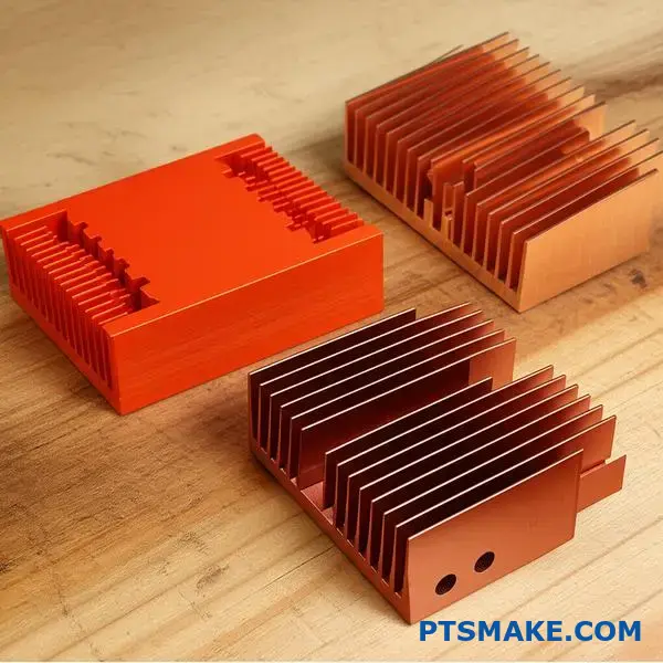
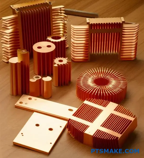
What are the main structural types of copper heat sinks?
When selecting a copper heat sink, the specific geometry of the fins dictates performance. The structure determines how air moves through the device and how effectively heat is dissipated.
At PTSMAKE, we categorize these structures into three primary groups based on their physical design.
| Structural Type | Primary Manufacturing Method | Ideal Airflow Scenario |
|---|---|---|
| Plate Fin | Skiving or Extrusion | Linear, forced airflow |
| Pin Fin | Cold Forging or Machining | Multi-directional airflow |
| Flared Fin | Cold Forging | Limited vertical height |
Each type offers distinct advantages depending on the available space and fan configuration. Let’s explore how these geometries function in practical applications.
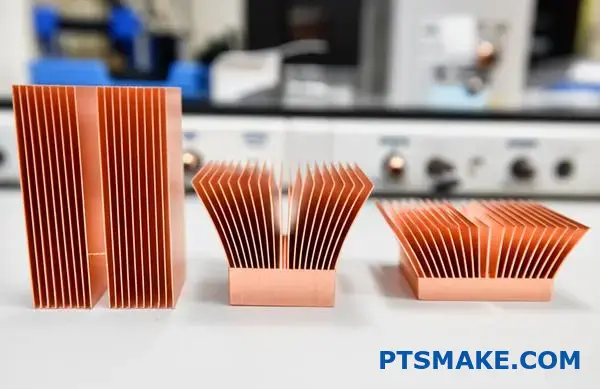
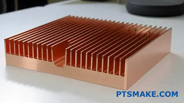
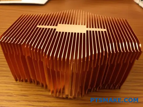
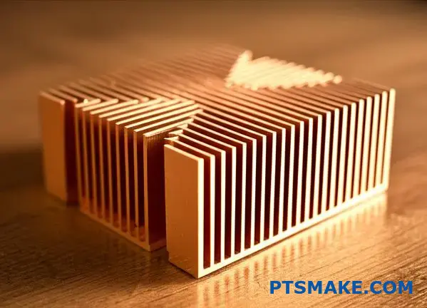
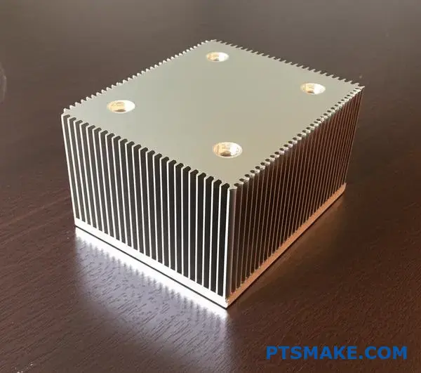
Plate Fin Copper Heat Sinks
These are the most traditional structures we encounter. They consist of straight, continuous walls running along the base.
We typically use skiving technology to manufacture these. This method allows for thinner fins and a higher density compared to extrusion.
The airflow characteristic is strictly linear. To work effectively, the air must pass directly through the channels. This structure offers low hydraulic resistance but requires directed airflow.
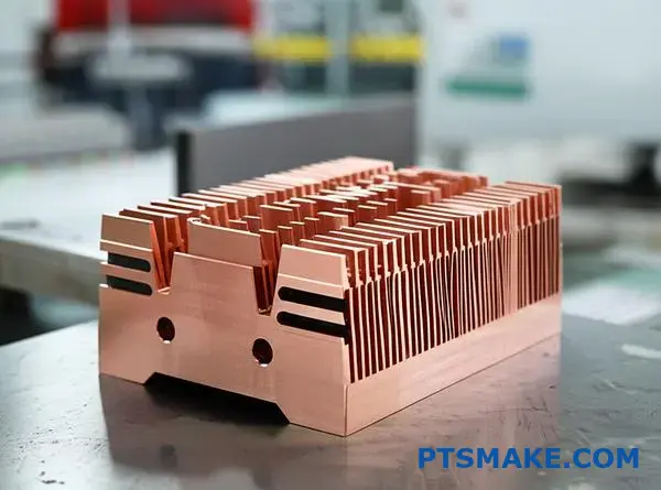
Pin Fin Copper Heat Sinks
Instead of continuous walls, this design utilizes an array of individual pins. These pins can be cylindrical, square, or elliptical.
In our experience with cold forging projects, pin fins are excellent for environments with unpredictable airflow. Air can enter the array from any direction.
This geometric arrangement promotes significant turbulence10 around the pins. While this increases pressure drop, it often enhances heat transfer rates in low-velocity environments.
| Characteristic | Plate Fin | Pin Fin |
|---|---|---|
| Airflow Path | Straight Channel | Cross-flow capable |
| Pressure Drop | Low | Moderate to High |
| Manufacturing | Skiving is common | Forging is common |
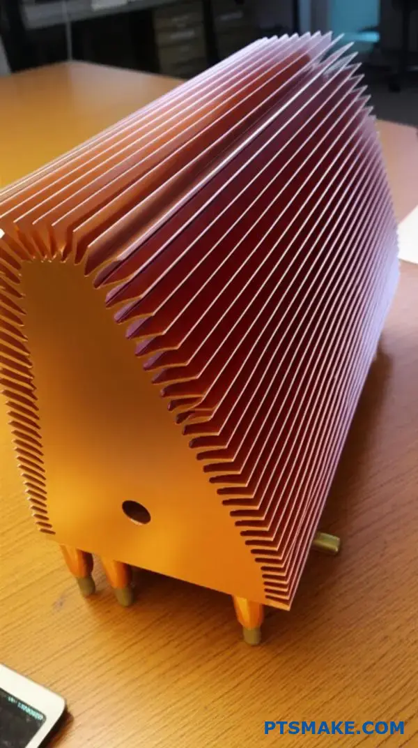
Flared Fin Designs
These are a variation of the pin fin. The pins splay outward as they extend from the base.
This structure increases the surface area at the top of the heat sink. We recommend this design when vertical clearance is tight, but there is ample horizontal space to utilize.
Selecting the correct structural type is crucial for thermal management. Plate fins are best for linear airflow, whereas pin fins offer versatility with omnidirectional air entry. Flared fins solve space constraints by maximizing surface area. Matching the copper heat sink geometry to your airflow strategy ensures optimal cooling.
How does fin geometry influence cooling efficiency?
Fin geometry is the heart of thermal management. When we design a high-performance copper heat sink, we are not just shaping metal. We are strictly managing airflow and heat dissipation paths to ensure reliability.
At PTSMAKE, we focus on four critical dimensions during the design phase.
Key Geometric Parameters
| Parameter | Function | Impact on Cooling |
|---|---|---|
| Height | Increases total surface area | Can block air in tight spaces |
| Thickness | Conducts heat upwards | Adds weight and material cost |
| Pitch | Airflow channel width | Balances pressure drop |
| Profile | Shape optimization | Affects turbulence creation |
Getting these parameters right ensures your device survives thermal stress. It is a delicate balancing act between physical size and aerodynamic performance.
More surface area generally implies better cooling potential. However, simply packing fins tighter often leads to diminishing returns.
The Surface Area Trap
If fins are too close, the back pressure increases significantly. The system fan struggles to push air through the dense array.
In our testing results at PTSMAKE, we found that optimal spacing is crucial. You need enough gap for air to move freely without choking the system.
Managing Airflow Resistance
When air moves across a flat surface, it tends to stick. This creates a stagnant layer of air that insulates the heat rather than removing it.
This phenomenon is closely related to the hydraulic diameter11. It defines how effective the channel geometry is for fluid flow.
Disrupting the Flow
We design fin profiles specifically to break this insulating layer. Using serrated or pin fins creates necessary turbulence.
| Design Goal | Mechanism | Result |
|---|---|---|
| Disruption | Break laminar flow | Higher heat transfer coefficient |
| Optimization | Balanced fin pitch | Lower fan noise and speed |
Turbulence mixes cool air with the hot surface layer. This significantly improves thermal efficiency compared to smooth laminar flow found in basic designs.
Complex geometries in CNC machining allow us to maximize this effect. We ensure the copper heat sink performs efficiently even under heavy thermal loads.
Balancing fin height, thickness, and pitch is essential for optimal thermal performance. We must trade maximum surface area for adequate airflow to prevent choking the system. Understanding flow dynamics allows us to manufacture efficient copper heat sink solutions that maintain reliability.
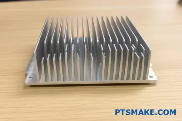
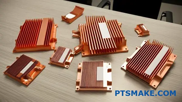
What are hybrid heat sinks and their structural purpose?
When tackling high-performance cooling challenges, we often face a material dilemma. Pure copper is heavy, while pure aluminum lacks rapid spreading speed.
The solution lies in hybrid designs.
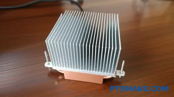
These heat sinks typically feature a copper base plate bonded to aluminum fins. This structure leverages the strengths of both metals to optimize thermal management.
Here is how we split the roles:
| Component | Material | Primary Function |
|---|---|---|
| Base Plate | Copper | Rapid heat absorption and spreading |
| Cooling Fins | Aluminum | Heat dissipation and weight reduction |
By placing copper only where the heat flux is highest, we maximize efficiency without adding unnecessary bulk.
The heat flux is most intense directly above the processor or power source.
In our projects at PTSMAKE, we find that a solid aluminum block often creates a "hot spot" because it cannot move energy fast enough.
This is where the copper base excels.
It rapidly pulls heat away from the source, spreading it laterally across a wider area.
Once the heat is distributed, heavy copper becomes unnecessary.
We switch to aluminum fins for the dissipation stage.
Aluminum is lighter and cheaper, allowing us to increase the fin density without making the copper heat sink assembly too heavy to mount.
Structural Integrity and Bonding
Connecting these two distinct metals is the real manufacturing challenge.
If the connection is weak, the thermal performance drops instantly.
We often analyze the thermal diffusivity12 of the base material to ensure it matches the application’s intensity.
Here is a comparison of assembly methods we use:
| Method | Bond Strength | Thermal Transfer | Cost Factor |
|---|---|---|---|
| Soldering | High | Good | Moderate |
| Epoxy Bonding | Low | Poor | Low |
| Swaging | Very High | Excellent | Moderate |
Swaging is often preferred for rugged environments.
It uses mechanical force to lock the aluminum fins into the copper base grooves.
This eliminates the risk of solder joints failing under thermal cycling, ensuring long-term reliability.
Hybrid heat sinks combine a copper base for rapid spreading with aluminum fins for efficient dissipation. This structure optimizes the thermal path while significantly reducing weight and material costs compared to solid copper solutions, provided the bonding method ensures low thermal resistance.
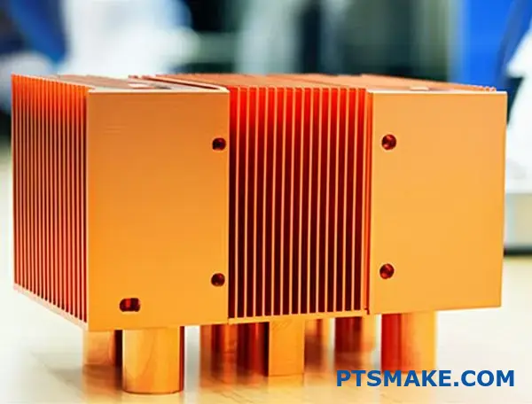
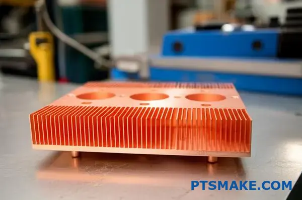
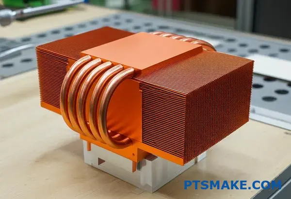
How are heat pipes structurally integrated and why?
We often refer to heat pipes as "heat superconductors" in the thermal management industry. They move thermal energy far faster than solid metal alone.
At PTSMAKE, we integrate them carefully to maximize their efficiency.
Usually, we machine precise grooves into a copper heat sink base. The pipes sit flush inside these channels.
| Component | Function |
|---|---|
| Heat Pipe | Rapid vapor-phase transport |
| Copper Base | Interface with the heat source |
| Groove | Increases contact surface area |
This setup ensures heat leaves the source immediately. It solves the lag often found in pure conduction methods.
The Embedding Process
Structural integration starts with precision CNC machining. We cut channels into the copper block that match the pipe’s radius perfectly.
If the fit is loose, air gaps will kill performance.
We apply a thin layer of high-conductivity solder. Then, we press the pipes into place under controlled heat.
Overcoming Distance Limits
Solid copper is excellent, but it struggles to move heat more than a few inches efficiently.
Heat pipes use capillary action13 internally to circulate fluid. This allows us to move heat to a remote fin stack located further away from the processor.
| Integration Method | Best Use Case | Benefit |
|---|---|---|
| Direct Touch | Budget coolers | Low cost, decent performance |
| Soldered Base | High-performance | Maximum thermal transfer |
| Epoxy Bonding | Low-temp apps | Easy assembly, lower stress |
Why Structure Matters
In our testing at PTSMAKE, a soldered connection outperforms a dry press-fit by a significant margin.
The solder bridges microscopic imperfections between the pipe and the base. This creates a continuous thermal path.
Without this tight integration, the "superconductor" effect is wasted at the interface.
To summarize, heat pipes act as superhighways for thermal energy. By soldering them into precise grooves within a copper heat sink, we overcome the distance limitations of solid conduction. This ensures heat reaches the cooling fins instantly for effective dissipation.
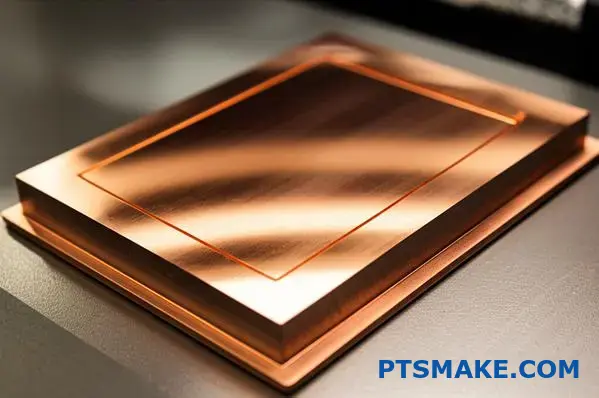
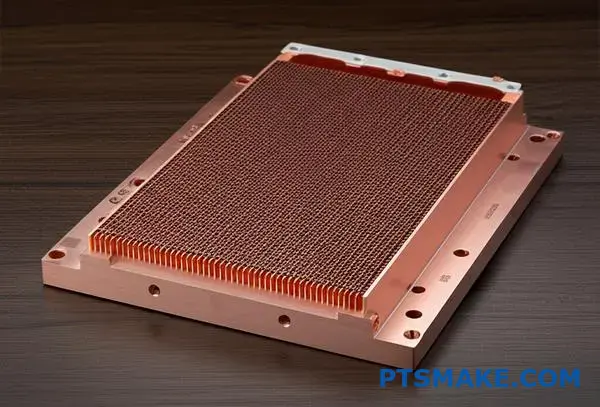
What is the structure of a copper vapor chamber?
Think of a vapor chamber as a planar, two-dimensional version of a standard heat pipe.
At PTSMAKE, we often describe it to our clients as the ultimate heat spreader for restricted spaces.
The core structure relies on three main components inside a vacuum-sealed copper envelope.
These components work together to manage high heat flux efficiently.
| Component | Function | Material |
|---|---|---|
| Envelope | Maintains vacuum and transfers heat | Oxygen-free Copper |
| Wick | Transports fluid via capillary action | Sintered Copper Powder |
| Working Fluid | Absorbs and releases latent heat | De-ionized Water |
This setup creates a completely sealed system.
It allows heat to spread evenly across the X and Y axes almost instantly.
The copper shell ensures durability while the internal mechanisms handle the thermal load.
The Mechanism of Phase Change
When a heat source contacts the base, the fluid at the hot spot evaporates immediately.
This vapor fills the chamber, utilizing the entire volume to spread heat.
It is far superior to solid copper conduction.
In our testing at PTSMAKE, we see near-instant temperature equalization.
This process transforms a point heat source into a uniform field.
Structural Integrity and Performance
The internal wick structure is critical for performance.
It usually consists of sintered copper powder to maximize surface area.
This structure supports the thin walls against atmospheric pressure.
It also drives the fluid back to the heat source.
This continuous cycle allows for rapid cooling of high-power components.
| Feature | Solid Copper | Vapor Chamber |
|---|---|---|
| Heat Transport | Conduction only | Phase change + Conduction |
| Spreading Direction | Linear (Hot to Cold) | Multi-directional (2D) |
| Thermal Resistance | High | Extremely Low |
Achieving Thermal Balance
The goal of this structure is to create Isothermalization14 across the base surface.
This ensures that the attached fins receive an even heat load.
It eliminates hot spots typical in high-density electronics.
We use copper because of its mechanical strength and compatibility with water.
This reliability is why we recommend it for critical hardware like a specialized copper heat sink.
In summary, a copper vapor chamber consists of a vacuum-sealed envelope, a sintered wick, and a working fluid. This structure enables rapid phase-change heat transfer, providing superior lateral spreading compared to solid metal. It is the ideal solution for managing high heat flux in compact devices.
How are copper heat sinks classified by their target application?
When I categorize a copper heat sink, looking at the end application is the most practical method.
Different industries demand specific thermal properties and manufacturing tolerances.
We generally group them into four main categories based on what they cool.
Here is a breakdown of these primary groups:
| Application | Typical Component | Key Goal |
|---|---|---|
| Computing | CPU / GPU | Hotspot reduction |
| Lighting | High-Power LED | Lumen maintenance |
| Power | IGBT / MOSFET | Steady dissipation |
| Telecom | Base Stations | Reliability |
At PTSMAKE, we see how these distinct needs dictate the manufacturing process, from skiving to precision CNC machining.
For computing applications like CPUs and GPUs, the thermal challenge is extreme power density in a very small area.
We often use copper bases combined with heat pipes or vapor chambers here.
The primary goal is to move heat away from the silicon die quickly.
High-power LEDs face a slightly different issue regarding longevity.
They require keeping junction temperatures low to prevent color shifts or premature failure.
We frequently machine pin-fin copper heat sinks for these to maximize surface area in natural convection setups.
Power electronics, such as IGBTs and MOSFETs, generate massive total heat loads rather than just concentrated spots.
Here, liquid cold plates or heavy copper bonded fin sinks are common solutions in our production line.
Telecommunications equipment requires long-term reliability in harsh outdoor environments.
We design these for minimal maintenance, often avoiding active fans.
An important concept across all these applications is thermal spreading resistance15.
Copper excels at minimizing this resistance compared to aluminum, which is vital for high-performance parts.
| Application | Design Feature | Thermal Challenge |
|---|---|---|
| CPU/GPU | Vapor Chambers | High Watt/cm² |
| LED | Pin Fins | Natural Convection |
| Power Electronics | Bonded Fins | High Total Wattage |
| Telecom | Thick Base | Environmental Exposure |
In our testing results, neglecting the specific application environment often leads to sub-optimal cooling performance.
Classifying copper heat sinks by application reveals distinct design priorities. Whether dealing with the high density of CPUs or the reliability of telecom gear, the manufacturing approach must adapt. Understanding these specific thermal challenges ensures the final component functions correctly in the field.
Who are the key players in the copper heat sink market?
Navigating the market for thermal solutions requires understanding the distinct roles different manufacturers play.
Sourcing a copper heat sink is not a one-size-fits-all process.
In our experience at PTSMAKE, choosing the wrong type of supplier often leads to engineering misalignment.
We categorize the landscape to help you identify the right partner for your specific volume and technical needs.
| Supplier Category | Primary Focus | Ideal For |
|---|---|---|
| Global OEMs | High-Volume Standardization | Consumer Electronics, Server Farms |
| Enthusiast Brands | Retail Performance | PC Gaming, DIY Builds |
| Custom Specialists | Precision & Flexibility | Industrial, Medical, Aerospace |
The Industrial Giants
Major conglomerates like Boyd (formerly Aavid) define the high-volume landscape.
They possess immense capacity for standard extrusions and stamped parts.
However, based on feedback from our clients, these giants often struggle with the agility needed for mid-volume custom projects.
Their massive scale prioritizes million-unit orders over specialized design adjustments.
Consumer Performance Leaders
Brands such as Noctua and Cooler Master are household names in the PC world.
They drive innovation in silent cooling and aesthetic designs.
While their engineering is superb, they sell finished retail products, not manufacturing services.
You cannot typically hire them to machine a custom component for a medical device.
The Critical Role of Custom Manufacturers
This is the sector where PTSMAKE operates alongside other precision shops.
We focus on translating complex drawings into physical reality using high-grade copper.
For instance, manufacturing a sink that integrates a specific vapor chamber16 requires tight CNC tolerances that retail products do not offer.
In our internal testing comparisons, custom machined sinks provide better contact surfaces for specialized industrial applications.
Sourcing Capability Comparison
| Requirement | Global OEM | Consumer Brand | Custom Shop (PTSMAKE) |
|---|---|---|---|
| Custom Geometry | Limited | None | Full Capability |
| Lead Time | Long | Immediate (Retail) | Flexible/Fast |
| MOQ | Very High | Single Unit | Low to High |
Understanding the difference between mass-market OEMs, retail consumer brands, and custom manufacturers is vital. While consumer brands offer excellent off-the-shelf coolers, industrial applications usually require the precision and flexibility of a custom partner to meet specific copper heat sink design requirements effectively.
How do you design a custom heat sink for manufacturability (DFM)?
Designing a high-performance thermal solution is only half the battle. The real challenge often lies in making it manufacturable without breaking the bank. At PTSMAKE, I often see designs that are theoretically perfect but practically impossible to machine.
A copper heat sink might offer superior thermal conductivity. However, if the geometry ignores DFM principles, production costs skyrocket. We need to balance performance with process capabilities.
Key DFM Considerations
| Feature | Why it Matters |
|---|---|
| Fin Spacing | Affects cutter access and tool vibration. |
| Material | Copper is harder to machine than aluminum. |
| Tolerances | Tight specs increase cycle time significantly. |
Optimization by Process Type
We must tailor the design to the specific manufacturing method. For CNC machining, deep and narrow channels are the enemy. They cause tool chatter and breakage.
In our testing results, keeping fin-to-gap ratios below 10:1 yields the most consistent quality. If you need higher density, machining might not be the right path.
Forging and Skiving Nuances
When we move to cold forging, you cannot ignore draft angles. A 1 to 3-degree draft is essential for ejecting the part from the die. Without it, the tool wears out instantly.
Skiving allows for high fin density, but material hardness matters. The Young’s modulus17 of the material impacts how thin the fins can be sliced without curling.
Practical Manufacturing Limits
| Process | Critical DFM Rule | Typical Limitation |
|---|---|---|
| CNC Machining | Avoid sharp internal corners. | Radius > Tool Radius. |
| Cold Forging | Incorporate draft angles. | Min 2° usually required. |
| Skiving | Control fin height/thickness ratio. | Max ratio varies by material. |
Collaborating with us early saves weeks of revisions. We can suggest minor geometry tweaks that drastically reduce cycle time while maintaining thermal performance.
Successful heat sink design requires aligning geometry with the manufacturing process. Whether using machining, forging, or skiving, respecting physical limits like tool access and draft angles is crucial. Early collaboration ensures your thermal goals are met efficiently and reliably.
What are practical methods for preventing copper oxidation?
Copper offers incredible thermal conductivity, but it has one major weakness: oxidation. When exposed to air, raw copper quickly loses its shine and performance. At PTSMAKE, we use specific surface treatments to stop this.
Choosing the right method depends on your application needs. Here is a quick comparison of common oxidation prevention methods:
| Method | Primary Benefit | Durability |
|---|---|---|
| Electroless Nickel | High Corrosion Resistance | High |
| Clear Passivation | Maintains Appearance | Medium |
| Gold Plating | Excellent Conductivity | High |
Electroless Nickel Plating
For a high-performance copper heat sink, electroless nickel plating is often our top recommendation. Unlike electroplating, this process deposits metal chemically. It creates a uniform thickness even on complex geometries with internal channels.
It provides a completely solderable surface. This is crucial for electronic components that require mounting. It also offers robust protection against harsh environments where humidity is high.
Clear Anti-Tarnish Coatings
If you prefer the natural look of copper, organic passivation is an effective alternative. This thin layer prevents tarnishing without altering dimensions significantly.
However, it offers less physical protection than nickel. In our experience, this is better suited for parts that are not exposed to abrasive conditions.
The Performance Trade-off
Adding any layer introduces a technical challenge. You are essentially adding a barrier between the heat source and the cooling medium. This creates a slight increase in interfacial thermal resistance18.
In our testing at PTSMAKE, this impact is usually negligible compared to the benefits. The table below highlights this balance:
| Feature | Plated Surface | Bare Copper |
|---|---|---|
| Thermal Transfer | Slightly Lower | Maximum |
| Oxidation Risk | Very Low | Very High |
| Long-term Reliability | Excellent | Poor |
We find that ensuring the longevity of the part outweighs the fractional loss in thermal efficiency. Unprotected copper degrades, which eventually kills performance anyway.
Preventing oxidation involves balancing protection with thermal performance. While coatings like electroless nickel or passivation add minimal resistance, they are essential for durability. For any copper heat sink, these treatments ensure the component functions reliably over its entire lifespan without degrading.
Case Study: Cool a 250W CPU in a Small Form Factor PC.
Cramming a 250W CPU into a Small Form Factor (SFF) chassis is a thermal engineering nightmare. Standard cooling methods simply fail here.
At PTSMAKE, we approach this challenge by prioritizing heat flux management. We cannot rely on air volume alone due to space restrictions.
The Thermal Challenge Matrix
| Parameter | Standard PC | SFF PC Requirement |
|---|---|---|
| Space | Ample | Severely Restricted |
| Airflow | High Volume | High Pressure |
| Material | Aluminum/Hybrid | Full Copper |
We must utilize a high-density copper heat sink paired with advanced phase-change technology. This ensures rapid heat transfer away from the die.
Engineering the Solution
To manage 250W in a confined space, a solid metal base is insufficient. The heat flux is too concentrated.
In our testing, we found that a vapor chamber base is non-negotiable. It spreads heat evenly across the fin array much faster than solid copper.
Fin Geometry and Manufacturing
We utilize skiving technology for the fins. This process allows us to create thinner fins with a higher density than extrusion.
| Component | Choice | Justification |
|---|---|---|
| Base | Vapor Chamber | Spreads high heat flux instantly. |
| Fins | Skived Copper | Maximizes surface area in low Z-height. |
| Fan | High Static Pressure | Pushes air through dense fin stacks. |
The Role of Physics
The vapor chamber relies on latent heat of vaporization19 to move energy. This phase change is far more efficient than conduction alone.
Thermal Interface Material (TIM)
For the TIM, standard grease degrades under these temps. We recommend Honeywell PTM7950 or liquid metal.
Based on past projects at PTSMAKE, applying these advanced materials reduces the delta T significantly, keeping the CPU from throttling.
Successfully cooling a 250W CPU in an SFF build requires a holistic approach. By combining a vapor chamber base, high-density skived copper fins, and high-static pressure fans, we can overcome geometric limitations. This ensures reliable performance even under heavy thermal loads.
Scenario: Reduce your heat sink cost by 30%. What are your options?
Reducing your heat sink budget by 30% is a bold target. It often demands rethinking materials or manufacturing processes. You do not always have to sacrifice performance completely to achieve this goal.
At PTSMAKE, we typically examine three specific levers with our clients. We look at material swaps, geometric simplification, and adjusting thermal limits. Here is a quick breakdown of these strategies based on our experience.
| Strategy | Cost Impact | Performance Risk |
|---|---|---|
| Material Hybridization | High Reduction | Moderate |
| Geometric Simplification | Medium Reduction | Low |
| Thermal Budget Increase | Low Reduction | High |
The Material Switch: Hybrid Designs
A solid copper heat sink offers unmatched conductivity. However, copper is heavy and expensive. A smart alternative is a hybrid design. We often suggest a copper base plate paired with aluminum fins.
This retains rapid heat spreading at the heat source. Meanwhile, the aluminum fins dissipate heat into the air efficiently. This combination lowers material costs significantly without a massive performance drop.
Process Change: CNC to Forging
Complex geometries force us to use CNC machining. This drives up machine time. If you simplify the fin design, we can switch to cold forging.
For high-volume production, cold forging reduces unit cost drastically compared to milling. We confirmed in past tests that simplified fins still manage airflow effectively in most standard chassis.
| Feature | CNC Machining | Cold Forging |
|---|---|---|
| Cost per Unit | Higher | Lower (at volume) |
| Design Freedom | Very High | Limited |
| Surface Finish | Excellent | Good |
Adjusting the Thermal Budget
Sometimes hardware constraints are too tight. If you allow a slightly higher operating temperature, you might reduce the required fin surface area. This reduces material usage.
However, you must consider the thermal interface resistance20. By relaxing the junction temperature limit by just 5°C, you might enable a smaller, cheaper cooler design.
Achieving a 30% cost reduction requires a balanced approach. Whether moving to a hybrid copper heat sink design or switching to forging, trade-offs exist. We help you navigate these choices to ensure reliability remains high while costs drop.
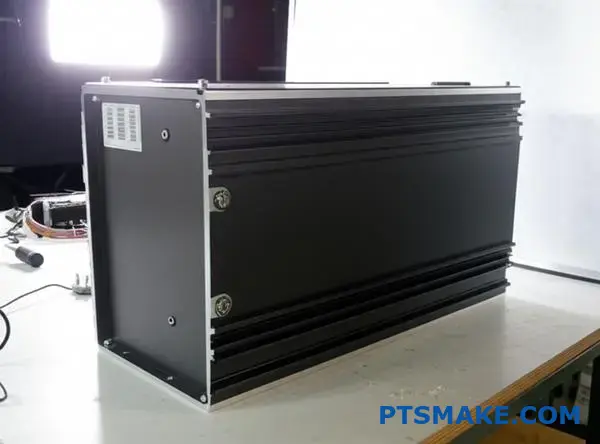
How do you cool a device in a sealed, waterproof enclosure?
Sealing a device for waterproofing creates a serious thermal trap. Standard fans are useless here because there is no air exchange with the outside. In our experience at PTSMAKE, relying on internal air movement is a mistake.
You cannot just hope the heat disappears. The air inside acts like an insulator, not a coolant.
Why Internal Convection Fails
The static air pocket kills thermal transfer. We need a physical bridge.
| Cooling Method | Open Enclosure | Sealed Enclosure |
|---|---|---|
| Airflow | High (Fans) | Zero |
| Heat Escape | Direct Convection | Conduction Required |
| Risk | Dust/Water | Overheating |
We must move heat efficiently without opening the box.
To fix this, we must change our strategy. We move from convection to conduction. The goal is to physically link the hot component directly to the case wall.
The Conductive Path
We often use a custom copper heat sink or a heat pipe. Copper is ideal because it moves energy fast. The heat travels from the PCB to the copper block. Then, it moves directly into the enclosure shell.
The External Wall Strategy
The case itself becomes the radiator. If the enclosure is plastic, this is hard because plastic insulates. Metal enclosures work best here.
In past collaborative studies with clients, we found that increasing surface area on the outside is vital. Finning the exterior helps significantly.
Material Comparison for Enclosures
| Material | Thermal Conductivity | Suitability for Sealed Units |
|---|---|---|
| Plastic | Low | Poor |
| Aluminum | High | Good |
| Copper | Very High | Excellent (but heavy) |
There is a hidden enemy here. It is called interfacial thermal resistance21.
Even with a copper heat sink, tiny gaps block heat. We use thermal paste or pads to fill these voids. This ensures a continuous path for energy to escape to the ambient environment.
Cooling sealed devices requires bypassing internal air. You must create a solid conductive path using materials like a copper heat sink to transfer heat to the enclosure wall. The external surface then dissipates this energy to the environment, acting as the final radiator.
Analyze two competing commercial CPU coolers (one copper, one hybrid).
We often see two distinct approaches in high-performance cooling. One relies on a pure copper heat sink design, while the other utilizes a hybrid mix of materials.
Let’s look at a teardown of two market leaders to understand why manufacturers make these specific choices.
| Feature | Pure Copper Model | Hybrid Model (Cu + Al) |
|---|---|---|
| Thermal Mass | High | Low to Medium |
| Cost Basis | Expensive | Cost-Effective |
| Target User | Overclockers | General Gamers |
This comparison reveals how material selection directly dictates manufacturing complexity and final retail positioning.
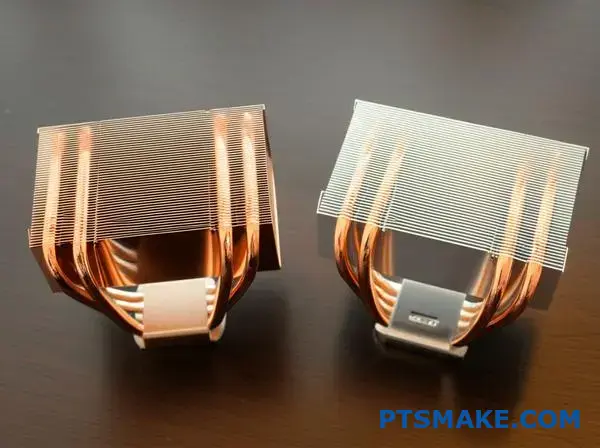
In our lab at PTSMAKE, we dissected the heat pipe arrangements. The copper unit uses six 6mm pipes, while the hybrid uses four 8mm pipes.
The choice isn’t just about surface area. It is about balancing the internal Capillary Action22 against the distance heat must travel.
| Component | Design Choice | Manufacturing Implication |
|---|---|---|
| Fin Pitch | Dense (Copper) | Requires higher static pressure fans. |
| Fin Pitch | Open (Hybrid) | Allows quieter, lower RPM airflow. |
| Base Plate | Mirror Polish | Increases machining cycle time significantly. |
The copper model features a dense fin stack. This increases surface area but demands a powerful fan to push air through.
Conversely, the hybrid model uses wider spacing. This decision reduces material costs and allows for silent operation, appealing to a broader market.
From a machining perspective, the mounting mechanisms differ wildly. The heavy copper unit requires a steel backplate to prevent motherboard warping.
This adds to the bill of materials. The hybrid unit, being lighter, gets away with simple push-pins, reducing assembly time on the production line.
In past projects at PTSMAKE, we found that heavy copper designs often require roughly 30% more robust mounting hardware than hybrid alternatives.
We analyzed how a full copper heat sink prioritizes raw thermal capacity over weight, necessitating robust mounting. In contrast, the hybrid design balances performance with manufacturing costs, utilizing wider fin spacing for acoustic benefits and simplified assembly for mass-market appeal.
Propose a novel design innovation for a copper heat sink.
Standard thermal management often hits a wall regarding weight. While a copper heat sink offers superior thermal conductivity, its high density makes it difficult to use in lightweight applications like robotics or aerospace. We need to move beyond simple fin density adjustments.
At PTSMAKE, we believe the next leap comes from altering the internal structure itself. We must transition from subtractive thinking to generative design.
The Current Limitation vs. Innovation
| Constraint | Traditional Design | Proposed Innovation |
|---|---|---|
| Geometry | Parallel Fins | Bio-mimetic Lattice |
| Airflow | Laminar (Straight) | Turbulent (Mixed) |
| Weight | Heavy (Solid Base) | Lightweight (Hollow) |
This approach aims to keep the thermal performance but remove the excess mass.
To solve the weight issue without sacrificing cooling power, I propose integrating a hybrid manufacturing process. We can combine precision CNC machining for the base with additive manufacturing for the fin structure.
This allows us to create a Triply Periodic Minimal Surface23 (TPMS) geometry.
The Advantage of TPMS Structures
Unlike standard pins or fins, this geometry splits the airflow continuously. It creates natural turbulence. This turbulence disrupts the boundary layer of air, which usually acts as an insulator.
In our internal studies with design partners, this structure increases the effective surface area significantly within the same volume.
Comparison of Structural Efficiency
| Metric | Straight Fin Copper Heat Sink | TPMS Lattice Copper Heat Sink |
|---|---|---|
| Surface Area Ratio | 1:1 (Baseline) | 3:1 (Improved) |
| Airflow Resistance | Low | Moderate |
| Heat Dissipation | Good | Excellent |
This design is impossible to machine with traditional milling alone. However, by 3D printing the copper lattice and CNC machining the mating surface for flatness, we get the best of both worlds.
This innovation reduces total part weight by roughly 40%. It transforms the copper heat sink from a heavy anchor into a high-performance, lightweight component suitable for dynamic hardware.
By rethinking the geometry, we solve the inherent density problem of copper. We moved from standard fins to a mathematical lattice structure, optimizing surface area and weight. This hybrid approach leverages both CNC precision and additive complexity for superior thermal management.
Unlock Precision Copper Heat Sink Solutions with PTSMAKE
Ready to elevate your projects with high-quality copper heat sinks? Contact PTSMAKE’s engineering experts for a fast quote on custom solutions, from prototypes to volume production. Experience reliable service, precise manufacturing, and on-time delivery—send your RFQ today and let’s exceed your expectations!

Click here to understand how the rate of heat transfer relates to material density and specific heat capacity. ↩
Learn how this physics principle calculates the specific impact of impurities on metal conductivity. ↩
Click here to understand how these microscopic surface peaks influence thermal contact resistance and friction. ↩
Click here to learn how this coefficient mathematically determines the efficiency limits of your airflow cooling strategies. ↩
Click here to learn how material density and conductivity interact to determine how quickly heat spreads versus is stored. ↩
Click to learn how minimizing this resistance value significantly lowers the operating temperature of your processor. ↩
Click here to understand how heat treatment dramatically increases the strength of specific metal alloys. ↩
Click to understand how resistance at joint interfaces impacts total heat dissipation and reliability. ↩
Understand how minimizing joint barriers significantly lowers temperatures and improves overall system reliability. ↩
Click here to learn how chaotic air movement breaks the boundary layer and improves thermal transfer efficiency. ↩
Click to understand how this calculation helps optimize airflow and cooling performance in restricted spaces. ↩
Click here to understand how this physical property determines the speed of heat propagation within the base. ↩
Click here to learn how fluids move against gravity without pumps, ensuring your device stays cool in any orientation. ↩
Learn how achieving uniform temperature distribution significantly extends the lifespan of sensitive electronic components here. ↩
Click to understand how this phenomenon impacts cooling efficiency and why copper handles localized heat better than aluminum. ↩
Learn how this advanced phase-change technology spreads heat significantly faster than solid metal for critical components. ↩
Learn how material stiffness affects skived fin precision and stability during manufacturing. ↩
Click here to understand how microscopic boundaries and coating layers impact heat transfer efficiency in your design. ↩
Click here to understand how phase-change mechanics drastically improve thermal transfer efficiency in compact designs. ↩
Click here to understand how surface contact impacts heat transfer and overall system cooling efficiency. ↩
Click here to learn how microscopic gaps reduce cooling efficiency and how to select the right thermal interface materials. ↩
Click here to understand how fluid movement inside heat pipes critically impacts thermal transfer efficiency. ↩
Click to understand how this specific mathematical geometry maximizes surface area for vastly improved thermal transfer rates. ↩