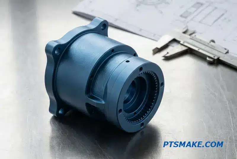
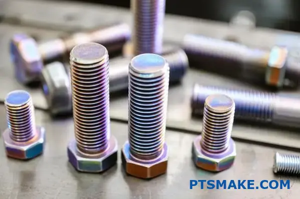
Finding the right cold heading partner for your precision fastener manufacturing can feel like searching for a needle in a haystack. You need consistent quality, reliable delivery, and technical expertise – but many suppliers fall short on critical specifications or communication when your production timeline is tight.
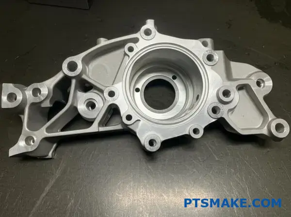
Cold heading is a precision metal forming process that shapes wire or rod material into complex fasteners and components using high-pressure dies, delivering superior strength and material efficiency compared to traditional machining methods.
After working with manufacturers across automotive, aerospace, and electronics industries, I’ve seen how the right cold heading expertise can transform your production efficiency. This comprehensive guide addresses the 16 most critical questions about cold heading processes, materials, and optimization strategies that directly impact your manufacturing success.
Why are certain materials ideal for cold heading?
Not all metals are suited for cold heading. Success depends entirely on choosing a material with the right properties.
These properties ensure the metal flows smoothly into the die under extreme pressure, all without fracturing. It’s the foundation of a reliable part.
The Essential Trio
Three properties are non-negotiable for this process:
Ductility and Malleability
Ductility allows the metal to be stretched. Malleability allows it to be shaped. Both are vital to avoid cracks.
Low Strain-Hardening
This ensures the material doesn’t become brittle too quickly during formation.
Here is a quick comparison:
| Property | Ideal for Cold Heading | Poor for Cold Heading |
|---|---|---|
| Ductility | High | Low |
| Malleability | High | Low |
| Strain-Hardening | Low Rate | High Rate |
Let’s explore this further. When a material hardens too quickly, it creates massive problems. The process demands more force, which accelerates tool wear and can ultimately cause part failure.
In past projects at PTSMAKE, we’ve seen how a high strain-hardening rate can stop a production run. It’s a critical factor to control.
Why Strain-Hardening Rate is Crucial
A low strain-hardening exponent means the material stays workable. It remains formable even as it’s being shaped into a complex geometry.
This allows the material to completely fill the die cavity. The internal grain structure1 of the metal is directly related to this behavior. A uniform, fine grain structure typically performs better.
Purity Makes a Difference
Material consistency is just as important. Small impurities or variations in the alloy can create weak spots. These spots are where fractures are most likely to occur.
This is why sourcing high-quality, certified raw materials is a cornerstone of our process. It guarantees predictable results.
| Material | Key Advantage | Common Application |
|---|---|---|
| Low-Carbon Steel | Excellent formability, cost-effective | Standard fasteners, screws |
| Stainless Steel (300 Series) | Corrosion resistance, good ductility | Medical and automotive parts |
| Aluminum Alloys | Lightweight, good strength-to-weight | Aerospace and electronic components |
| Copper Alloys | High conductivity, excellent malleability | Electrical connectors, rivets |
In short, successful cold heading relies on materials with high ductility and malleability. A low strain-hardening rate is equally essential to ensure the metal flows correctly into the die without fracturing during the high-pressure forming process.
What problem does cold heading solve better than machining?
When we choose a manufacturing process, we focus on its core advantages. Cold heading shines in three specific areas. It is a "chipless" method. This means almost no material is wasted.
Unlike machining, which cuts away material, cold heading reshapes it. This leads to significant cost savings on raw materials.
Production speed is another major win. Parts are formed very quickly. This is much faster than most traditional cutting methods. Let’s compare the material usage.
| Process | Material Usage | Waste |
|---|---|---|
| Cold Heading | Reshapes metal | < 5% |
| Machining | Cuts metal | 30% – 70% |
This efficiency translates directly into lower costs per part. It also enables much faster delivery times for high-volume orders.
Unpacking the Core Advantages
Let’s dig deeper into why these benefits are critical for your projects.
The Power of Chipless Manufacturing
Machining creates chips. That is expensive material you paid for and then threw away. With cold heading, that same material is simply moved into a new shape.
This near-zero waste is a game-changer for high-volume production. It drastically reduces your raw material costs over the life of a project.
Speed That Scales
Cold heading machines can produce hundreds of parts per minute. This level of speed is unmatched by most CNC centers for suitable part geometries.
This advantage significantly cuts down lead times. It also lowers the cost per piece, making it an ideal choice for large-scale production.
Strength Through Formation
The process itself makes the part stronger. It is not just about shaping the metal.
The material undergoes work hardening, which increases its tensile strength. The continuous, unbroken grain flow2 along the part’s contours adds fatigue resistance. This is a structural benefit you cannot achieve by cutting material.
Let’s compare the structural impact.
| Feature | Cold Heading | Machining |
|---|---|---|
| Grain Structure | Unbroken, follows contour | Severed at surfaces |
| Work Hardening | Yes, increases strength | No, removes material |
| Fatigue Resistance | Excellent | Good, but susceptible |
This inherent strength means parts can often be designed with less material. In our projects at PTSMAKE, we help clients leverage this for further cost savings.
In short, cold heading offers a powerful combination of benefits. It minimizes material waste, accelerates production dramatically, and enhances the part’s mechanical strength through the forming process itself. This makes it a superior choice for specific applications.
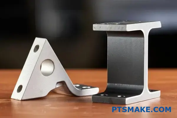
What fundamentally limits the complexity of a cold-headed part?
Physical laws are the ultimate rulebook for cold heading. We can’t just create any shape we want. The material itself is the first major constraint.
Material Formability
Not all metals are created equal. Some are more willing to be shaped than others. This property is called formability.
Softer materials like aluminum or copper are easier to work with. Harder alloys, like certain steels, resist deformation. Pushing them too far can cause cracks.
| Material | Relative Formability | Common Issues |
|---|---|---|
| Low-Carbon Steel | Good | Work hardens quickly |
| Aluminum Alloys | Excellent | Can be too soft for some tools |
| Copper | Excellent | Lower strength |
| Stainless Steel | Fair to Poor | High forming pressures required |
Choosing the right material is a critical first step in the design process.
The Upset Ratio Rule
In cold heading, we can only gather a certain amount of material in a single step, or "station." This is governed by the upset ratio. Think of it as a speed limit for forming.
Typically, you can’t form a head with a diameter more than about 2.5 times the wire’s original diameter in one hit. Trying to exceed this leads to bending or defects.
For more complex parts with larger heads, we must use multiple stations. Each station progressively shapes the part. This multi-step process allows for greater complexity. It prevents the material from becoming over-stressed.
Internal and Tooling Constraints
Beyond the material itself, the process has its own limits. The extreme pressures can cause internal flaws if not managed properly. This is where experience at PTSMAKE becomes vital.
Tooling design is another critical factor. The punches and dies that shape the part must withstand immense force repeatedly. Their geometry limits the features we can create. For example, creating sharp internal corners is nearly impossible. This is because the tooling required would be too fragile. The process of work hardening3 also applies to the material as it’s being formed, increasing the force required in subsequent steps.
| Constraint | Description | Impact on Complexity |
|---|---|---|
| Tooling Strength | Dies must resist cracking under pressure. | Limits sharp features and thin walls. |
| Tooling Access | Tools need space to enter and exit. | Restricts deep cavities and undercuts. |
| Ejection | Part must be removable from the die. | Limits non-tapered internal shapes. |
Physical limits, from material formability and upset ratios to tooling strength, dictate complexity. Understanding these constraints is key for successful design. This knowledge helps prevent defects and ensures the integrity of every cold-headed part we produce.
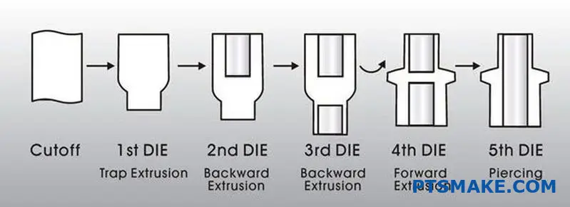
What are the different types of forming operations?
Cold heading isn’t a single action. It is a sequence of precise operations. These steps shape metal wire without heat.
This process combines four fundamental techniques. These are upsetting, extrusion, and trimming.
Each step has a specific function. Together, they create complex parts from simple wire. At PTSMAKE, we leverage this for high-speed, low-waste production.
| Operation | Primary Function |
|---|---|
| Upsetting | Gathers material to increase diameter. |
| Extrusion | Reduces diameter or creates a cavity. |
| Trimming | Creates the final head shape. |
A Closer Look at Cold Heading Operations
Understanding these core operations is key. It shows how a simple wire becomes a complex fastener. Mastering this process allows us to produce high-precision parts efficiently.
Upsetting: Gathering Material
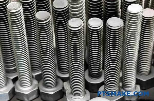
Upsetting is often the first step. It involves applying force to the end of the wire. This action makes the wire shorter and thicker, gathering material to form the head of a part like a screw or bolt.
Extrusion: Reshaping the Diameter
Extrusion changes the wire’s diameter. In forward extrusion, we push the wire through a smaller die. This lengthens a section while reducing its diameter. Backward extrusion pushes a punch into the wire, making material flow back around it to create a cavity. This is how we form the socket in a hex cap screw. The material’s grain structure is improved by this controlled deformation, which enhances its strength due to work hardening4.
| Extrusion Type | Process | Common Application |
|---|---|---|
| Forward Extrusion | Material flows in the direction of the punch force. | Creating stepped shafts or pins. |
| Backward Extrusion | Material flows opposite to the punch force. | Forming hollow parts or sockets. |
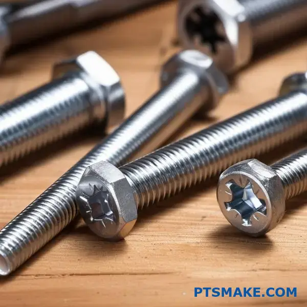
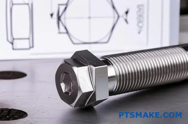
Trimming: Defining the Shape
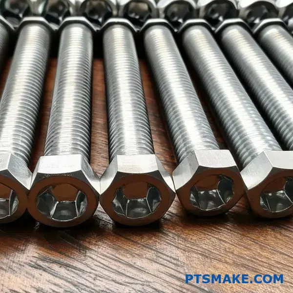
Trimming is the final shaping process. After upsetting creates a round head, trimming cuts away excess material. This creates specific shapes, like the hexagonal head on a standard bolt or a custom design for a client’s unique application.
Cold heading utilizes four key operations: upsetting, extrusion, and trimming. Each step manipulates the metal in a specific way. By combining these, complex geometries like bolts and custom fasteners are produced efficiently and with minimal material waste.
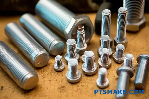
How are cold heading materials typically categorized for selection?
Choosing the right material is vital. It directly impacts your part’s performance, lifespan, and cost. At PTSMAKE, we guide clients through this critical decision daily.
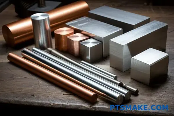
Materials are generally grouped into four main families. Each offers a unique blend of properties.
Primary Material Groups
We start by looking at these major categories. This helps narrow down the options based on core requirements for any cold heading project.
| Material Category | Relative Cost | Typical Strength | Corrosion Resistance |
|---|---|---|---|
| Low-Carbon Steels | Low | Medium | Low |
| Alloy Steels | Medium | High | Low-Medium |
| Stainless Steels | High | High | Excellent |
| Non-Ferrous Alloys | Varies | Low-Medium | Good-Excellent |
This initial breakdown provides a clear starting point.
Deeper Dive into Selection Criteria
Choosing a material is always a balancing act. You must weigh performance needs against budget constraints. No single material is perfect for every application.
Steels: The Versatile Choice
Low-carbon steels are the most common. They are cost-effective and easy to form. They’re great for general-use fasteners that don’t face harsh conditions.
Alloy steels are the next step up. Adding elements like chromium or molybdenum increases strength. This makes them ideal for high-stress parts in automotive or machinery. They often require a protective coating.
Stainless steels offer the best corrosion resistance. This is non-negotiable for medical, marine, or food-grade applications. However, they are more expensive and can be tougher to form. The process itself increases material hardness through work hardening5.
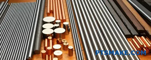
Non-Ferrous Alloys: Specialized Solutions
Non-ferrous materials solve specific problems. We use aluminum for lightweight aerospace parts. Copper is chosen for its excellent electrical conductivity. Brass offers good corrosion resistance and a unique appearance.
In our experience, these are chosen when a specific property, not achievable with steel, is the primary driver.
| Material Example | Typical Industry | Key Selection Driver |
|---|---|---|
| Carbon Steel 1022 | Construction | Lowest Cost |
| Alloy Steel 4037 | Automotive | High Tensile Strength |
| Stainless Steel 316 | Marine | Superior Corrosion Resistance |
| Aluminum 6061 | Aerospace | Lightweight |
This decision process ensures the final part meets all specifications perfectly.
Selecting the right material involves a trade-off. You must balance cost, strength, and environmental resistance. Each category presents a unique profile, making careful evaluation key for optimal performance and project success.
What are the common secondary operations after cold heading?
After cold heading forms the basic shape, the part is often unfinished. It still needs key features to function correctly.
Secondary operations add these final touches. This includes creating threads for fastening. It also involves treatments for strength and protection.
These steps are crucial for performance. They turn a basic blank into a high-quality, reliable component ready for assembly.
| Operation | Primary Purpose |
|---|---|
| Thread Rolling | Forms external screw threads. |
| Heat Treating | Enhances mechanical properties. |
| Plating | Adds corrosion resistance and finish. |
| Sealant Patches | Provides locking or sealing. |
These operations are performed separately for good reason. Each requires specialized machinery and expertise that differ from the initial forming process.
Thread Rolling
This process forms threads by pressing and rolling a die into the part. Unlike cutting, it displaces metal, not removes it. This creates stronger, more durable threads. It’s a precise mechanical step after the initial shape is made.
Heat Treating
Heat treatment changes the part’s physical properties. Processes like quenching6 and tempering increase hardness and tensile strength. This thermal process is done in furnaces, entirely separate from the cold heading machines.
In our experience at PTSMAKE, a proper heat treatment can increase part longevity significantly.
| Property | Before Heat Treat | After Heat Treat |
|---|---|---|
| Hardness (HRC) | ~20 | 40-50+ |
| Tensile Strength | Lower | Significantly Higher |
| Wear Resistance | Standard | Excellent |
Plating and Finishing
Plating adds a protective layer. Zinc or chrome coatings prevent corrosion and improve appearance. This is a chemical or electrochemical process. It requires a completely different environment and skill set than mechanical forming.
Sealant and Adhesive Patches
For fasteners needing extra security, pre-applied sealant patches are added. These patches activate during installation to prevent loosening from vibration. This application is a final, precise step before packaging.
Cold heading creates the part’s fundamental geometry. However, crucial secondary operations like thread rolling, heat treating, and plating are essential. These separate steps add the final strength, features, and protective finishes required for real-world performance.
What industry standards govern cold heading materials and products?
Navigating the world of cold heading requires a map. Industry standards are that map. They ensure every part meets specific quality and performance benchmarks.
Key organizations provide this guidance. The most important ones are IFI, ASTM, and ISO. Each has a unique focus.
Key Standards Bodies
These groups establish the rules for materials, dimensions, and testing. Adhering to them is non-negotiable for reliable manufacturing.
| Organization | Primary Focus |
|---|---|
| IFI | Fastener-specific standards, engineering data. |
| ASTM | Material specifications, testing methods. |
| ISO | International standards for global compatibility. |
These standards are not just documents. They are detailed blueprints for production. They dictate the essential characteristics of every cold headed part.
This adherence ensures that a screw made today matches one made next year. This consistency is vital for our clients’ assembly lines and product reliability.
How Standards Shape the Final Product
Standards like ASTM A29 define the exact chemical makeup of steel wire. They control elements like carbon and manganese.
This ensures the material can be formed correctly and will perform as expected. Certain materials may require annealing7 to achieve the right ductility before the cold heading process.
Dimensional and Mechanical Control
Standards also set the rules for a part’s final properties. In our work at PTSMAKE, we rely on these to guarantee performance. They remove any guesswork from manufacturing.
| Standard Type | Governed Properties | Example Standard |
|---|---|---|
| Dimensional | Thread size, head height, length. | IFI 7th Edition |
| Mechanical | Tensile strength, proof load, hardness. | ISO 898-1 |
Following these precise guidelines is crucial. It ensures every component is dependable, safe, and fits perfectly into its final application. This is a promise we make to every client.
In short, standards from IFI, ASTM, and ISO are essential. They govern materials, dimensions, and mechanical properties. This framework ensures every cold headed product is reliable, consistent, and fit for purpose.
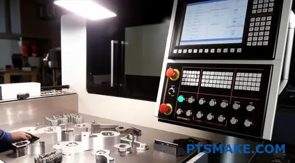
How do you adjust machine settings to control part dimensions?
Mastering dimensional control isn’t magic. It’s a science of cause and effect. Each setting adjustment directly impacts a specific feature of the part.
Understanding these relationships is key. It turns guesswork into a precise, repeatable process. This is fundamental in manufacturing.
Core Adjustment-Dimension Links
| Machine Setting | Affected Dimension | Primary Impact |
|---|---|---|
| Wire Stop | Overall Length | Controls material cutoff volume |
| Knockout Pin | Head Diameter/Shape | Ejects the part; timing is crucial |
| Die/Punch Alignment | Concentricity | Ensures uniform pressure on material |
A Deeper Look at Cause and Effect
In my experience, small adjustments can yield significant changes. Let’s break down why these settings are so critical for precision. It’s about controlling how the material behaves under immense pressure.
Wire Stop and Its Impact on Length
The wire stop physically blocks the wire feed. This determines the volume of material for the next part. If you move it back, you get more material and a longer part. If you move it forward, you get less. It is a direct one-to-one relationship.
Knockout Pin Timing and Head Formation
The knockout pin ejects the finished part from the die. If its timing is too early or too late, it can affect the head. Poor timing can cause deformation or material smear on the part’s face. This is especially true in multi-blow cold heading operations. The material undergoes significant plastic deformation8 to form the head.
Die and Punch Alignment for Concentricity
This is non-negotiable for quality. If the punch and die are not perfectly aligned, the force applied is uneven. This imbalance causes the material to flow inconsistently, resulting in a part where the head is off-center from the shank.
| Problem | Likely Cause | Corrective Adjustment |
|---|---|---|
| Part too long | Wire stop is too far back | Move wire stop forward |
| Deformed head | Incorrect knockout pin timing | Adjust knockout pin timing |
| Poor concentricity | Misaligned die and punch | Re-align tooling carefully |
Controlling dimensions is about understanding the direct link between a setting and its result. Adjusting the wire stop, knockout pin, and tool alignment provides precise, predictable control over the final part, ensuring it meets every specification perfectly.
How do you calculate the production cost for a cold-headed part?
Calculating the final price for a cold-headed part is not guesswork. It’s a clear formula. You simply add up a few key costs.
This approach ensures transparency. It also helps you understand where your money is going. Every factor has its place in the final calculation.
The Core Cost Formula
The final piece price is the sum of several distinct components. Understanding each one is key to optimizing your budget for any cold heading project.
| Cost Component | Description |
|---|---|
| Raw Material | Cost of the wire used for the part. |
| Machine Run Time | Hourly cost to operate the forming machine. |
| Tooling Amortization | The tooling cost spread across all parts. |
| Labor | Cost for setup, operation, and inspection. |
| Secondary Operations | Any post-forming processes like plating. |
Breaking Down Each Cost Component
To get an accurate quote, we must look closer at each part of the formula. Each component has its own variables that influence the total cost. At PTSMAKE, we break this down clearly for our partners.
Raw Material (Wire)
This is more than just the material type. We calculate the exact weight of material per part. Then, we add a factor for scrap, which is the small amount of material lost during the process. Material choice is a major cost driver here.
Machine and Labor Costs
The hourly rate of a cold heading machine depends on its size and capability. A larger, more complex machine costs more to run. We pair this with the cycle time. Faster cycles mean lower machine cost per piece. Labor for setup and quality checks is also factored in.
Tooling and Secondary Operations
Tooling Amortization9 is a critical factor. The upfront cost of the die and punch set is divided by the total number of parts in the production run. For larger volumes, this cost per piece becomes very small. Finally, we add costs for any secondary steps. This includes heat treating, plating, or thread rolling.
Here is the simple formula we use:
| Formula Component | Symbol |
|---|---|
| Raw Material Cost per Piece | A |
| Machine Run Time Cost per Piece | B |
| Tooling Amortization per Piece | C |
| Labor Cost per Piece | D |
| Secondary Operations Cost per Piece | E |
| Final Price per Piece | A+B+C+D+E |
Understanding this formula is crucial. The total cost of a cold-headed part is the sum of raw materials, machine time, tooling, labor, and any extra processing. This clear breakdown helps you make smart decisions and find cost-saving opportunities for your project.
How would you plan the forming sequence for a non-symmetrical part?
Let’s apply our methodology to a complex part. Imagine a component with an off-center head and a sideways protrusion. This isn’t straightforward. You can’t just hit it once.
The Real-World Challenge
Planning for such parts is a puzzle. The goal is to move metal where you need it without causing defects. It requires a step-by-step approach. Each stage prepares the material for the next. This careful planning is key in processes like cold heading.
Initial Forming Considerations
We start by gathering the material. The initial blows create a basic, slightly asymmetrical shape. This sets the foundation for the more complex features that will follow.
| Feature | Symmetrical Part | Non-Symmetrical Part |
|---|---|---|
| Material Flow | Evenly distributed | Needs careful direction |
| Tool Forces | Balanced | Unbalanced, requires compensation |
| Part Transfer | Simple rotation | Requires precise orientation |
Advanced Techniques for Complex Geometries
For truly complex parts, we need advanced strategies. Simply pushing material isn’t enough. We must guide it with precision. This is where specialized tooling comes into play. It’s about outsmarting the material’s natural tendency to flow to the path of least resistance.
Using Traps and Shaped Punches
To manage the metal, we use features like traps or shaped punches. A trap is a cavity in the die that "catches" excess material. This prevents it from flowing into unwanted areas. A shaped punch actively directs the metal. It forces it into the precise asymmetrical features we need. This level of Material Flow Control10 is crucial.
Ensuring Correct Orientation
When the part moves from one station to the next, its orientation is critical. A part that is even slightly rotated will be formed incorrectly. In past projects at PTSMAKE, we have used features on the part itself, like a small flat or D-shape, to act as a key. The transfer mechanism grips this feature, ensuring perfect alignment every time.
Balancing Forces to Prevent Shifting
An unbalanced shape creates unbalanced forces. This pressure can cause the die or punch to shift slightly during the forming blow. This leads to dimensional errors. We counteract this by designing the tooling to balance these forces, often by adding counter-pressures or support features within the die set.
| Problem | Solution | Tooling Example |
|---|---|---|
| Uneven Fill | Shaped Punches | Punches with angled or curved faces |
| Part Misalignment | Orientation Features | D-shaped punch, keyed transfer fingers |
| Tool Shift | Force Balancing | Opposing pressure pads, robust die lock |
Applying these techniques requires a deep understanding of material behavior. For complex non-symmetrical parts, this careful, deliberate approach transforms a difficult challenge into a repeatable, high-quality manufacturing process. It’s how we deliver the precision our partners expect.
Mastering complex non-symmetrical parts requires advanced techniques. By using traps, shaped punches, and ensuring correct orientation, we precisely control material flow. Balancing forces is also critical to prevent tool shifting and maintain accuracy throughout the process.
A part shows chevron cracks. How do you troubleshoot this?
Let’s dive into a specific case. The chevron cracks appear after a cold heading extrusion step. Our first task is to isolate this exact operation.
Identifying the Root Cause
We need to pinpoint which extrusion is the culprit. Once found, we focus on three key variables. These are the process parameters that directly influence internal material stress.
Key Adjustment Parameters
Analyzing these factors methodically is crucial. Adjusting them correctly will resolve the cracking issue.
| Parameter | Primary Influence |
|---|---|
| Extrusion Angle | Material Flow & Friction |
| Back Pressure | Internal Tensile Stress |
| Material Coating | Surface Friction |
This structured approach helps us find a solution quickly.
![]()
A Step-by-Step Analysis
Troubleshooting chevron cracks requires a systematic approach. We can’t just guess. At PTSMAKE, we break down the problem into manageable parts.
Adjusting the Extrusion Angle
The die’s extrusion angle is critical. A very large angle can cause excessive material deformation. This creates high tensile stresses at the part’s center.
Conversely, a very small angle increases friction. It can also create dead zones where material doesn’t flow smoothly. Our goal is to find the optimal angle.
Calibrating Back Pressure
Insufficient back pressure is a frequent cause. Without enough counter-pressure, the material is pulled apart internally. This happens as it’s forced through the die.
Proper back pressure induces a compressive hydrostatic pressure11 state. This state counteracts the tensile forces that lead to chevron cracks.
Evaluating Material Coating
Never overlook the material coating. Proper lubrication is essential in any cold heading process. It reduces friction between the workpiece and the die.
If the coating is thin, inconsistent, or the wrong type, friction spikes. This adds to the tensile stress. We always verify the coating process first.
| Problem Symptom | Potential Adjustment | Expected Outcome |
|---|---|---|
| Cracks at center | Increase back pressure | Reduce internal tension |
| High friction signs | Improve material coating | Smoother material flow |
| Poor material flow | Optimize extrusion angle | Balanced deformation |
Executing this advanced troubleshooting requires precision and experience. It’s about controlling internal stresses.
Troubleshooting chevron cracks involves isolating the specific extrusion operation. Then, you must systematically analyze and adjust the extrusion angle, back pressure, and material coating to eliminate the root cause of the internal material failure.
How do you evaluate switching to a lower-cost material?
Switching materials is more than a line item change. A lower price is tempting, but a full evaluation is crucial. You must create a detailed validation plan.
This plan prevents future production headaches. It ensures the new material truly delivers value without compromising quality.
The Validation Blueprint
A solid plan is your roadmap. It should outline every test and trial required before you make a final decision. This systematic approach identifies risks early.
Key Validation Stages
We break our validation process into three core stages. Each stage addresses a different aspect of the manufacturing process and final part quality.
| Stage | Focus Area | Key Objective |
|---|---|---|
| 1 | Formability Trials | Assess how the material behaves during manufacturing. |
| 2 | Tooling Assessment | Measure the impact on tooling wear and lifespan. |
| 3 | Final Part Testing | Verify all mechanical and performance specifications. |
Analyzing the Complex Trade-offs
The initial cost saving is often just the tip of the iceberg. True evaluation requires looking deeper at the hidden costs and potential performance issues that can arise.
In past PTSMAKE projects, we’ve seen seemingly minor material changes cause major disruptions downstream. A comprehensive plan is your best defense against this.
Uncovering Hidden Risks
Your validation plan must be designed to uncover these complex trade-offs. It’s about balancing cost savings against potential long-term expenses and performance risks.
Formability and Its Impact
How well does the new material form? Poor formability can lead to higher scrap rates or require slower cycle times, eating into your savings. This is critical for processes like cold heading where material flow is everything.
In our tests, some low-cost alloys required a 15% reduction in production speed to prevent defects.
The Long-Term Cost of Tooling
Cheaper material can sometimes be more abrasive. This leads to faster tooling wear. The new material might cause higher levels of Abrasive Wear12, increasing maintenance costs.
You must track tooling wear rates carefully during trial runs.
| Material | Tooling Lifespan (Cycles) | Notes |
|---|---|---|
| Standard Steel | 500,000 | Predictable wear |
| Low-Cost Alt. | 350,000 | 30% faster wear rate |
Final Performance is Non-Negotiable
The final part must meet every single specification. This includes mechanical strength, corrosion resistance, and thermal stability. Comprehensive testing is the only way to confirm this. No compromises are acceptable on final part performance.
A validation plan isn’t just a checklist. It’s a critical process to assess formability, tooling impact, and final part performance, ensuring that a lower-cost material doesn’t introduce hidden expenses or product failures down the line.
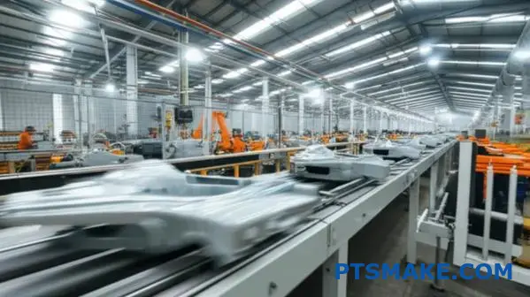
How would you optimize a process to increase production by 15%?
Finding the slowest part of your production line is key. This bottleneck controls your entire output. Simply speeding up other steps won’t help. You must focus on the real constraint.
Uncovering Production Bottlenecks
In my experience, bottlenecks are often hidden in plain sight. They can be a machine, a process, or even a person.
Key Areas to Investigate
- Machine Speed and Uptime
- Changeover Times
- Tool and Equipment Maintenance
Here’s a simple look at the impact of fixing them.
| Metric | Before Optimization | After Optimization |
|---|---|---|
| Units Per Hour | 85 | 100 |
| Daily Downtime | 60 mins | 15 mins |
| Changeover Time | 45 mins | 10 mins |
Resolving these issues is the fastest path to a significant gain.
To truly optimize, we must dig deeper than just observing. We need to measure everything. This data-driven approach removes guesswork. It pinpoints the exact cause of the delay, which is a core principle we follow at PTSMAKE.
Analyzing Machine Performance
Don’t just accept the manufacturer’s speed settings. Are you running the machine at its true optimal speed for your specific material and part? Sometimes a small adjustment, confirmed through testing, makes a huge difference.
The SMED Approach to Changeovers
Reducing changeover time is critical. The principles of Single-Minute Exchange of Die (SMED) are transformative. We separate internal setup (done when the machine is stopped) from external setup (done while running).
| Changeover Step | Traditional Method | SMED Method |
|---|---|---|
| Prep Tools | During downtime | During production |
| Find Molds | During downtime | Pre-staged |
| First Part Check | Machine stopped | Minimized downtime |
This systematic approach can cut changeover times dramatically.
Extending Tool Life
Downtime from worn or broken tools is a silent killer of productivity. Proper tool management, including using higher-quality materials and predictive maintenance schedules, is non-negotiable. This is especially true for demanding processes like cold heading. Following the Theory of Constraints13 helps prioritize these improvements effectively.
In short, achieving a 15% production increase isn’t about magic. It’s about a systematic process. Identify your specific bottlenecks, apply proven methods, and manage your tools effectively. This targeted approach delivers real, measurable results.
A customer requests a quote for a complex new fastener. How do you determine feasibility?
When a complex fastener print lands on my desk, the process is methodical. It’s not just about quoting a price. It’s about ensuring we can deliver.
The first step is a deep dive into the technical drawing. We analyze every detail.
Initial Print Review
We meticulously check dimensions, tolerances, and material specs. This initial review helps us understand the part’s core requirements. It forms the basis for all subsequent decisions.
| Review Area | Key Focus |
|---|---|
| Dimensions | Overall length, head diameter, thread specs |
| Tolerances | Critical feature tightness, geometric constraints |
| Material | Grade, heat treatment, required finish |
| Features | Complex head shapes, secondary operations |
This analysis determines if the part is even a candidate for our processes.
Engineering and Tooling Collaboration
After the initial review, we move to the core engineering assessment. This is where we calculate the real feasibility. We must determine if the fastener can be formed.
Volume and Ratio Calculations
We calculate the volume of material needed for each forming station. This is critical for processes like cold heading. A key metric is the upset ratio14, which tells us how much material we must gather to form the head.
If the ratios are too high, the material may crack during forming. This is a major red flag we identify early. In past projects at PTSMAKE, this calculation has saved significant time and resources.
Identifying High-Risk Steps
We map out the entire forming sequence, station by station. Each step is analyzed for potential problems.
| Forming Step | Potential Risk | Mitigation Strategy |
|---|---|---|
| First Blow | Incomplete fill of the die | Adjust wire cutoff length |
| Head Upset | Cracking due to high upset ratio | Add an intermediate forming station |
| Extrusion | Poor surface finish | Optimize tooling design and lubrication |
| Trimming | Burr formation | Sharpen or redesign trim dies |
Consulting Tooling Experts
Finally, I bring these findings to our tooling designers. Their hands-on experience is invaluable. They confirm if the tooling can be built to handle the high-risk steps reliably and economically. This collaboration ensures our quote is not just a number, but a commitment to success.
Our feasibility process is a blend of careful calculation and expert collaboration. We review the print, analyze forming ratios, identify risks, and consult with toolmakers. This ensures we provide an accurate, reliable quote for even the most complex fasteners.
How can you use cold heading to minimize secondary machining?
The goal is to get as close to the final shape as possible. This is called near-net-shape manufacturing. It’s a core benefit of cold heading.
We achieve this by carefully planning each forming step. This thoughtful design is key.
Designing the Forming Sequence
A well-designed sequence can create complex features. This eliminates the need for later cutting or grinding. You save both time and material waste.
Consider these common features:
| Feature | Cold Heading | Secondary Machining |
|---|---|---|
| Points | Formed directly | Grinding required |
| Shoulders | Precise & strong | Cutting operation |
| Undercuts | Possible with design | Often needs complex tooling |
This approach makes production faster and more cost-effective.
Achieving Precision Without Cutting
The magic of cold heading is in the die and punch design. Each station in the machine performs a specific action. We map out the entire process before starting.
This isn’t just about shaping metal. It’s about controlling how the material moves.
Creating Complex Features Intelligently
At PTSMAKE, we focus on this planning phase. For instance, creating an undercut requires a multi-step sequence. The material is first gathered, then formed into the complex shape.
This controlled process also introduces beneficial work hardening15, strengthening the part. This is an advantage you don’t get from machining.
Designing these sequences is part art, part science. It relies on a deep understanding of material properties.
Forming Sequence Example
Here’s a simplified look at a sequence for a custom pin:
| Stage | Action | Result |
|---|---|---|
| 1. Cutoff | A precise length of wire is cut. | Blank is ready. |
| 2. First Hit | Material is gathered for the head. | Basic head shape forms. |
| 3. Second Hit | The head is fully formed. | Final head dimensions set. |
| 4. Extrusion | The shank diameter is reduced. | Shoulder and shank created. |
This method creates a finished part with minimal waste. It avoids costly and time-consuming secondary operations entirely.
By designing smart forming sequences for cold heading, we produce near-net-shape parts. This strategy significantly reduces the need for secondary machining, saving material, time, and costs while improving part strength.
How would you approach heading a difficult material like stainless steel?
Heading stainless steel requires a different mindset. You can’t apply standard methods and expect top results. Success comes from careful adjustments. This means slowing down the process.
Adapting Standard Practices
It’s about being methodical. We focus on three critical modifications to achieve a flawless cold heading process.
Key Areas of Focus
| Adjustment Area | Standard Approach | Stainless Steel Approach |
|---|---|---|
| Machine Speed | Maximum | Reduced |
| Lubrication | Standard oil | Specialized, high-pressure |
| Tool Geometry | Sharp radii | Larger, smoother radii |
These changes are not optional. They are essential for quality.
The primary reason stainless steel is tough to work with is its high work-hardening rate. The material gets stronger and harder very quickly as you form it. This puts incredible stress on both the machine and the tooling.
Slower Machine Speeds
Slowing down the machine is the first and most crucial step. A slower speed generates less heat during formation. This significantly reduces the work-hardening effect. It also gives lubricants more time to create a protective film, preventing tool failure.
Advanced Lubricants and Coatings
Standard lubricants simply can’t handle the pressure. We rely on specialized lubricants designed for high-pressure applications. These are critical for a smooth cold heading operation. Equally important are tool coatings. They prevent material from welding to the tool. The high strain hardening exponent16 of stainless steel makes these advanced solutions necessary.
Tool Coating Selection
| Coating | Primary Advantage | Application Notes |
|---|---|---|
| TiN (Titanium Nitride) | Good lubricity, wear resistance | Effective for less challenging stainless grades |
| AlCrN (Aluminum Chromium Nitride) | Superior heat and oxidation resistance | Our choice for high-strength, tough alloys |
Smarter Tooling Design
Finally, the tools themselves must be adapted. Sharp corners are a recipe for failure. We design heading tools with larger, more generous radii. This helps the stainless steel flow smoothly and evenly into the die cavity. This design choice reduces stress concentration and prevents cracking.
Adapting your process is crucial for stainless steel. This means using slower speeds, specialized lubricants, coatings like TiN or AlCrN, and tools with larger radii. These modifications are essential to manage the material’s high work-hardening rate and ensure a successful outcome.
Unlock Cold Heading Excellence with PTSMAKE Today
Ready to accelerate your manufacturing goals? Get a fast, precise quote on expert cold heading solutions from PTSMAKE. Our team specializes in high-precision B2B manufacturing—send us your requirements and discover why industry leaders trust us for quality, speed, and reliability. Inquire now!

Understand how a material’s internal atomic arrangement impacts its performance and formability in manufacturing processes. ↩
Learn how grain structure impacts part durability and why it’s a key advantage in metal forming processes. ↩
Click to understand how this property affects material strength and limits subsequent forming operations. ↩
Click to understand how this process strengthens metal without heat, a key benefit of cold forming. ↩
Learn how this metallurgical process improves strength during cold forming and impacts your design choices. ↩
Learn how this rapid cooling process is key to achieving desired material hardness. ↩
Learn how this heat treatment prepares metals for the intense pressures of the cold heading process. ↩
Understand the principles of plastic deformation to better predict material behavior during the cold heading process. ↩
Click to understand how tooling costs are spread and how it impacts your per-piece price. ↩
Explore detailed guides on controlling material behavior for better part quality and fewer defects. ↩
Learn how this compressive stress state prevents internal cracking during material forming. ↩
Understand how different material properties can impact your tooling lifespan and overall production costs. ↩
Discover how this powerful management philosophy can eliminate your most critical production constraints. ↩
Click to understand this key metric for fastener formability and its impact on manufacturing success. ↩
Learn how this metallurgical process increases the strength and durability of cold-headed parts. ↩
Understand how this value dictates a material’s response to forming. ↩