Many manufacturers struggle with gravity casting defects, inconsistent quality, and production delays that cost thousands in rework and missed deadlines. These issues often stem from poor understanding of the fundamental physics behind metal flow, inadequate material selection, and lack of systematic process control.
Gravity casting is a foundational metal forming process where molten metal flows into molds under gravitational force alone. Success depends on mastering fluid dynamics, heat transfer, and solidification physics to produce high-quality cast parts consistently.
Through my experience at PTSMAKE, I’ve worked with engineering teams who needed reliable casting solutions but faced the same recurring challenges. This guide covers the 16 essential questions that will help you master gravity casting fundamentals, troubleshoot common defects, and build robust production processes for your next project.
What is gravity casting’s core principle, beyond just pouring metal?
Gravity casting is often seen as simple. You just pour molten metal into a mold, right? But the real principle is a delicate balance of physics.
It’s about controlling how gravity works for you. The process relies on a trio of scientific principles working together.
The Physics at Play
Understanding these forces is key. They determine the final quality of the part.
| Principle | Role in Gravity Casting |
|---|---|
| Fluid Dynamics | Governs how metal flows into the mold. |
| Heat Transfer | Manages cooling and solidification rates. |
| Solidification | Dictates the final grain structure. |
These elements must be managed perfectly.
The core principle goes much deeper. It’s about using gravity to generate predictable and consistent force. This force dictates the flow and pressure inside the mold cavity.
How Gravity Dictates Flow
Gravity is the engine of the process. It pushes the molten metal into every detail of the mold. The height of the pouring sprue directly influences the metallostatic pressure1.
This pressure ensures the mold is filled completely. It helps create sharp details and avoid voids. A higher sprue means more pressure.
The Thermal Balancing Act
As the metal flows, it starts cooling. This heat transfer must be managed carefully. The mold design and material are critical here.
We design cooling channels to control the solidification rate. This prevents defects like cracks or porosity. It ensures the part solidifies uniformly, creating a strong internal structure.
In our work at PTSMAKE, we focus on this balance. Proper gating and riser design are essential. They are not just channels; they are tools to control flow and temperature.
| Factor | Influence on the Process |
|---|---|
| Pouring Temperature | Affects fluidity and cooling time. |
| Mold Temperature | Influences solidification speed and surface finish. |
| Gating System Design | Controls flow rate and turbulence. |
Mastering these factors is what separates a quality casting from a failure. It’s a science we’ve refined over many projects.
Gravity casting’s core isn’t just pouring. It’s a controlled application of physics. Mastering the interplay of fluid dynamics, heat transfer, and solidification is essential. Gravity provides the fundamental force that, when managed correctly, produces high-quality, reliable parts.
What key properties define a suitable gravity casting alloy?
Selecting the right alloy is crucial. The material’s behavior during casting directly impacts the final part’s quality. It’s not just about the end properties. It’s about how the metal flows, cools, and solidifies.
Fluidity: Filling the Mold
Fluidity is the alloy’s ability to fill intricate mold cavities. Poor fluidity leads to misruns and incomplete parts. This is a common failure point we design against.
Solidification & Shrinkage
As the metal cools, it shrinks. Understanding this is vital. A wide solidification range can cause porosity, while excessive shrinkage may lead to defects.
| Property | High Suitability | Low Suitability |
|---|---|---|
| Fluidity | Fills complex details easily | Incomplete fills, misruns |
| Shrinkage | Minimal and predictable | High risk of voids, cracks |
| Hot Tear Resistance | Strong during cooling | Prone to cracking |
When we dive deeper, the interplay between these properties becomes clear. It’s a balancing act that defines the success of a Gravity Casting project. An alloy with great fluidity might have a poor solidification range, creating hidden problems.
Solidification Range Explained
An alloy doesn’t freeze instantly. It goes through a mushy state. A narrow range means it solidifies quickly and uniformly. A wider range increases the risk of microporosity, as liquid metal struggles to feed shrinking areas. This can compromise the part’s structural integrity.
The Nuances of Shrinkage
We must account for two types of shrinkage. Volumetric shrinkage happens as the metal cools from liquid to solid. We manage this with risers in the mold design. Then there’s patternmaker’s shrinkage, the contraction of the solid part as it cools to room temperature. The mold itself must be built slightly larger to compensate. We’ve seen how a tiny miscalculation here can lead to out-of-spec parts. During cooling, weak points can form between growing dendrites2, leading to failure under stress.
Preventing Hot Tearing
Hot tearing, or cracking, occurs when the casting is still hot and weak. It happens when shrinkage is restrained by the mold. Alloys with good ductility at high temperatures are more resistant to this critical defect.
| Property Impact | Common Defect | Our Solution at PTSMAKE |
|---|---|---|
| Poor Fluidity | Misruns, cold shuts | Optimize gating system, adjust pouring temp |
| Wide Solidification | Microporosity | Strategic riser placement, alloy selection |
| High Shrinkage | Voids, sink marks | Precise mold compensation, riser design |
| Low Hot Tear Resistance | Cracks | Mold design to reduce stress, alloy choice |
In summary, fluidity, solidification, shrinkage, and hot tearing resistance are not isolated factors. They are interconnected properties that determine an alloy’s processability and the final quality of the gravity casting. Proper management of these is key.
How does gravity itself dictate casting design limitations?
Gravity is the driving force in the gravity casting process. It pulls molten metal downwards, filling the intricate details of a mold cavity.
However, this constant force is also a primary source of design limitations. It can prevent metal from reaching thin sections. It also creates immense pressure that can introduce defects.
A Force of Creation and Constraint
Designing a successful part means working with gravity, not against it. We must anticipate how it will affect the metal flow and final part integrity.
| Gravity’s Role | Impact on Casting Design |
|---|---|
| Positive | Fills the mold cavity naturally |
| Negative | Can cause incomplete fills (misruns) |
| Positive | Creates pressure to capture detail |
| Negative | Excess pressure can lead to defects |
When designing for gravity casting, we are constantly managing the physics of molten metal flow. The height of the part directly influences the forces at play. A taller part creates more downward pressure at the bottom of the mold.
This hydrostatic pressure3 can be strong enough to distort the mold itself, leading to dimensional inaccuracies or flashing. We have to design the gating and riser systems carefully to control this.
Filling Thin Sections
Gravity struggles to push metal into very thin or complex sections, especially if they are far from the gate. The metal can cool and solidify before the section is completely filled. This results in a common defect known as a misrun.
Preventing Gravity-Induced Defects
In our experience at PTSMAKE, anticipating these issues during the design phase is critical. We use simulation tools to predict how metal will flow under gravity. This helps us optimize the design before cutting any steel.
| Defect Type | Cause (Related to Gravity) | Design Solution |
|---|---|---|
| Misrun | Insufficient pressure to fill thin sections | Optimize gate location; increase wall thickness |
| Porosity | Trapped gas or shrinkage during cooling | Design effective risers and vents |
| Mold Swell | High metal pressure against mold walls | Reinforce the mold; control pour height |
Gravity is a non-negotiable factor in casting design. It governs mold filling in thin sections and creates pressure that can cause defects. A successful design anticipates these effects, using smart gating, drafts, and wall thickness to ensure a quality part.
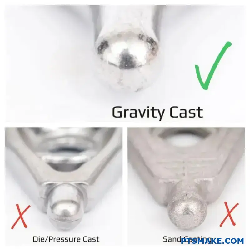
What are the main types of gravity casting processes?
Choosing the right gravity casting process is key. It directly impacts your project’s cost, quality, and lead time. Let’s break down the main types.
Sand Casting
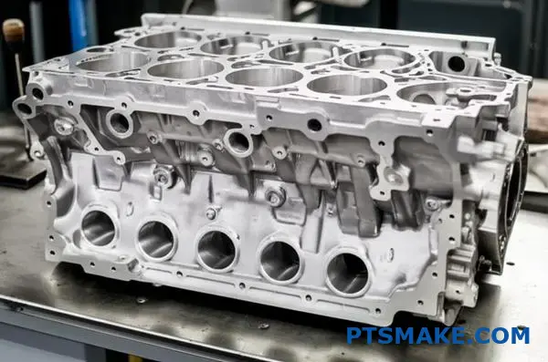
This method uses expendable sand molds. It’s great for very large parts or complex geometries. We often see it used for prototypes and low-volume runs.
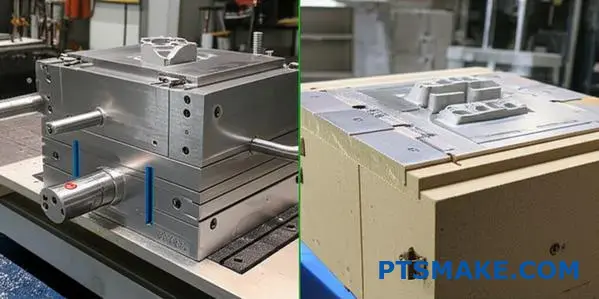
Permanent Mold Casting
Here, we use reusable metal molds, typically made of steel or iron. This process is ideal for higher volumes. It produces parts with a better surface finish.
Investment Casting
Also known as lost-wax casting. This technique creates highly detailed and intricate parts. It provides excellent surface finishes right out of the mold.
| Process | Mold Type | Typical Volume |
|---|---|---|
| Sand Casting | Expendable (Sand) | Low |
| Permanent Mold | Reusable (Metal) | High |
| Investment Casting | Expendable (Ceramic) | Low to Medium |

Applications and Trade-offs
Each gravity casting method has its place. Your choice depends entirely on your specific project needs. At PTSMAKE, we help clients weigh these factors to find the perfect fit.
Sand Casting Details
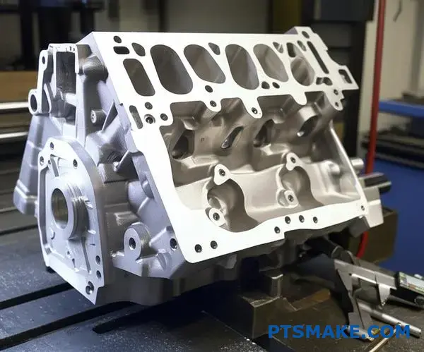
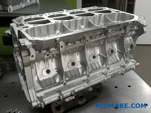
Sand casting is the go-to for engine blocks and large valve bodies. Its main advantage is low tooling cost and flexibility for design changes. However, it provides a rougher surface finish and less precise dimensional accuracy.
Permanent Mold Casting Details
This process is excellent for producing components like automotive pistons and gear housings. It delivers consistent quality and superior mechanical properties. The upfront mold cost is higher, but it pays off in high-volume production.
Investment Casting Details
This method shines when creating complex parts for aerospace or medical implants. It offers exceptional detail and precision. The process is more complex, and a well-designed gating system4 is critical to prevent defects.
Comparing Key Characteristics
| Feature | Sand Casting | Permanent Mold | Investment Casting |
|---|---|---|---|
| Surface Finish | Rough | Good | Excellent |
| Tolerance | Loose | Tight | Very Tight |
| Tooling Cost | Low | High | Medium |
| Part Complexity | High | Medium | Very High |
| Lead Time | Short | Long | Long |
In summary, the best gravity casting process depends on your project’s requirements. Key factors include production volume, part complexity, and desired finish. Understanding these trade-offs ensures you select the most effective and cost-efficient process for your components.
How are casting alloys classified for gravity processes?
To understand gravity casting, we first need to classify the alloys. The primary division is simple: ferrous versus non-ferrous. This initial split guides material selection.
Ferrous alloys are iron-based. This group includes cast irons and various steels.
Non-ferrous alloys lack significant iron content. Think of aluminum, copper, zinc, and magnesium. Each family has unique traits making it suitable for specific gravity casting applications.
Key Alloy Families
This basic classification helps narrow down choices based on core properties like strength, weight, and cost.
| Category | Primary Element | Common Examples |
|---|---|---|
| Ferrous | Iron (Fe) | Gray Iron, Ductile Iron, Carbon Steel |
| Non-Ferrous | Other | Aluminum Alloys, Brass, Bronze, Zinc Alloys |
This system forms the foundation for selecting the best material for a project.
Deeper Dive into Alloy Suitability
Choosing an alloy for gravity casting goes beyond this first step. The alloy’s behavior during the casting process is critical. We must consider its fluidity, shrinkage rate, and solidification range.
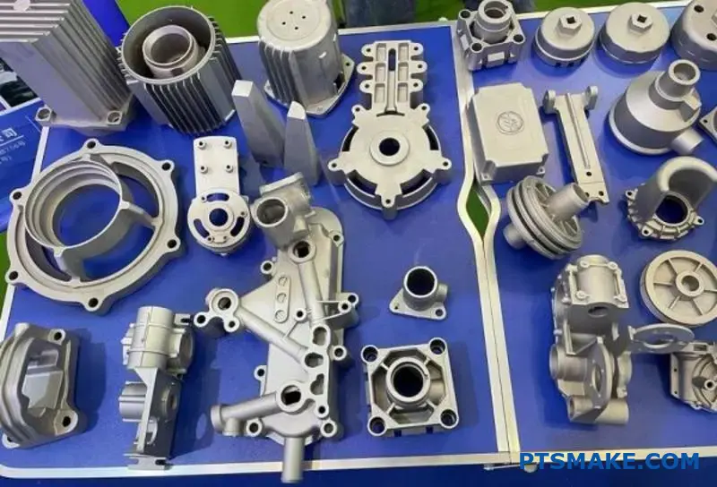
Non-Ferrous Alloys: The Popular Choice
Aluminum alloys are extremely common in gravity casting. Their excellent fluidity allows them to fill intricate mold cavities with ease. They are also lightweight and corrosion-resistant, perfect for automotive and aerospace parts.
Copper alloys, such as brass and bronze, are also excellent candidates. They provide superior strength, conductivity, and wear resistance. These are often used for plumbing fixtures, bearings, and decorative hardware. At PTSMAKE, we often recommend them for high-wear applications.
Ferrous Alloys: Strong but Demanding
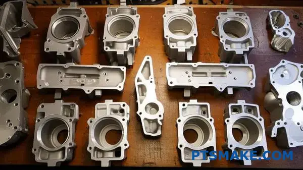
Cast irons are valued for their high strength, damping capacity, and low cost. They are staples for machine bases and engine blocks. However, their higher melting temperatures and density demand more robust equipment and processes.
Controlling the cooling rate is crucial to prevent defects. Poor control can affect the dendritic growth5 during solidification, which influences the part’s final integrity.
| Alloy Group | Key Advantages for Gravity Casting | Common Applications |
|---|---|---|
| Aluminum Alloys | High fluidity, lightweight, corrosion resistance | Engine components, transmission housings |
| Copper Alloys | High strength, good thermal conductivity | Bushings, valves, marine hardware |
| Cast Irons | Low cost, high compressive strength | Machine frames, brake drums |
Alloy selection is a balance between performance needs and manufacturing realities.
Classifying alloys as ferrous or non-ferrous provides a starting point. However, properties like fluidity and shrinkage determine suitability for gravity casting. This choice is fundamental to achieving high-quality parts that meet project specifications and budget constraints.
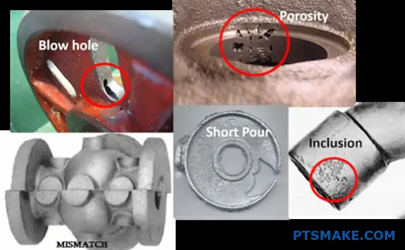
What is the system for classifying common casting defects?
To fix casting defects, you must first understand their origin. A random list of problems is not helpful. We need a system.
Grouping defects by their cause creates a powerful diagnostic tool. It turns confusion into a clear action plan. This is how we approach troubleshooting.
The Three Main Defect Families
We can sort most issues into three logical groups. This helps us focus our investigation and find the root cause efficiently, saving time and resources.
| Defect Category | Primary Cause | Common Examples |
|---|---|---|
| Filling Related | Issues with molten metal flow | Misruns, Cold Shuts |
| Solidification Related | Problems during cooling and shrinking | Shrinkage, Hot Tears |
| Gas Related | Trapped gases in the metal | Porosity, Blowholes |
This framework is the first step toward consistent, high-quality castings.
Understanding the "why" behind a defect is crucial. Simply identifying a flaw is not enough. We need to trace it back to a specific stage in the casting process.
Filling Related Defects
These issues occur when the mold cavity doesn’t fill properly. Think of it like pouring water too slowly into a complex ice tray. The metal might freeze before reaching every corner, causing a misrun or a cold shut.
Solidification Related Defects
This group of defects forms as the metal cools and solidifies. Shrinkage is a natural result of density change. If not managed with risers, it creates voids. Hot tears are fractures that happen when the casting is weak and under thermal stress. They often form in the interdendritic6 regions of the solidifying metal.
Gas Related Defects
Gas porosity is like bubbles trapped in a fizzy drink. These "bubbles" can come from the molten metal itself, moisture in the mold, or chemical reactions. In processes like Gravity Casting, controlling turbulence is key to prevent trapping atmospheric gases. At PTSMAKE, we carefully manage our melt and pouring processes to minimize this risk.
Here is a more detailed breakdown:
| Category | Specific Defect | Common Cause |
|---|---|---|
| Filling | Misrun | Pouring temperature too low |
| Filling | Cold Shut | Interrupted or slow metal flow |
| Solidification | Shrinkage | Inadequate feeding (riser design) |
| Solidification | Hot Tear | High thermal stress, mold restraint |
| Gas | Porosity | Dissolved gas in the melt, moisture |
By categorizing defects, we move from guessing to targeted problem-solving. It allows us to systematically analyze and improve the casting process, ensuring parts meet the required specifications for our clients.
Classifying defects by their origin—filling, solidification, or gas—is essential. This systematic approach provides a clear diagnostic framework, enabling engineers to identify and resolve root causes effectively, which improves part quality and reduces waste.
How do permanent mold and sand casting differ in application?
Choosing between permanent mold and sand casting is a key decision. It directly impacts your project’s budget, timeline, and final part quality. Each method has clear advantages for specific situations.
To help you decide, it’s best to compare them directly. Key factors include production volume, tooling cost, and the final part’s characteristics. Let’s look at a simple breakdown.
Key Practical Factors
A side-by-side comparison makes the best choice for your application much clearer.
| Factor | Permanent Mold Casting | Sand Casting |
|---|---|---|
| Production Volume | Medium to High (1,000+ parts) | Low to Medium (1 to 1,000 parts) |
| Tooling Cost | High initial investment | Low initial investment |
| Surface Finish | Smooth (100-400 µin Ra) | Rough (250-1000 µin Ra) |
| Dimensional Accuracy | High (±0.015 in.) | Low (±0.030 in.) |
| Achievable Complexity | Moderate; limited by mold release | High; complex internal cores possible |
The comparison table gives a great overview, but the "why" behind these numbers is where the real insights are. At PTSMAKE, we guide clients through these trade-offs daily. The decision isn’t just about cost; it’s about long-term value and product performance.
Production Volume and Cost Dynamics
The high upfront tooling cost for permanent molds can be intimidating. However, this cost is spread out over thousands of parts. This makes the per-piece price very competitive in mass production. For prototyping or small runs, sand casting’s low-cost tooling is unbeatable.
Quality and Precision Trade-offs
Permanent mold casting, often referred to as Gravity Casting, uses a metal mold. This allows for a faster solidification rate7, which creates a finer grain structure. Our tests show this often results in superior mechanical properties. The smooth mold also provides a much better surface finish, reducing the need for secondary machining.
Design Complexity Considerations
While permanent molds offer precision, they have limits. Undercuts and complex internal passages can be difficult. Sand casting shines here. Since the sand mold and cores are destroyed after use, you can achieve incredibly complex internal geometries that are impossible with a reusable metal mold.
In essence, your choice boils down to a balance. Sand casting provides low-cost flexibility for prototypes and complex, low-volume parts. Permanent mold casting delivers precision, superior finish, and cost-efficiency for high-volume production.
What are the different post-casting processes and their purposes?
A raw casting is rarely the final product. It’s the starting point. Post-casting processes are crucial. They transform a rough part into a functional component.
These secondary operations are essential. They ensure the part meets all design specifications. This includes strength, dimensions, and appearance.
Let’s explore the most common steps.
| Operation | Primary Purpose |
|---|---|
| De-gating/Riser Removal | Remove excess material |
| Heat Treatment | Enhance mechanical properties |
| Machining | Achieve final, precise dimensions |
| Surface Finishing | Improve surface quality and look |
After a part comes out of the mold, the real work begins. These secondary operations are not optional. They are vital for creating a reliable final product. Each step serves a distinct and important purpose.
Initial Cleanup: De-gating and Riser Removal
The first step is always cleanup. We remove the gating system and risers. These are channels that allow molten metal to flow into the mold. They are necessary for casting but not part of the final design. This is often done with saws or grinders.
Building Strength: Heat Treatment
Many alloys, especially aluminum, require heat treatment. The T6 temper is a common example. It involves a process of Solutionizing8 and aging. This significantly increases the material’s strength and hardness. Without it, the part would not perform as intended under stress.
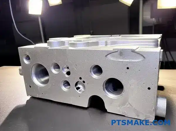
Achieving Precision: Machining
Casting alone cannot achieve very tight tolerances. For parts made with methods like Gravity Casting, machining is key. At PTSMAKE, we use CNC machining. This allows us to create precise features. Think of threaded holes, flat surfaces, and exact diameters. It ensures the part fits perfectly in its assembly.
The Final Touch: Surface Finishing
Surface finishing improves both function and aesthetics. It can prepare a surface for painting or coating. It also removes any imperfections.
| Finishing Method | Outcome |
|---|---|
| Shot Blasting | Creates a clean, uniform matte finish |
| Anodizing | Adds a corrosion-resistant layer (for aluminum) |
| Powder Coating | Applies a durable, decorative finish |
| Polishing | Creates a smooth, reflective surface |
These post-casting processes are critical. They bridge the gap between a rough casting and a high-performance, finished component. Each step adds value, ensuring the final part is strong, precise, and ready for use.
A Practical DFM Checklist for Gravity Casting
Is your part truly ready for gravity casting? A simple checklist can save you headaches later. Design for Manufacturability (DFM) is key.
It helps identify potential issues early. We can avoid costly mold changes and production delays.
Key Geometric Factors
Wall Thickness
Ensure wall thickness is as uniform as possible. This prevents defects caused by uneven cooling rates.
Draft Angles
Proper draft angles are essential for part ejection. Without them, parts can get stuck in the mold.
| Feature Type | Recommended Draft Angle |
|---|---|
| External Walls | 1-3 Degrees |
| Internal Walls | 2-5 Degrees |
| Deep Pockets | 3+ Degrees |
Let’s dive deeper into a more comprehensive checklist. At PTSMAKE, we use a similar process to review every design before we even think about cutting a mold. This proactive approach ensures a smoother production run for our clients.
Advanced DFM Considerations
Section Transitions
Avoid abrupt changes in thickness. Use generous radii and fillets to blend sections smoothly. This minimizes stress concentration points and potential cracking. Sharp corners are a major source of failure in casting.
Ribs and Bosses
Design ribs to be thinner than the walls they support. This prevents sink marks on the part surface. Following this rule maintains a part’s aesthetic and structural quality.
| Design Element | Bad Practice | Good Practice |
|---|---|---|
| Section Change | Sharp 90° corner | Blended with a large radius |
| Rib Height | > 3x Wall Thickness | < 1.5x Wall Thickness |
| Bosses | Solid, thick sections | Cored out to maintain wall |
Internal Features and Undercuts
Minimize complex internal features. They often require intricate and expensive cores. Undercuts should be avoided entirely if possible, as they add significant complexity and cost to the mold design. During the design phase, we often work with clients to eliminate undercuts without compromising function. This is critical for controlling costs. Proper design also accounts for volumetric shrinkage9, ensuring the final part meets dimensional specs.
A Design for Manufacturability (DFM) checklist is a vital tool. It helps you assess wall thickness, draft angles, and complexity. This ensures your part is optimized for the gravity casting process, preventing costly errors and improving part quality.
How do you systematically diagnose the cause of shrinkage porosity?
A diagnostic flowchart is my go-to tool. It replaces guesswork with a logical process. This method helps us save time and material.
First, you must identify the porosity’s exact location. This simple step provides the most critical clue.
Key Starting Questions
Is the defect in a heavy section of the casting? Or is it located far from the riser or gate? The answer guides your next steps. This is vital in processes like Gravity Casting.
Initial Diagnostic Path
| Porosity Location | Initial Hypothesis |
|---|---|
| Heavy/Thick Section | Inadequate Feeding |
| Far From Riser | Premature Solidification |
| Near the Ingate | Gating System Issue |
This structured approach quickly narrows down the potential root causes.
Analyzing the Feeding Path
A flowchart simplifies complex problems. Let’s say you find porosity in a thick section. This part cools last. It needs a constant supply of molten metal to compensate for shrinkage.
If this supply is cut off, a void forms. This points directly to an inadequate feeding problem. The riser might be too small or it froze too early.
Inadequate Riser Design
Now, consider porosity far from the riser. This suggests the metal traveled a long distance. It likely began to solidify before reaching the final destination. The feeding path is insufficient.
In our work at PTSMAKE, we analyze the part’s geometry. A section with a higher Solidification modulus10 will cool slower. It must be fed by a riser with an even higher modulus. This ensures the riser is the last part to freeze.
Diagnostic Decision Matrix
| Observation | Likely Cause | Primary Investigation Area |
|---|---|---|
| Porosity in isolated thick section | Poor local feeding | Riser size and placement |
| Porosity along a thin wall | Flow path restriction | Gate and runner design |
| Porosity near the riser | Riser not functioning | Riser neck design or material |
By following this logic, we methodically eliminate variables. This leads to a precise and effective solution, avoiding costly trial-and-error adjustments.
A diagnostic flowchart starts with the defect’s location. This visual clue systematically guides you to the root cause, efficiently distinguishing between poor feeding paths and flawed riser design, which streamlines the entire troubleshooting process for your team.
What quality control checks are essential during production?
In-process checks are the backbone of quality control. They happen right on the production floor. They allow us to catch issues early, before they become major problems. It’s about proactive prevention.
Verifying Critical Parameters
Controlling variables is key in manufacturing. For a process like Gravity Casting, temperature is everything. We must verify the melt temperature constantly. This ensures proper metal flow and solidification.
The table below shows some key checks.
| Check Point | Purpose | Frequency |
|---|---|---|
| Melt Temperature | Ensures fluidity & prevents defects | Continuous/Per Batch |
| Mold Temperature | Affects cooling rate & part finish | Per Setup |
| Cycle Time | Maintains process consistency | Continuous |
First-Off and Dimensional Checks
We visually inspect the first part from any run. This "first-off" casting tells us a lot. We look for surface flaws or incomplete fills. Then, we check critical dimensions with precision tools. This confirms the setup is correct.
The Power of Continuous Monitoring
A single check is just a snapshot. Real quality control comes from consistent monitoring. It’s not enough to check the first part. We must monitor process parameters throughout the entire production run. This consistency is what separates good parts from great ones.
At PTSMAKE, we track these parameters in real-time. This approach helps us maintain stability. It ensures the 1000th part is identical to the first. This constant vigilance prevents drift and variation. Any deviation triggers an immediate alert for correction.
Why In-Process Checks Matter More Than Final Inspection
Relying only on final inspection is a costly mistake. It means you’ve already spent time and resources making bad parts. In-process checks are about building quality into the product from the start.
This proactive approach helps us understand our manufacturing stability. In our experience, this is crucial for assessing process capability11 over the long term. A stable process produces predictable, high-quality results every time. It reduces scrap and rework, saving time and money.
| Aspect | Proactive (In-Process) | Reactive (Final) |
|---|---|---|
| Focus | Prevention of defects | Detection of defects |
| Cost Impact | Low (minor adjustments) | High (scrap, rework) |
| Efficiency | High | Low |
| Customer Impact | Consistent Quality | Risk of delays |
In-process checks are non-negotiable. Verifying temperature, inspecting the first casting, and monitoring parameters ensure every component meets specifications. This proactive approach prevents defects and builds quality directly into the manufacturing process, guaranteeing reliable and consistent outcomes.
How would you adapt a process for a new, unfamiliar alloy?
Facing a new alloy requires a clear strategy. You can’t just use the old process and hope for the best.
It all starts with research. We dig into the alloy’s material datasheet. What is its melting point? How much does it shrink?
After research, we plan small trials. The key is to adjust one parameter at a time. This helps us find the perfect process window without creating confusion. It’s a methodical approach.
| Initial Research Focus | Key Data Points |
|---|---|
| Thermal Properties | Melting Point, Pouring Temperature |
| Physical Properties | Density, Shrinkage Rate |
| Mechanical Properties | Expected Hardness, Tensile Strength |

A material datasheet provides a great starting point. But it’s just theory. Real-world manufacturing introduces variables the datasheet can’t predict. At PTSMAKE, we bridge this gap with systematic trials.
The Trial Phase: One Step at a Time
We begin with small, controlled test runs. The core principle is changing only one variable for each test. If you adjust temperature and pressure at the same time, you won’t know which change made the difference. This methodical approach is crucial.
For a process like Gravity Casting, the material’s solidification range12 deeply influences the outcome. A wider range might require slower cooling to prevent defects.
Establishing the New Process Window
Our goal is to define a stable process window. This means identifying the upper and lower limits for key parameters. It ensures consistent quality for every part.
| Parameter to Test | Adjustment Range | Goal |
|---|---|---|
| Pouring Temperature | +/- 5% of recommended | Optimize fluidity & reduce defects |
| Mold Temperature | +/- 10°C from baseline | Control cooling rate |
| Cooling Method | Air cool vs. controlled cooling | Refine grain structure |
This testing provides a reliable roadmap. It turns an unfamiliar alloy into a predictable part of our production process.
A successful adaptation hinges on two steps. First, conduct thorough research on the alloy’s properties. Second, use systematic, single-variable trials to establish a reliable new process window. This minimizes risk and ensures quality.
Given a complex part, how do you decide its orientation?
Guesswork has no place in precision manufacturing. For complex parts, choosing the right orientation is a calculated decision. We use a decision matrix.
This tool helps us systematically evaluate options. It removes bias and focuses on technical facts.
Key Evaluation Criteria
We score each potential orientation against key factors.
| Criterion | Importance | Goal |
|---|---|---|
| Critical Surfaces | High | Flawless finish, placed in drag |
| Heavy Sections | High | Easy risering, prevent shrinkage |
| Venting | Medium | Allow gas to escape easily |
This structured approach ensures we make the best choice, every time. It balances competing needs for a successful outcome.
A decision matrix turns a complex puzzle into a clear path. It forces us to quantify what often feels like intuition. Let’s break down the criteria for this evaluation.
Placing Critical Surfaces in the Drag
The drag is the lower half of the mold. Any impurities in the molten metal tend to float to the top, or the cope.
By placing cosmetically important or tight-tolerance surfaces in the drag, we ensure they are formed with the cleanest material. This minimizes surface defects and reduces rework.
Positioning Heavy Sections for Risering
Heavy sections cool slower than thin walls. Without a source of molten metal, this can lead to defects as the material contracts. This is where volumetric shrinkage13 is a critical factor to manage.
We orient the part so these sections are high up. This makes it easier to add risers above them. Risers act as reservoirs, feeding the part as it solidifies. This process is crucial in methods like Gravity Casting.
Ensuring Proper Venting
Trapped air or gas is a recipe for disaster. It causes porosity, creating weak spots in the final part.
High points in the mold cavity are natural traps for gas. The orientation must provide a clear path for vents to be placed at these highest points, allowing air to escape as the metal fills the mold.
| Orientation Option | Critical Surface (Score 1-5) | Risering Access (Score 1-5) | Venting Ease (Score 1-5) | Total Score |
|---|---|---|---|---|
| Option A | 5 | 3 | 3 | 11 |
| Option B | 3 | 5 | 4 | 12 |
| Option C | 4 | 4 | 5 | 13 |
Based on the matrix, Option C provides the most balanced result for this hypothetical part.
A decision matrix transforms a complex choice into a logical, data-driven process. It balances surface quality, structural integrity, and defect prevention to find the optimal part orientation, ensuring consistent and high-quality results.
How do you troubleshoot a casting with multiple, interacting defects?
When a casting has several defects, it’s easy to get lost. You might fix one problem, only to find another one gets worse. The key is to stop chasing symptoms. You need a structured problem-solving method.
This means finding the primary defect first. This is the issue causing the most rejections. By focusing your efforts here, you often solve other, secondary defects automatically. This saves time and resources.
| Troubleshooting Approach | Outcome |
|---|---|
| Random Fixes | Unpredictable results, wasted effort |
| Structured Method | Efficient, reliable, solves root causes |
The Power of a Systematic Approach
A systematic approach turns chaos into a clear process. Start by collecting data. Which defect is most common? Is it porosity, shrinkage, or something else? The numbers will point you to the primary defect. Don’t just guess.
Once you identify it, the real work begins: root cause analysis. Instead of just patching the surface issue, you must dig deeper to find the fundamental cause. It’s about understanding the causal chain14 where one problem directly leads to others.
For example, in a Gravity Casting process, improper pouring temperature might be the root cause. This could lead to a primary defect like porosity. This porosity, in turn, can cause a secondary defect, such as a poor surface finish or reduced mechanical strength. Fixing the temperature solves all three.
At PTSMAKE, we use this method to dissect complex issues. It ensures we don’t just solve the problem for now, but prevent it from recurring.
Primary vs. Secondary Defect Example
| Root Cause | Primary Defect | Secondary Defect |
|---|---|---|
| Low Mold Temperature | Cold Shuts | Incomplete Fill |
| Entrapped Gas | Gas Porosity | Blisters, Poor Finish |
| Inadequate Gating | Shrinkage | Cracks, Warping |
To troubleshoot interacting defects, adopt a structured method. First, identify the primary defect causing the most rejects. Then, find and fix its root cause. This disciplined approach often resolves secondary issues simultaneously, leading to a more efficient and permanent solution.
How would you justify switching from sand to permanent mold casting?
Making the switch from sand to permanent mold casting requires a solid business case. It’s not just about comparing initial quotes. You must analyze the total cost per part.
This data-driven approach reveals the true long-term value. Let’s break down the key financial factors you should consider before making a decision.
Key Cost Considerations
| Factor | Sand Casting | Permanent Mold Casting |
|---|---|---|
| Tooling Cost | Low | High |
| Labor per Part | High | Low |
| Scrap Rate | Higher | Lower |
| Machining | Often Required | Minimal to None |
Analyzing the Key Trade-Offs
A comprehensive analysis must weigh the high initial mold investment against long-term operational savings. The justification hinges on understanding these trade-offs and how they impact your bottom line over the entire product lifecycle. This is where many teams miscalculate.
Production Rate and Labor
Permanent molds enable faster cycle times. In our experience with clients, this can dramatically reduce the labor cost allocated to each part. Higher automation potential further drives this cost down, making it very efficient for high-volume production runs.
Material Waste and Quality
Permanent mold casting, often a type of Gravity Casting, produces parts with superior surface finish and dimensional accuracy. This significantly reduces material waste from scrap.
It also minimizes the need for costly secondary machining operations, which is a major hidden cost in sand casting. The key is to properly calculate the amortization15 of the mold over the entire production run.
Cost Impact Breakdown
| Metric | Sand Casting Impact | Permanent Mold Impact |
|---|---|---|
| Tooling Investment | Low initial barrier | High upfront cost |
| Production Speed | Slower cycles | Faster cycles, higher output |
| Post-Processing | More machining needed | Less machining, better finish |
| Total Cost | Cheaper for low volume | Cheaper for high volume |
A data-driven business case is vital. It involves analyzing the total cost per part by factoring in tooling, production rates, labor, and quality improvements. This comprehensive view ensures your decision to switch is financially sound and strategically beneficial for the long term.
How do you implement a process control plan for a high-volume part?
Statistical Process Control (SPC) is essential for high-volume parts. It provides the framework for monitoring and maintaining consistency.
The first step is identifying critical process parameters. These are the variables that directly impact quality.
Next, you establish control limits to define acceptable variation. A clear reaction plan is then created for any deviations. This ensures proactive quality management.
A simple breakdown of key SPC elements is below.
| Element | Purpose |
|---|---|
| Critical Parameters | Focus on what truly impacts part quality. |
| Control Limits | Define the natural variation of the process. |
| Reaction Plan | Provide clear instructions for deviations. |

Designing an effective SPC plan requires a systematic approach. It is not just about collecting data; it is about using that data to make intelligent decisions and prevent defects before they occur. This proactive stance is the cornerstone of modern quality control.
Identifying Critical Process Parameters
The foundation of any SPC plan is knowing what to measure. You cannot monitor everything. Focus on the few parameters that have the biggest impact on the final part.
In a process like Gravity Casting, the temperature of the molten aluminum is a critical parameter. If it’s too high or too low, it can affect the material’s flow and structural integrity.
At PTSMAKE, we collaborate with our clients during the design phase. We identify these critical features and process inputs together. This ensures our control plan is focused and effective.
Establishing Control Limits with Charts
Control charts are the primary tools of SPC. They help visualize process performance over time. For variables like temperature or pressure, X-bar and R charts are commonly used.
The X-bar chart tracks the average of subgroups, showing process centering. The R chart tracks the range within subgroups, indicating process variability.
These limits are calculated from your own process data. They represent the voice of the process. This helps distinguish normal variation from Assignable Cause Variation16 that signals a problem.
Creating a Clear Reaction Plan
A control chart is useless without a reaction plan. This plan details the exact steps to take when a process goes out of control. It eliminates guesswork during production.
| Condition | Immediate Action | Follow-up Action |
|---|---|---|
| Point outside control limit | Stop production. Quarantine suspect parts. | Investigate the source (e.g., machine, operator). |
| A clear trend or pattern | Alert the process engineer. Do not adjust. | Analyze data to identify the cause of the shift. |
A well-defined reaction plan minimizes the production of non-conforming parts. It turns data into corrective action swiftly.
A strong SPC plan is built on three pillars: identifying critical parameters, setting statistical control limits, and defining clear reaction plans. This framework moves quality control from reactive inspection to proactive process management, which is essential for high-volume manufacturing success.
Discover Superior Gravity Casting Solutions with PTSMAKE
Ready for flawless gravity casting parts and expert support? Trust PTSMAKE to deliver precision, speed, and quality for your next project. Contact us now for a tailored quote—let’s build success together with a manufacturing partner you can rely on!

Discover how this pressure is critical for defect-free and detailed castings. ↩
Understand how this crystal growth impacts the final mechanical properties of the casting. ↩
Learn how this force impacts casting integrity and discover strategies to manage it effectively in your designs. ↩
Discover how the gating system’s design ensures optimal metal flow and casting integrity. ↩
Discover how metal crystal formation during cooling affects a part’s mechanical properties and overall strength. ↩
Explore the microstructural mechanics that directly impact casting strength and failure points. ↩
Discover how solidification impacts the material’s strength and overall part integrity. ↩
Learn how this critical heating and cooling cycle unlocks the full potential of your casted material. ↩
Understand how material shrinkage impacts the final dimensions and integrity of your cast parts. ↩
Learn how this critical parameter directly influences casting design and defect prevention. ↩
Learn how this metric predicts if your process can consistently meet quality specifications. ↩
Understand how this property affects casting defects and final part quality. ↩
Understand how this cooling effect creates voids and how proper design counteracts it for solid parts. ↩
Learn how one defect can trigger another to improve your diagnostic skills. ↩
Understand how to spread tooling costs over production volume to calculate the true cost per part. ↩
Understand how to find specific, fixable problems that cause process instability and defects. ↩