You’re looking for a reliable aluminum die casting manufacturer, but the market is flooded with suppliers who promise precision yet deliver inconsistent quality, delayed timelines, and poor communication that leaves your projects in limbo.
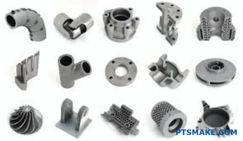
PTSMAKE specializes in custom aluminum die casting with advanced high-pressure and low-pressure processes, delivering precision parts from prototype to full production for aerospace, automotive, and electronics industries.
Choosing the right casting partner involves more than comparing quotes. The success of your project depends on understanding casting processes, alloy selection, quality standards, and production workflows. This guide covers the essential knowledge you need to make informed decisions and avoid costly manufacturing mistakes.
What are the major categories of aluminum casting processes?
Choosing the right aluminum casting process is vital. Your decision impacts cost, production speed, and part quality. Think of it as a map with two main routes.
One route uses molds that are destroyed after one use. The other route uses durable, reusable molds for high-volume production. Each has unique benefits.
Main Casting Families
Understanding these core families is the first step. It helps narrow down your options significantly.
| Process Family | Mold Type | Common Use Case |
|---|---|---|
| Sand Casting | Expendable (Sand) | Large parts, prototypes |
| Die Casting | Permanent (Steel) | High-volume, complex parts |
| Investment Casting | Expendable (Ceramic) | Intricate, high-precision parts |
This map simplifies a complex manufacturing landscape.
The fundamental difference lies in the mold material and its lifespan. This single factor creates two distinct categories of aluminum casting.
Expendable Mold Casting
In these processes, the mold is created for a single casting. It is broken away to retrieve the finished part. Sand casting and investment casting fall into this group.
Sand casting uses a mold made of compressed sand. It’s great for large components and prototypes. The mold’s permeability1 allows gases to escape, which is critical.
Investment casting, or lost-wax casting, uses a ceramic mold. It offers excellent surface finish and is ideal for highly complex shapes.
Permanent Mold Casting
Here, the molds are typically machined from steel. They are used for thousands of cycles, making them cost-effective for mass production.
Die casting is the most common example. It forces molten aluminum into the mold cavity under pressure. This results in parts with excellent dimensional accuracy.
The table below breaks down the core mechanism for each.
| Casting Process | Core Mechanism | Key Advantage |
|---|---|---|
| Sand Casting | Gravity-fed into a sand mold | Low tooling cost, large parts |
| Investment Casting | Molten metal poured into a ceramic shell | High complexity, fine details |
| Die Casting | High-pressure injection into a steel die | Fast cycles, high precision |
| Permanent Mold | Gravity-fed into a steel mold | Better finish than sand casting |
Aluminum casting is split into expendable and permanent mold methods. The first is for lower volumes and complex designs. The second is for high-volume production where tooling costs can be spread out over many parts, which is a core service at PTSMAKE.
How are aluminum alloys designated and practically grouped for casting?
Understanding aluminum alloy designations is crucial. It’s not just a random set of numbers. It’s a code that tells you the alloy’s family and composition. This system, established by The Aluminum Association, helps us select the right material.
The format is typically AXXX.X. The first digit reveals the primary alloying element. This is the most important clue to its properties. For anyone involved in aluminum casting, mastering this system is fundamental.
The Main Alloy Groups
Here is a quick breakdown of the main series for casting alloys:
| Series | Principal Alloying Element(s) |
|---|---|
| 1xx.x | 99.00% Minimum Aluminum |
| 2xx.x | Copper (Cu) |
| 3xx.x | Silicon (Si) + Copper (Cu) and/or Magnesium (Mg) |
| 4xx.x | Silicon (Si) |
| 5xx.x | Magnesium (Mg) |
| 7xx.x | Zinc (Zn) |
| 8xx.x | Tin (Sn) |
This simple chart is the starting point for material selection.
Decoding the Designation System
Let’s break down the AXXX.X system further. The first digit, as we’ve seen, identifies the main alloy group. The second and third digits identify the specific alloy within that group. They are essentially arbitrary numbers assigned to unique compositions.
The digit after the decimal point is also important. A ".0" indicates a final casting, while a ".1" or ".2" signifies an ingot with specific composition limits. This distinction is vital for foundries. The "A" prefix before the numbers signifies a minor modification to the original alloy composition.
Practical Groupings for Casting
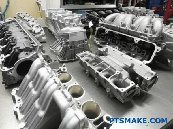
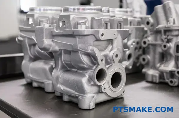
In our projects at PTSMAKE, we group alloys by application needs. For instance, the 3xx.x series is the workhorse of die casting. A380 is a go-to choice for its excellent balance of castability, mechanical properties, and cost. It’s found in everything from engine blocks to electronic housings.
A356, another 3xx.x series alloy, is popular for sand and permanent mold casting. It offers great corrosion resistance and weldability, making it ideal for aerospace and automotive parts. The 5xx.x series, primarily alloyed with magnesium, provides superior corrosion resistance, especially in marine environments. The silicon in the 3xx.x series helps create a eutectic2 microstructure, which improves casting fluidity.
| Alloy | Series | Common Casting Method | Key Characteristics |
|---|---|---|---|
| A380 | 3xx.x | Die Casting | Excellent fluidity, pressure tightness, good strength |
| A356 | 3xx.x | Sand, Permanent Mold | High strength, good corrosion resistance, weldable |
| 518 | 5xx.x | Die Casting | Excellent corrosion resistance, good finishing |
| 6061 | 6xx.x | Wrought (Sometimes Cast) | Good strength, weldability, machinability |
While 6061 is mainly a wrought alloy, its properties make it a familiar benchmark for engineers.
The designation system is a roadmap. It guides engineers and manufacturers to the alloy’s main ingredients and likely performance. This code simplifies material selection, ensuring the final part meets all project specifications, from strength to corrosion resistance.
How does aluminum alloy composition dictate its practical casting behavior?
Alloying elements are the levers we pull. They fine-tune an aluminum alloy’s behavior. Silicon, copper, and magnesium are the most common. Each one changes the game.
They directly influence how the metal flows and cools. This dictates the final part’s properties.
The Role of Silicon (Si)
Silicon is the number one friend of castability. It dramatically improves fluidity. This helps the molten metal fill intricate mold details. It also reduces solidification shrinkage.
The Impact of Copper (Cu) and Magnesium (Mg)
Copper and magnesium are added for strength. They allow the alloy to be heat-treated. This process significantly boosts hardness and mechanical performance. The trade-off can be reduced ductility.
| Alloying Element | Primary Impact on Casting | Key Benefit |
|---|---|---|
| Silicon (Si) | Increases Fluidity | Castability |
| Copper (Cu) | Improves Strength | Performance |
| Magnesium (Mg) | Enables Heat Treatment | Hardness |
Choosing the right alloy is a balancing act. It’s not just about the final properties. It’s about how those properties are achieved through the manufacturing process. This is a conversation we have with clients at PTSMAKE daily.
Understanding Element Interactions
The magic happens when elements are combined. Silicon improves fluidity, but adding copper can increase the risk of hot tearing. This is cracking that occurs as the casting cools and shrinks. The alloy becomes brittle in a specific temperature window.
Magnesium works with silicon to form magnesium silicide. This compound is crucial for age hardening during heat treatment. But getting the ratio wrong can cause problems. In our experience, too much magnesium makes the alloy sluggish and prone to defects.
A wider solidification range3 often means more risk. The part stays in a mushy state for longer. This increases susceptibility to porosity and tearing.
Selecting Process Parameters
The alloy’s composition dictates our process. An alloy with high copper content needs carefully controlled cooling rates. This minimizes thermal stress. An alloy designed for high fluidity allows for thinner walls in the final part design. This is key for successful aluminum casting projects.
Our process engineers adjust parameters based on these chemical fingerprints. It ensures we meet specifications every time.
| Alloy Trait | Process Consideration |
|---|---|
| High Fluidity (Si) | Enables complex, thin-walled designs |
| High Strength (Cu) | Requires controlled cooling rates |
| Heat Treatable (Mg) | Needs specific thermal processing |
| Wide Solidification | Demands careful gating & riser design |
Alloying elements like Silicon, Copper, and Magnesium fundamentally define an aluminum alloy’s casting behavior. They control everything from fluidity and solidification to heat treatment response. Mastering these relationships is essential for selecting optimal process parameters and achieving high-quality parts.
How do you select the right casting process for your parts?
Choosing a casting process can feel complex. At PTSMAKE, we simplify this by using a decision matrix. This tool helps us focus on what truly matters for your project.
It’s a structured way to compare options. We evaluate based on five key factors. This ensures the final choice aligns perfectly with your goals.
Key Practical Factors
A decision matrix brings clarity. It balances technical needs with business objectives, guiding you to the best-fit manufacturing method.
| Factor | Key Consideration |
|---|---|
| Production Volume | How many parts will you need over the product’s lifetime? |
| Part Complexity | How intricate are the design’s features and geometry? |
| Required Tolerances | What level of dimensional accuracy is necessary? |
| Surface Finish | What is the aesthetic or functional requirement for the surface? |
| Target Cost | What is the budget for tooling and the final per-part price? |
Applying the Framework: A Real-World Example
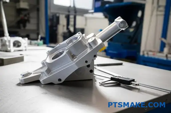
Let’s apply this matrix to a common scenario. We need to choose between die casting and sand casting for a new aluminum housing.
This part requires high precision and a smooth finish. It will be produced in large quantities, exceeding 50,000 units annually.
For high-volume production, the efficiency of die casting is a major advantage. Its high initial tooling cost is spread over many parts. This makes the per-part cost very low.
The higher initial investment for die casting is offset by a lower per-part cost, a concept known as tooling amortization4.
Sand casting, with its lower tooling cost, is better suited for prototypes or low-volume runs.
Comparing Processes for the Aluminum Housing
The table below shows a direct comparison based on our key factors. For this specific high-volume, high-precision part, die casting is the clear winner.
| Factor | Die Casting | Sand Casting |
|---|---|---|
| Production Volume | Excellent (50,000+ units) | Poor (Better for < 1,000 units) |
| Part Complexity | Excellent (thin walls, fine detail) | Fair (Thicker sections required) |
| Tolerances | Excellent (Tight, consistent) | Poor (Loose, less repeatable) |
| Surface Finish | Excellent (Smooth, ready for paint) | Poor (Requires secondary finishing) |
| Target Cost | Excellent (Low per-part cost) | Poor (High per-part cost at volume) |
Using a decision matrix removes the guesswork. It provides a data-driven basis for your choice, balancing cost, quality, and volume. This ensures you select the most effective and economical casting process for your specific part’s requirements.
What defines a ‘good’ casting beyond visual inspection?
Beyond a flawless surface, a good casting is defined by data. We focus on Critical-to-Quality (CTQ) metrics. These are the measurable characteristics that guarantee performance.
They translate your design needs into our production targets. This ensures the final part functions perfectly under real-world stress.
Key Performance Metrics
We look at strength, accuracy, and integrity. These numbers tell the true story of a casting’s quality. They are not subjective.
| Metric | Why It’s Critical |
|---|---|
| Mechanical Properties | Resists operational forces |
| Dimensional Accuracy | Ensures a perfect fit and function |
| Pressure Tightness | Prevents leaks in sealed systems |
The Deeper Dive into CTQs
Every application places unique demands on a part. A pretty casting that fails under pressure is useless. That’s why we map CTQs directly to your requirements.
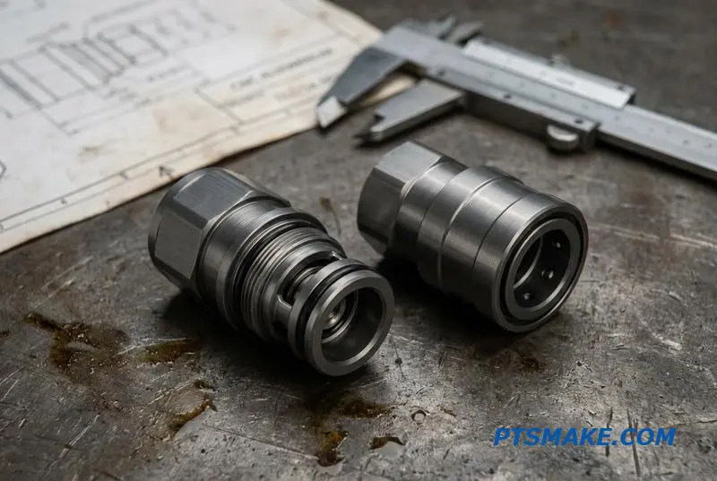
For parts containing fluids or gases, pressure tightness is paramount. Even microscopic porosity can lead to failure. We see this often in hydraulic components.
Surface Finish and Functionality
Surface finish, measured as Ra, is another critical metric. It’s not just for aesthetics. A specific finish is often required for sealing surfaces. It can also reduce friction in moving parts.
Matching Metrics to Stress
An aluminum casting for an automotive turbocharger has different needs than one for a medical device enclosure. One requires thermal stability and pressure tightness. The other needs a high-quality surface finish for sterilization. The material’s tensile strength5 is often a core CTQ. At PTSMAKE, we help you define and achieve these targets.
| Application Example | Most Critical CTQ | Reason for Importance |
|---|---|---|
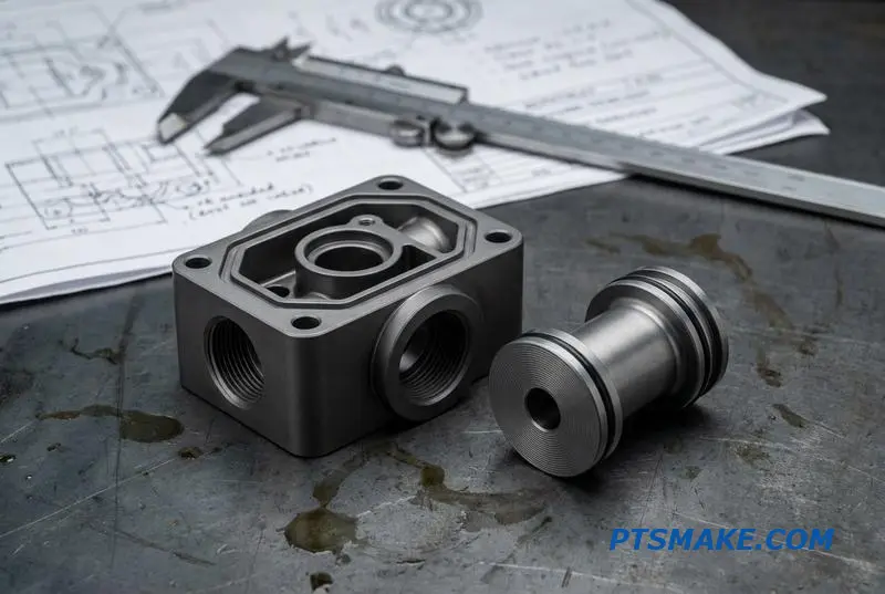
| Hydraulic Valve Body | Pressure Tightness | Must contain high-pressure fluid without any leakage. |
| Aerospace Structural Part | Mechanical Strength | Must bear significant loads without deformation or failure. |
| Electronic Enclosure | Dimensional Tolerance | Must align perfectly with PCBs and other components. |
Critical-to-Quality metrics transform your design intent into tangible, verifiable specifications. They are the true language of quality, ensuring the part performs exactly as needed in its final application, from fit to function under stress.
How are common Aluminum casting defects systematically classified and identified?
Let’s group common aluminum casting defects. This helps us find the root cause quickly. We sort them by their appearance and underlying cause.
Grouping by Appearance and Cause
This method simplifies diagnosis. We can put defects into families. These include porosity, cracks, and surface imperfections. Each has a distinct visual signature.
Here is a quick guide:
| Defect Type | Visual Cue |
|---|---|
| Shrinkage Porosity | Jagged, angular voids |
| Gas Porosity | Smooth, spherical bubbles |
| Hot Tears | Ragged, branching cracks |
Recognizing these signs on a casting is the first step. It guides our entire problem-solving approach.
A visual check is just the start. Understanding the root cause is key to a permanent fix. Each defect tells a story about the aluminum casting process.
Digging Deeper: From Visual Cues to Root Causes
Porosity: Shrinkage vs. Gas
Shrinkage porosity forms from poor feeding during solidification. This creates jagged voids. In contrast, gas porosity is trapped hydrogen. It results in smooth, round bubbles. This distinction is critical for process control.
Sometimes, defects are internal. Visual inspection is not enough. We may need to section a part for metallographic analysis6. This process reveals the internal structure of the flaw. It tells us the full story of its formation.
Cracks and Surface Flaws
Hot tears are cracks forming at high temperatures from thermal stress. Cold shuts and misruns are different. They happen when molten metal flows poorly. Or when it solidifies too early. They appear as lines or incomplete sections on the surface.
| Feature | Hot Tears | Cold Shuts |
|---|---|---|
| Cause | Thermal stress during cooling | Premature solidification |
| Appearance | Irregular, branching cracks | A distinct line or seam |
| Location | Areas with high stress | Where two metal flows meet |
At PTSMAKE, we don’t just identify defects. We analyze their root cause to prevent them from recurring. This ensures every component meets the highest quality standards.
Classifying defects by visual appearance and root cause is essential. This systematic approach allows for targeted solutions. It ensures consistent quality in every aluminum casting, from identifying porosity to analyzing hot tears.
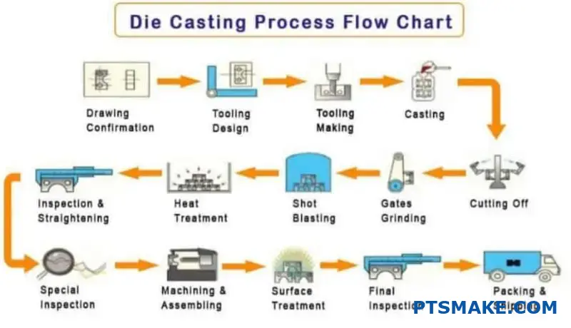
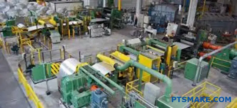
What is the typical workflow of a Aluminum casting production line?
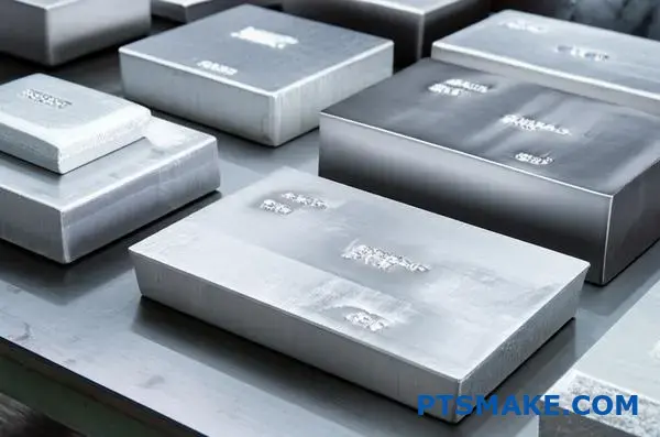
The aluminum casting production line is a systematic journey. It transforms a raw aluminum ingot into a precise, finished component. Every step is critical.
From start to finish, the process demands control. Each phase builds upon the last. A small error early on can cause major defects later.
Key Production Stages
Here is a simplified breakdown of the workflow. We will explore each of these stages in more detail.
| Stage | Key Activity | Purpose |
|---|---|---|
| 1. Preparation | Ingot Receiving & Melting | Convert solid raw material to liquid form. |
| 2. Casting | Pouring & Solidification | Shape the molten metal into the desired part. |
| 3. Finishing | Cleaning & Inspection | Prepare the part for its final application. |
This structured flow ensures consistency and quality.
A Step-by-Step Breakdown
Let’s look closer at each phase of the aluminum casting workflow. Understanding these details is key to managing production and ensuring part quality.
1. Material and Melting
It all starts with ingot receiving. We verify the material certification to ensure it meets project specifications. The ingots are then melted in a furnace and held at a precise temperature.
2. Metal Treatment
This step is non-negotiable for high-quality parts. Molten aluminum must be treated to remove impurities and dissolved gases. A process like degassing7 is essential to prevent porosity, which can compromise the structural integrity of the final part.
3. Casting and Cooling
The treated metal is then transferred to the casting machine. It’s injected or poured into the mold cavity. Controlled cooling is critical. This phase determines the part’s final grain structure and mechanical properties.
4. Post-Casting Processing
After solidification, the part is removed from the mold. This is often called shakeout or extraction. The gates and risers, which are channels for the molten metal, are removed.
5. Finishing and Inspection
Finally, the raw casting goes through finishing steps. This may include deburring to remove sharp edges or shot blasting for a uniform surface finish.
| Finishing Process | Description |
|---|---|
| Deburring | Manual or automated removal of burrs and sharp edges. |
| Shot Blasting | Propelling abrasive material to clean and texturize the surface. |
| Machining | Creating precise features like holes or threads. |
Every part undergoes a final inspection for dimensional accuracy and visual defects before it is packed for shipping.
The aluminum casting workflow is a multi-stage process. Each step, from melting the raw material to the final inspection, is meticulously controlled to ensure the finished part meets stringent quality standards and client specifications.
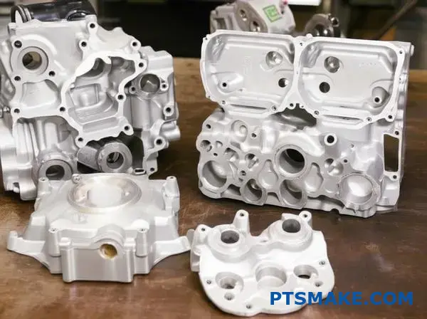
What post-casting finishing options are available and why?
A raw casting is rarely the finished product. Post-casting processes are essential. They turn a rough part into a functional, finished component.
These steps ensure the part meets exact specifications. They also improve its appearance and durability. Let’s explore a catalogue of common options for your project.
| Process | Primary Goal |
|---|---|
| Trimming | Remove excess material |
| Machining | Achieve tight tolerances |
| Coating | Add protection & color |
This ensures every detail, from dimensions to surface feel, is perfect.
After casting, parts require refinement. The specific processes depend entirely on the final application’s requirements. We categorize them into two main types: material removal and surface treatment.
Material Removal and Preparation
First, we must remove any unwanted material left from the casting process.
Trimming and Grinding
This is the initial cleanup stage. We remove flash, gates, and risers. The goal is to get the part to its basic shape. This step is fundamental for all castings.
Shot Blasting
Shot blasting cleans the surface. It also creates a uniform matte texture. This process is great for preparing a part for painting or coating. It ensures better adhesion.
Achieving Final Specifications
These processes create the final form and features.
Precision Machining
When a design requires tight tolerances that casting cannot achieve, we use CNC machining. This is crucial for features like threaded holes or mating surfaces. It defines the part’s final accuracy. We often use this for high-performance aluminum casting components.
Surface Coatings
Coatings provide protection and enhance appearance. The choice between anodizing8 and powder coating depends on the part’s environment and desired look.
| Feature | Anodizing | Powder Coating |
|---|---|---|
| Material | Aluminum Only | Most Metals |
| Protection | Excellent Corrosion/Wear | Good Chip Resistance |
| Finish | Metallic Sheen | Wide Color/Texture Range |
At PTSMAKE, we help select the optimal finish. This ensures the part performs reliably for its intended lifespan.
Post-casting finishing is not an afterthought. It is a critical phase that defines a part’s final precision, durability, and appearance. Choosing the right combination of processes ensures the component meets all functional and aesthetic requirements for its end-use.
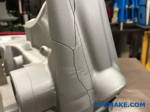
Given a cracked casting, how do you investigate its failure?
Once a crack appears, the investigation begins. It’s not just a defect; it’s a clue. Your first step is to conduct a failure analysis. You must determine if you’re dealing with a hot tear or a mechanical crack. They look different and have very different causes.
Distinguishing Crack Types
Hot tears happen during solidification. Mechanical cracks occur after the casting has cooled. Knowing the difference is key to finding the root cause. This distinction guides your entire investigation.
| Feature | Hot Tear | Mechanical Crack |
|---|---|---|
| Appearance | Ragged, branching, oxidized surface | Clean, sharp, less branching |
| Location | At hot spots, sharp corners | Near stress points, ejector pins |
| Timing | During cooling in the mold | After solidification, during handling |
Investigating Potential Causes
With the crack type identified, you can dig deeper. Each type has its own set of likely culprits. This is where experience in analyzing parts, like we do at PTSMAKE, becomes crucial.
Hot Tear Root Causes
Hot tears are a foundry-level problem. They often relate to the material or the mold design itself. An incorrect alloy composition can create a wide freezing range. This makes the material weak and prone to tearing as it solidifies and shrinks.
Mold restraint is another major factor. If the mold design prevents the aluminum casting from shrinking freely, stress builds up. This stress pulls the weak, semi-solid metal apart, resulting in a tear. This is why we often see them near sharp internal corners. A common sign is an intergranular fracture9 path.
Mechanical Crack Root Causes
Mechanical cracks are post-solidification issues. They happen when external force exceeds the material’s strength. Aggressive ejection forces, misaligned ejector pins, or a poorly designed ejection system can fracture a perfectly good part.
Damage during handling is also common. Dropping, rough stacking, or improper machining setups can introduce cracks. Sometimes, the issue lies in heat treatment. Improper quenching can create massive internal stresses that lead to cracking.
| Crack Type | Potential Cause | Investigation Area |
|---|---|---|
| Hot Tear | Alloy Composition | Material Spectrometry |
| Hot Tear | Mold Restraint | Mold Design Review |
| Mechanical Crack | Ejection Force | Ejection System Check |
| Mechanical Crack | Handling | Post-Molding Process Audit |
| Mechanical Crack | Heat Treatment | Review Heat Treat Cycle |
To solve casting failures, you must first correctly identify the crack type. Hot tears point to material or mold issues. Mechanical cracks suggest problems with ejection, handling, or heat treatment. This distinction is the foundation of an effective failure analysis.
Partner with PTSMAKE for Your Next Aluminum Casting Project
Looking for a reliable aluminum casting solution? Trust PTSMAKE’s expertise and commitment to quality. Get a fast, accurate quote tailored to your project needs—send your inquiry today and experience top-tier precision, consistent results, and responsive support from prototype to production!

Discover how this property directly impacts the final quality and integrity of your cast aluminum parts. ↩
Learn how this specific melting behavior impacts casting fluidity and final part properties. ↩
Explore how this temperature gap influences casting integrity and final part strength. ↩
Learn how upfront tooling investment impacts your final per-part price across the production run. ↩
Learn how this value determines a part’s ability to resist being pulled apart. ↩
Explore how microscopic examination reveals hidden defect characteristics and ensures material integrity. ↩
Learn how this process removes harmful gases to prevent porosity and improve casting integrity. ↩
Learn how this electrochemical process protects and colors aluminum parts. ↩
Learn how material grain structures influence component strength and failure modes. ↩