Finding the right manufacturing process for complex stainless steel components often feels like navigating a maze of compromises. You need intricate geometries, superior surface finish, and tight tolerances – but traditional machining wastes material, forging limits complexity, and conventional casting sacrifices precision.
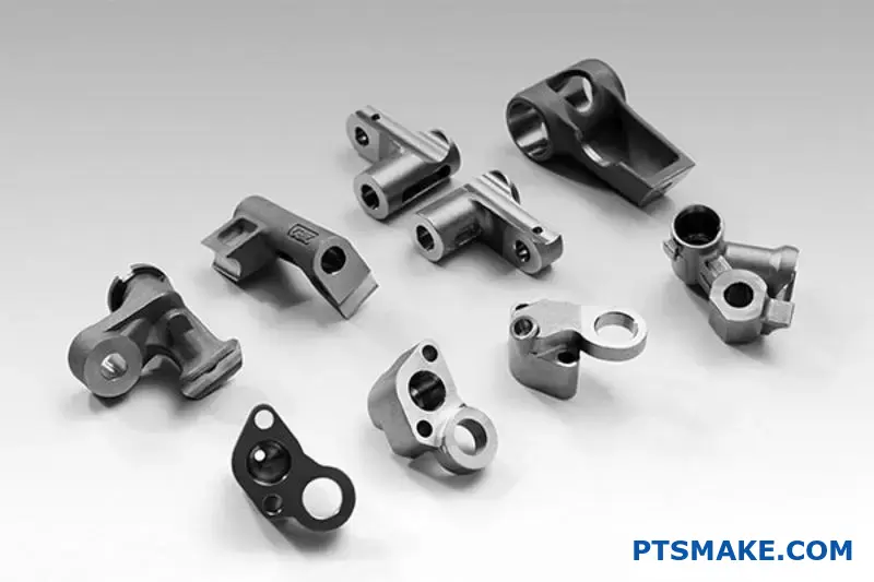
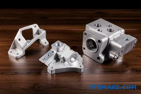
Investment casting for stainless steel delivers near-net-shape parts with exceptional surface finish and dimensional accuracy, eliminating extensive secondary machining while achieving complex internal geometries impossible through other manufacturing methods.
I’ve worked with manufacturers who struggled with these exact challenges for years. They’d watch material costs spiral from excessive machining or settle for simplified designs that compromised functionality. This comprehensive guide walks you through every aspect of stainless steel investment casting – from material selection and process fundamentals to advanced troubleshooting and cost optimization strategies that deliver results.
Why choose investment casting for complex stainless steel parts?
When dealing with complex stainless steel parts, the manufacturing method is critical. The physics behind the process must align perfectly with the material’s nature.
Harnessing Material Fluidity
Stainless steel has excellent fluidity when molten. Investment casting takes full advantage of this. It allows the metal to fill every tiny detail of a complex mold. This creates a near-net-shape part from the start.
Advantages Over Other Methods
Other methods often fall short. Machining is subtractive and wasteful, while forging struggles with intricate internal features. Stainless steel investment casting, however, excels.
| Method | Geometry Freedom | Waste |
|---|---|---|
| Investment Casting | High | Low |
| CNC Machining | Medium | High |
| Forging | Low | Low |
This process is fundamentally suited for turning complex designs into reality. It minimizes secondary operations.
Choosing the right process is about understanding the fundamentals. It’s not just about making a shape; it’s about how the material behaves. For stainless steel, its properties are key.
The Physics of the Flow
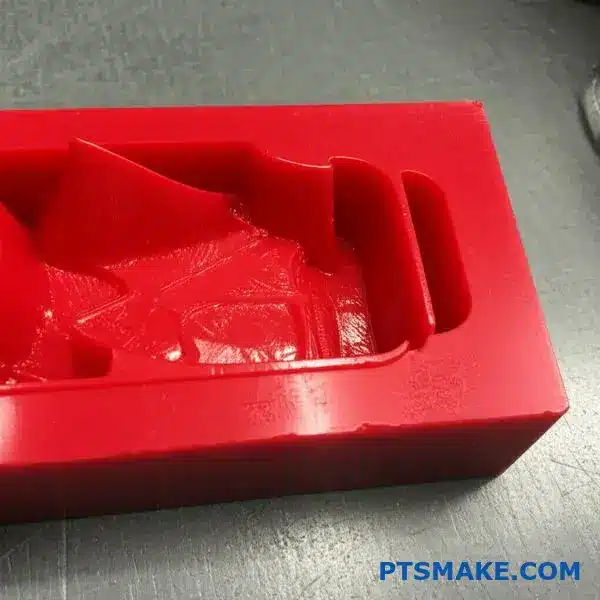
Investment casting uses a ceramic shell made from a wax pattern. When we pour molten stainless steel, it flows smoothly into this pre-heated mold. This controlled flow is essential.
It prevents turbulence and ensures the entire cavity is filled. The slow, uniform cooling that follows minimizes internal stresses. This is a significant advantage over rapid quenching or machining, which can introduce stress points. The process results in parts with excellent isotropic properties1.
Material Integrity and Design Freedom
This method preserves the inherent strength and corrosion resistance of stainless steel. Unlike forging, which aligns grain structure, casting creates a more uniform internal structure.
| Feature | Investment Casting | Forging |
|---|---|---|
| Internal Stress | Very Low | High |
| Grain Structure | Uniform, non-directional | Aligned, directional |
| Design Complexity | High (internal cavities) | Low (solid shapes) |
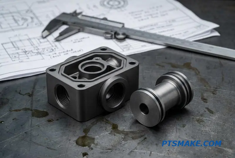
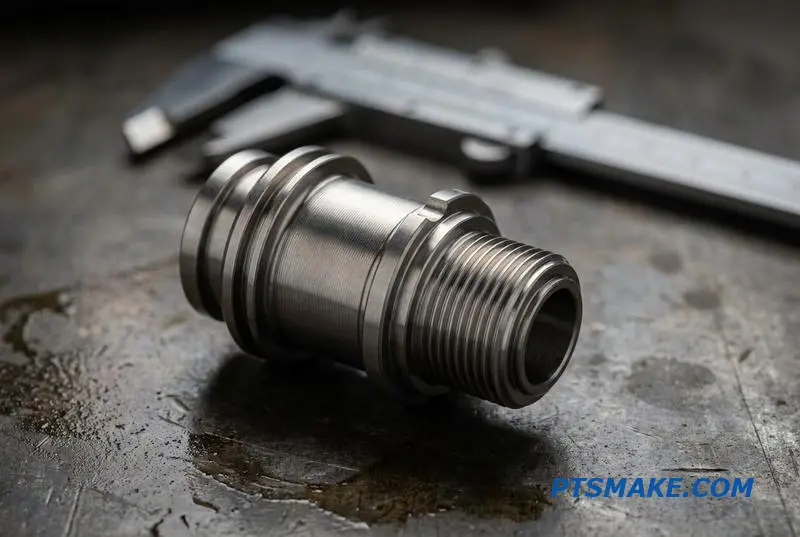
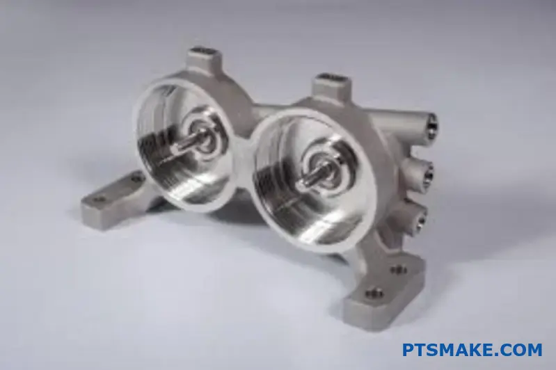
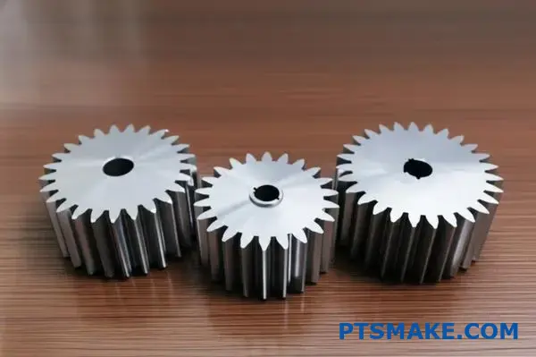
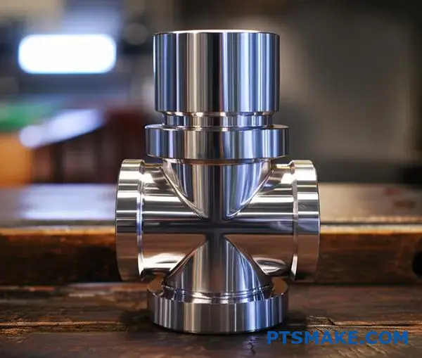
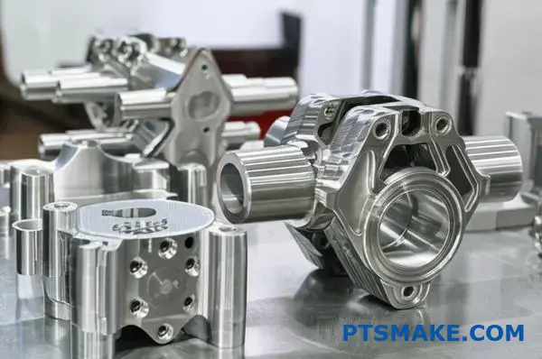
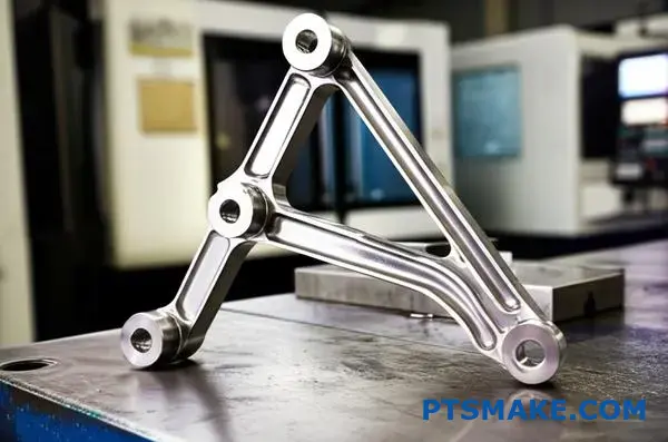
In past PTSMAKE projects, this has allowed us to produce parts like complex valve bodies or turbine blades. These parts are nearly impossible to machine or forge as a single piece.
In essence, investment casting uniquely leverages the fluid dynamics and solidification properties of molten stainless steel. It creates complex, stress-free parts with high integrity, making it a superior choice over machining or forging for intricate designs.
What defines the ‘castability’ of different stainless steel grades?
The chemical recipe of a stainless steel grade is the blueprint for its castability. It dictates everything. At its core, elements like chromium, nickel, and carbon define how the metal behaves when molten.
Consider these common grades.
| Element | Austenitic (304/316) | Precipitation Hardening (17-4 PH) |
|---|---|---|
| Chromium (Cr) | 18-20% | 15-17.5% |
| Nickel (Ni) | 8-14% | 3-5% |
| Carbon (C) | < 0.08% | < 0.07% |
| Other | Molybdenum (in 316) | Copper (Cu), Niobium (Nb) |
Each element plays a distinct role. They directly influence fluidity, cooling behavior, and potential casting defects.
The Elemental Impact on Casting Behavior
The percentage of each element has a profound effect. For instance, higher nickel content, like in austenitic grades (304/316), generally improves fluidity. This makes it easier to fill intricate mold cavities.
However, the combination of elements also creates challenges. The alloy’s composition determines its solidification range2. A wider range can increase the risk of defects like shrinkage porosity and hot tearing, which we must manage carefully.
Carbon’s Dual Role
Carbon content is critical. While it increases hardness, too much carbon can cause problems. It can form chromium carbides during cooling. This depletes chromium from the surrounding matrix, reducing corrosion resistance.
Additives in Specialty Grades
Grades like 17-4 PH contain elements like copper and niobium. These are added for precipitation hardening. But they also alter casting characteristics, requiring specific parameters in the stainless steel investment casting process to achieve sound parts. In our projects at PTSMAKE, we adjust pouring temperatures and cooling rates specifically for these alloys.
A grade’s chemical composition is the primary predictor of its casting performance. Elements like chromium, nickel, and carbon directly influence fluidity, solidification, and susceptibility to defects, requiring tailored process controls for each alloy.
How does the investment casting process inherently control surface finish?
The secret to a flawless surface finish starts with the very first layer. This is the primary slurry coat. Think of it as the foundation of your entire casting.
The Foundation: Primary Slurry Coat
This initial coat is what directly touches your master pattern. Its composition is critical. It determines the final surface texture of the part.
Particle Size Matters
Finer refractory particles in the slurry create a smoother surface. Coarser particles result in a rougher texture. It’s a direct relationship.
| Particle Size | Resulting Surface Finish |
|---|---|
| Fine | Smoother, higher detail |
| Coarse | Rougher, less detail |
This first step is non-negotiable for achieving high-quality results.

The Science Behind the First Coat
From a materials science view, the process is fascinating. The primary slurry is engineered for optimal flow and adherence. It must perfectly coat every feature of the wax pattern.
This slurry contains a fine refractory material, like silica or zircon, suspended in a liquid binder. The binder ensures the particles stick evenly to the non-porous wax surface. The rheology3 of the slurry is tightly controlled. This ensures it flows into tiny crevices without creating air bubbles.
Replicating Fine Details
When the wax pattern is dipped, this first layer captures every minute detail. It’s a negative impression of the master pattern’s surface, down to the microscopic level.
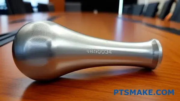
This is especially crucial for complex parts. For example, in stainless steel investment casting, this step ensures features like logos or fine textures are perfectly reproduced. The integrity of this single layer dictates the final outcome.
| Step | Purpose | Impact on Finish |
|---|---|---|
| Slurry Preparation | Mix fine refractory with a binder. | Determines potential smoothness |
| Dipping Pattern | Submerge the wax pattern into the slurry. | Ensures complete coverage |
| Draining | Allow excess slurry to drip off. | Prevents drips and buildup |
| Stuccoing | Apply a fine sand coating to the wet slurry. | Strengthens the initial layer |
This careful, multi-step process for just the first coat is why investment casting provides such superior surface finishes. At PTSMAKE, we have refined this process to ensure consistent, high-quality results for our clients.
The primary slurry coat is foundational. Its fine refractory particles and controlled application directly replicate the master pattern’s details, setting the stage for the final casting’s smooth surface. This initial layer is the key to achieving a high-quality finish.
What physical principle dictates dimensional accuracy in the process?
Dimensional accuracy is a balancing act. It’s dictated by a cascade of thermal events. We must account for three primary sources of variation. Each one introduces a potential error.
The main culprits are wax shrinkage, shell expansion, and metal solidification. While all play a role, one has a much larger impact than the others.
The Sources of Variation
Let’s break them down.
| Variation Source | Cause | Impact Level |
|---|---|---|
| Wax Shrinkage | Cooling of wax pattern after injection | Minor to Moderate |
| Shell Expansion | Heating during furnace firing | Minor |
| Metal Solidification | Cooling of molten metal | Major |
Understanding these is key to precision. It defines the fundamental tolerance limitations of the process.
Why Metal Shrinkage is the Dominant Factor
In past projects, we’ve consistently found metal solidification to be the most critical variable. Wax and shell variations are relatively small and predictable. We can compensate for them fairly easily in the tooling design.
Metal shrinkage is a different beast entirely. It occurs in three stages: liquid, solidification, and solid-state cooling. The total volumetric contraction4 can be significant, often several percent.
This shrinkage dictates the final part dimensions. For materials like stainless steel investment casting alloys, predicting this behavior is crucial.
Managing the Unavoidable
We can’t eliminate shrinkage, but we can manage it. This involves careful design of the gating and riser system. These features act as reservoirs of molten metal. They feed the casting as it cools and shrinks.
This prevents voids and ensures the part solidifies correctly. Our process control at PTSMAKE focuses heavily on managing these thermal dynamics.
| Control Method | Purpose |
|---|---|
| Tooling Compensation | Pre-sizes the mold cavity to account for shrinkage |
| Gating & Riser Design | Feeds molten metal to compensate for volume loss |
| Pouring Temperature Control | Ensures predictable and consistent solidification |
| Cooling Rate Control | Minimizes internal stresses and warpage |
By mastering these elements, we push the boundaries of what investment casting can achieve in terms of precision.
The battle for dimensional accuracy is won by controlling thermal expansion and contraction. Metal solidification shrinkage is the most significant factor, setting the process’s fundamental tolerance limits. Managing it through expert tool design and process control is absolutely essential for success.
What types of defects are traceable to the wax room?
Defects from the wax room directly impact the final metal part. They fall into two main groups: injection issues and assembly errors.
Understanding this link is crucial for quality control. This is especially true for complex stainless steel investment casting projects. Minor wax flaws become major metal defects.
Common Wax Defects and Their Casting Manifestations
| Wax Pattern Defect | Resulting Casting Defect |
|---|---|
| Flow Lines | Surface imperfections, visible lines |
| Sink Marks / Voids | Surface depressions, internal porosity |
| Incomplete Fill | Missing features, incomplete casting |
| Poor Assembly | Dimensional inaccuracies, distortion |
These issues are why rigorous process control in the wax room is non-negotiable for us at PTSMAKE.
The Direct Link: From Wax Flaw to Metal Scrap
The translation of a wax defect to a metal defect is almost one-to-one. A wax pattern is the blueprint for the final casting. Any imperfection is faithfully replicated.
Injection-Related Issues
Think of wax flow lines. They are subtle marks on the wax surface. During shelling, the ceramic slurry captures this texture. The molten metal then fills this mold, creating the same line on the final part.
Similarly, sink marks in the wax pattern create depressions. When the metal is poured, it fills these depressions, resulting in unwanted indentations or even internal voids. This can lead to issues like shrinkage porosity5 if the volume isn’t properly compensated.
Assembly-Related Errors
Assembly defects are often more severe. If wax components on a tree are misaligned, the final cast parts will be dimensionally incorrect. This could mean a part is completely out of tolerance.
A weak or cracked weld during wax assembly is another risk. This can break during shell dipping. The result is a lost part or an inclusion in another part, leading to scrap. Careful assembly is key to ensuring the integrity of the entire casting tree. At PTSMAKE, our technicians are trained to spot and prevent these critical errors before they escalate.
Wax room errors, from injection flaws like flow lines to assembly mistakes, directly create final casting defects. These issues cause surface blemishes, internal voids, and critical dimensional inaccuracies, highlighting the need for strict process control from the very first step.
How do different shell-building systems (e.g., colloidal silica vs. ethyl silicate) compare?
Choosing between colloidal silica and ethyl silicate is a critical decision. This choice directly impacts your project’s timeline, budget, and final quality.
Each system has unique strengths and weaknesses. We will compare them based on key operational parameters. This includes drying time, shell strength, cost, and environmental safety.
Let’s break down the core differences.
| Feature | Colloidal Silica | Ethyl Silicate |
|---|---|---|
| Safety | Safer (water-based) | Hazardous (alcohol-based) |
| Cost | Generally lower | Higher |
| Strength | Good | Excellent |
| Complexity | Best for simpler parts | Ideal for complex parts |
This comparison helps clarify which system fits your specific needs.
The right binder system is crucial for successful investment casting. At PTSMAKE, we evaluate these factors for every project to ensure optimal results. The details matter, especially for high-precision components.
Drying Times and Throughput
Colloidal silica shells dry as water evaporates. This is a slower, more controlled physical process. It requires more time between coats.
Ethyl silicate systems rely on a chemical gelling action. The binder hardens through hydrolysis6, a chemical process. This is much faster, significantly cutting down the shell-building cycle and increasing throughput.
Shell Strength and Part Integrity
Ethyl silicate produces shells with superior green and fired strength. This strength is vital for casting large parts or alloys that are particularly demanding. It minimizes the risk of shell cracking during handling and pouring.
Colloidal silica offers perfectly adequate strength. It is a reliable choice for most standard stainless steel investment casting applications, especially for small to medium-sized parts with less complex geometries.
Cost and Environmental Impact
Here, the systems differ greatly. Colloidal silica is water-based, non-flammable, and has minimal environmental impact. This makes it safer and easier to handle.
Ethyl silicate is alcohol-based. It releases flammable vapors (VOCs), requiring specialized ventilation and safety protocols. This adds complexity and cost to the operation.
| Parameter | Colloidal Silica System | Ethyl Silicate System |
|---|---|---|
| Drying Mechanism | Evaporation (Physical) | Chemical Reaction |
| Drying Time | Slower (2-4 hours/coat) | Faster (1-2 hours/coat) |
| Green Strength | Moderate | High |
| Fired Strength | Good | Excellent |
| Environmental Impact | Low (water-based) | High (VOC emissions) |
| Worker Safety | High | Requires special handling |
| Suitability | General parts, less complex | Intricate, thin-walled parts |
In short, the decision involves a clear trade-off. Colloidal silica is safer and more cost-effective for standard parts. Ethyl silicate offers superior strength and speed, which is essential for complex or demanding geometries, but it comes with higher operational costs and safety requirements.
What are the structural classifications of porosity defects?
Porosity isn’t a single problem. It’s a category of defects. Understanding its structural classifications is the first step to fixing the root cause. At PTSMAKE, we categorize them into three main types.
Each type has a unique signature. This helps us trace it back to a specific process issue. Identifying the correct type is crucial for effective problem-solving.
Below is a quick overview of these classifications.
| Porosity Type | Typical Shape | Common Cause |
|---|---|---|
| Gas Porosity | Spherical, Smooth | Trapped Gas |
| Shrinkage Porosity | Angular, Jagged | Inadequate Feeding |
| Microporosity | Fine, Networked | Solidification Issues |
This simple breakdown helps us quickly diagnose potential problems.

To truly solve porosity, we need to dig deeper into each classification. Each tells a different story about what went wrong during the manufacturing process. This diagnostic skill is key to consistent quality.
Gas Porosity
Gas porosity appears as smooth, generally spherical voids. You can find them near the top surface of a casting or scattered throughout.
The root cause is simple: trapped gas. This gas can come from moisture in the mold, air mixed in during turbulent filling, or gases released from the material itself as it cools.
Shrinkage Porosity
This type looks very different. Shrinkage voids are jagged and angular. They often form a branching, tree-like pattern.
They appear in areas that solidify last, like thick sections or junctions. This happens when there isn’t enough molten material to fill the space left as the part cools and shrinks. This is a common challenge in processes like stainless steel investment casting. Preventing it requires careful mold design.
Microporosity
Microporosity is the trickiest to spot. It consists of very fine, interconnected voids. These are often invisible to the naked eye.
This defect occurs when solidification happens over a wide temperature range, trapping tiny pockets of vacuum in the interdendritic7 regions. It’s a subtle but critical flaw.
| Defect Feature | Gas Porosity | Shrinkage Porosity | Microporosity |
|---|---|---|---|
| Appearance | Smooth, round bubbles | Ragged, angular cracks | Tiny, networked voids |
| Location | Near surface or dispersed | Thick sections, hot spots | Throughout casting |
| Primary Cause | Entrapped gas/moisture | Insufficient material feed | Slow, wide-range cooling |
Understanding the distinct characteristics of gas porosity, shrinkage porosity, and microporosity is essential. This knowledge allows us to pinpoint the specific root cause in the casting process, leading to a direct and effective solution for producing defect-free parts.
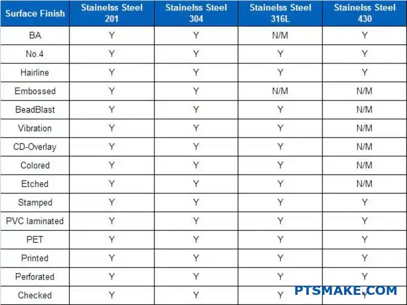
How do surface finish standards (e.g., Ra, RMS) apply to castings?
Specifying the right surface finish for castings is crucial. It’s not just about looks; it affects function and cost. We primarily use Ra (Roughness Average) to define this.
Different processes yield different finishes. An as-cast surface is the baseline. Secondary operations like sandblasting or electropolishing refine it further.
Common Casting Surface Finishes
| Finish Type | Typical Ra (µm) | Description |
|---|---|---|
| As-Cast | 3.2 – 12.5 | The raw surface after casting removal. |
| Sandblasted | 1.6 – 6.3 | A more uniform, matte texture. |
| Electropolished | 0.4 – 1.6 | A very smooth, bright, and clean surface. |
Each level requires specific process controls to achieve consistently.
Achieving a desired surface finish begins long before the part reaches the finishing department. It starts in the shell room. The initial surface quality is determined here.
The first ceramic slurry coats create the part’s surface. The size of the sand, or stucco, used in subsequent layers also plays a role. Finer materials create a smoother as-cast surface.
At PTSMAKE, we control slurry viscosity8 very carefully. This ensures a consistent coating on the wax pattern, which is critical for a uniform initial surface, especially for a high-quality stainless steel investment casting.
Connecting Process to Finish
Process controls in both the shell room and finishing are directly linked. One cannot compensate for major flaws in the other. A poor as-cast surface will require much more finishing work.
| Department | Control Parameter | Impact on Surface Finish (Ra) |
|---|---|---|
| Shell Room | First Coat Slurry | Sets the baseline smoothness. |
| Shell Room | Stucco Grain Size | Finer grains lead to a lower as-cast Ra. |
| Finishing | Blasting Media | Controls texture and final Ra. |
| Finishing | Electropolishing | Significantly reduces Ra for a mirror-like finish. |
In past projects, we’ve found that a well-controlled shell process can reduce finishing time by up to 20%. This lowers costs and improves delivery times.
Achieving the right casting surface finish requires a holistic approach. It starts with precise controls in the shell room and is refined by specific finishing processes. Each step directly impacts the final Ra value and part performance.
How does part geometry influence gating and risering strategy?
Part geometry is not just about looks. It dictates the entire flow of molten metal. A one-size-fits-all gating strategy simply doesn’t exist. We must classify parts to succeed.
We generally group geometries into three main types. Each presents unique challenges for the casting process. Understanding these is the first step.
| Geometry Type | Primary Challenge |
|---|---|
| Thin-Walled Parts | Premature Freezing |
| Heavy-Section Parts | Shrinkage & Feeding |
| Complex Internal Passages | Incomplete Fill & Trapped Air |
This classification guides our initial design. It helps us anticipate problems before they happen.
Adapting the strategy for each geometry is crucial. For thin-walled parts, the metal cools rapidly. We often use multiple gates or fan gates. This ensures the mold fills completely before any section freezes off. The goal is a quick, even fill.
Heavy-section parts are the opposite. Their main issue is shrinkage porosity as the large volume cools. We place large risers close to these sections. This provides a reservoir of molten metal to feed the part. Proper riser design promotes directional solidification9, ensuring the casting is sound. In our experience with stainless steel investment casting, this is critical for robust components.
| Geometry Type | Gating Adaptation | Risering Adaptation |
|---|---|---|
| Thin-Walled | Multiple gates, higher velocity | Often minimal or no risers needed |
| Heavy-Section | Large gates near the section | Large, strategically placed risers |
| Complex Internal | Careful gate placement for flow | Vents are key; risers feed isolated hot spots |
For parts with complex internal passages, the challenge is twofold. We must ensure the metal reaches every corner without trapping air. This requires careful gate placement to lead the flow. More importantly, we design effective vents to allow air to escape.
A part’s shape is a blueprint for our process. Tailoring the gating and risering strategy to its specific geometry—whether thin, thick, or complex—is essential for preventing defects. This customized approach ensures a high-quality, reliable final component.
What inspection methods are available, and what can each detect?
Choosing the right inspection method is critical. It ensures your stainless steel investment casting parts meet exact specifications. Each method has its strengths.
We separate them into two main groups. Non-Destructive Testing (NDT) and Destructive Testing. NDT inspects a part without damaging it. Destructive testing, as the name implies, requires a sample to be destroyed. Let’s look at common NDT options first.
Non-Destructive Testing (NDT)
Visual Inspection (VI)
This is always our first step at PTSMAKE. It’s a quick and low-cost way to spot obvious surface flaws.
Magnetic Particle Inspection (MPI)
MPI is used for detecting surface and slightly subsurface flaws. It only works on ferromagnetic materials.
| Method | Detects | Limitation |
|---|---|---|
| Visual | Surface cracks, porosity, mismatch | Only detects visible, surface-level flaws |
| MPI | Surface/near-surface cracks | Only for ferromagnetic materials |
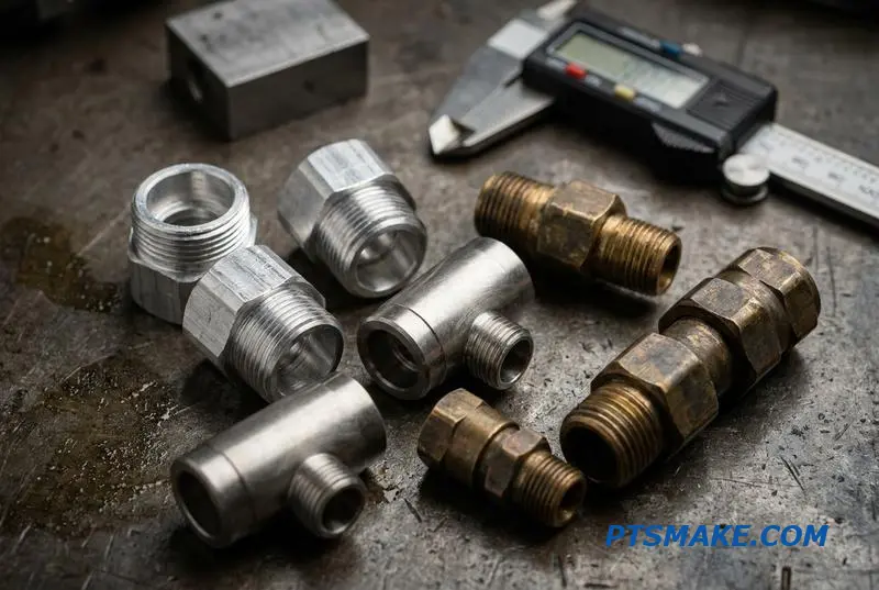
Parts2:
Parts3:
Continuing with NDT, Liquid Penetrant Inspection (LPI) is another key method. It’s excellent for finding surface-breaking defects. This includes tiny cracks or porosity that visual inspection might miss. It works on most non-porous materials. This makes it perfect for austenitic stainless steel, which is non-magnetic.
For internal quality, we rely on Radiographic Testing (RT), or X-ray. It gives us a clear picture of the inside of a casting. We can find internal voids, porosity, or inclusions without cutting the part open. This is vital for high-stress components.
Finally, we sometimes need to verify the exact material composition. While often done destructively, some NDT methods exist. However, the most definitive check is destructive. Chemical analysis via Spectroscopy10 is a method we use. It confirms the alloy grade and elemental makeup. This guarantees the material’s properties match the design requirements for the stainless steel investment casting.
| Method | Best For | Key Limitation |
|---|---|---|
| LPI | Surface-breaking defects (cracks) | Only detects flaws open to the surface |
| X-Ray | Internal voids, porosity, inclusions | Higher cost, requires trained operators |
| Spectroscopy | Verifying chemical composition | Usually a destructive method |
This structured approach ensures comprehensive quality control.
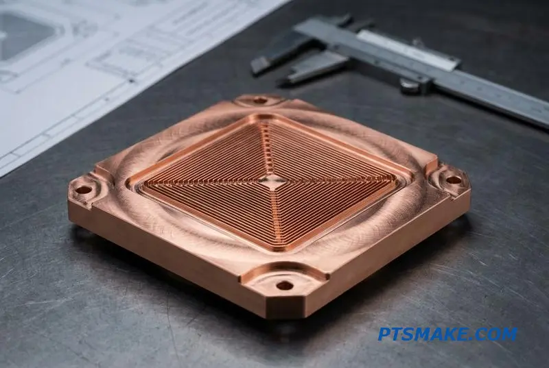
Parts4:
A combination of testing methods ensures complete quality control. Visual and surface methods catch external flaws. Radiography and spectroscopy confirm internal integrity and material composition, providing total confidence in the final stainless steel investment casting parts.
Parts5:
What are the common post-casting operations and their purposes?
After knockout, the raw casting is far from finished. It must go through a precise sequence of operations. Each step methodically refines the part.
This journey transforms a rough component into a high-performance product. It ensures the final piece meets exact specifications.
The Post-Casting Finishing Sequence
The order of these operations is critical. Skipping or reordering steps can compromise the part’s integrity and function. Each stage builds upon the last.
| Operation Stage | Primary Purpose |
|---|---|
| Cutoff | Remove gates, risers, and runners |
| Grinding | Smooth surfaces and remove excess material |
| Sandblasting | Create a uniform surface finish |
| Machining | Achieve final dimensions and features |
This sequence ensures a logical progression from rough to finished.
A Deeper Look at Each Finishing Step
Understanding the purpose of each operation is key to quality control. It’s where we translate a good casting into a great component.
Cutoff and Grinding
First, we physically separate the casting from the gating system. This is done with saws or abrasive wheels.
Next, grinding removes any remaining gate stubs or parting line flash. This initial shaping is crucial for preparing the surface for finer finishing.
Surface and Material Treatments
Heat treatment follows to alter the material’s properties. It can improve strength, hardness, or ductility based on the alloy’s needs.
Sandblasting then cleans the surface. It removes scale and creates a consistent matte texture. This is important for both aesthetics and subsequent coatings.
For materials like stainless steel investment casting, pickling removes surface impurities. This is often followed by passivation11, a chemical process that enhances corrosion resistance by forming a protective oxide layer.
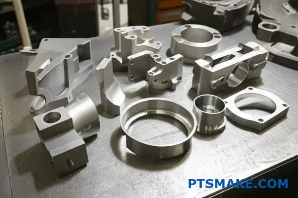
Final Machining
Finally, machining delivers the precision. CNC milling or turning creates features like threaded holes or tight-tolerance surfaces that casting alone cannot achieve. This is the last step to meet the final drawing requirements.
At PTSMAKE, we meticulously plan this sequence. This ensures every part we deliver functions perfectly.
Post-casting operations are not an afterthought; they are an integral part of manufacturing. This multi-step process systematically enhances a raw casting’s properties and appearance, ensuring it meets the stringent requirements of its final application and design intent.
How do tooling design choices impact the entire casting process?
Tooling is the blueprint for your cast part. Every decision made at this stage has a direct impact on the entire process. It’s not just about creating a shape. It’s about engineering a successful outcome.
The Role of Tool Material
The tool’s material determines its longevity and performance. It directly affects the surface finish of every wax pattern produced. A robust tool ensures consistency across thousands of parts.
Strategic Parting Line Placement
The parting line’s location is critical. A poorly placed line creates visible seams. This adds significant time and cost to the final finishing stage. Each choice has a consequence.
| Tooling Decision | Downstream Effect |
|---|---|
| Hardened Steel Tool | Higher wax pattern consistency |
| Poor Parting Line | Increased finishing labor costs |
| Simple Core Design | Faster wax injection cycles |
These connections show how initial planning prevents future problems.
The Importance of Draft Angles
Draft angles are slight tapers on the tool’s surfaces. They might seem like a small detail. But they are crucial for easily removing the wax pattern from the tool.
Without proper draft, patterns can be damaged during ejection. This causes defects like drag marks or distortion. These flaws carry through to the final metal part, often requiring expensive manual correction. This is especially vital for high-precision stainless steel investment casting.
Core Design and Internal Features
Cores create the internal geometries of a cast part. Designing them is a careful balance. They must form the intended feature while still allowing for easy assembly and removal.
A poorly designed core can trap air or cause incomplete filling. This leads to voids or weak spots in the final casting. Proper core design ensures the material fills correctly. It helps manage how the material changes as it cools, a process involving volumetric shrinkage12. At PTSMAKE, we’ve found that optimizing core design can drastically reduce internal defects.
| Design Element | Impact on Wax Injection | Impact on Final Part Quality |
|---|---|---|
| Inadequate Draft | Difficult pattern removal | Surface defects, distortion |
| Complex Cores | Slower cycle times, risk of breakage | Potential for internal voids |
| Good Venting | Complete fill, no trapped air | No porosity, high integrity |
| Strategic Gating | Controlled wax flow | Uniform material properties |
Every design choice links directly to the efficiency and quality of the final product.
Tooling design is not an isolated step. Every choice, from tool material to core design, directly influences manufacturing efficiency, final part quality, and total cost. Proactive planning here is the key to preventing costly problems later in the process.
What are the trade-offs between casting quality, speed, and cost?
In manufacturing, we often face the classic triangle of constraints. You have Quality, Speed, and Cost. The rule is simple: you can pick any two.
This is not a limitation. It is a strategic choice. Understanding this helps manage expectations and achieve project goals effectively.
The Project Management Triangle
This model visualizes the trade-offs. Each side represents one factor. If you shorten one side, you must extend another.
Common Choices
| You Choose | You Sacrifice |
|---|---|
| High Quality & Fast Speed | Low Cost |
| High Quality & Low Cost | Fast Speed |
| Fast Speed & Low Cost | High Quality |
Choosing the right balance is key to a successful project.
Applying the Triangle to Casting
Let’s break down how this works with real-world casting examples. Every decision impacts these three core elements. It’s a constant balancing act.
At PTSMAKE, we guide our clients through these choices daily. It ensures the final product aligns perfectly with their business needs.
Example 1: Improving Quality with Shell Coats
In stainless steel investment casting, the shell is crucial. Adding more ceramic shell coats improves the mold’s strength. This leads to better dimensional accuracy and surface finish.
However, each coat requires drying time. More coats mean a longer production cycle. This directly increases lead time and labor costs. Maintaining the correct slurry viscosity13 is also critical here.
| Action | Quality | Speed | Cost |
|---|---|---|---|
| Add More Shell Coats | ▲ Up | ▼ Down | ▲ Up |
Example 2: The Impact of Automation
Introducing automation, like robotic arms for shell dipping, changes the equation. It’s a significant upfront investment, so the initial cost is high.
However, automation boosts production speed dramatically. Robots work consistently around the clock. This consistency also reduces human error, leading to higher, more repeatable quality over the long term.
It trades a high initial cost for long-term gains in speed and quality.
The project management triangle is a powerful tool. It clarifies that every casting decision involves a trade-off. Understanding this relationship helps you and your manufacturing partner, like us at PTSMAKE, make the best strategic choices for your specific project’s success.
How do you perform a first-article inspection (FAI) effectively?
A comprehensive First-Article Inspection (FAI) is a systematic process. It validates that our production methods create a part exactly to your specifications.
We break it down into key stages. This ensures nothing is missed. It’s about checking every detail against the design intent. This process is crucial.
The core steps are outlined below. Each one validates a different aspect of the manufacturing process, from raw materials to final dimensions.
| FAI Stage | Purpose |
|---|---|
| Documentation Review | Verify all drawings and specs are current. |
| Material Verification | Confirm materials match certifications. |
| Dimensional Layout | Measure every feature on the drawing. |
| Process Validation | Ensure tooling and methods are correct. |
The Foundation: Engineering Drawings
Everything starts with your engineering drawings and specifications. These are the rulebook. We treat them as the single source of truth for the entire inspection.
We confirm we have the latest revision. An FAI on an outdated drawing is a waste of time and resources. This first step prevents major errors downstream.
The drawing’s notes, tolerances, and any special instructions are reviewed meticulously. This includes understanding the full scope of Geometric Dimensioning and Tolerancing (GD&T)14 callouts.
Verifying the Core Materials
Next, we check the material certifications. This confirms the raw material used is exactly what you specified.
For a recent project involving stainless steel investment casting, we traced the material certificate back to the supplier. This ensured the alloy composition and properties were correct before any machining began.
We also verify any required outside processes like heat treatment or plating. Certificates for these processes are collected and reviewed.
The Full Dimensional Layout
This is the most intensive part of the FAI. We measure every dimension, feature, and note on the engineering drawing.
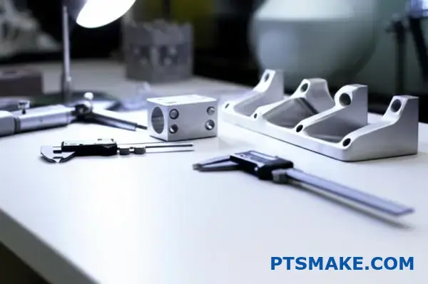
Using tools like CMMs, calipers, and micrometers, we create a "ballooned" drawing. Each dimension is numbered, and the corresponding measurement is recorded next to it.
Here’s a simplified example of what this report looks like:
| Drawing # | Dimension Spec (mm) | Actual Measurement (mm) | Status |
|---|---|---|---|
| 1 | 25.00 +/- 0.05 | 25.02 | Pass |
| 2 | 10.50 +/- 0.05 | 10.58 | Fail |
| 3 | R2.0 | R2.0 | Pass |
This data directly validates the tooling and production setup. A failure indicates a specific adjustment is needed.
A thorough FAI is a multi-step verification. It combines a full dimensional layout, material certification review, and a direct comparison against engineering drawings. This process validates the entire production method, ensuring consistent quality for the full production run.
How do you properly execute passivation for stainless steel castings?
Proper passivation is non-negotiable for performance. It’s not just a cleaning step. It is a crucial chemical treatment. This process removes free iron from the surface.
This creates a protective chromium-oxide layer. It’s the key to corrosion resistance in your parts.
The Two Main Paths
You primarily have two choices for the acid bath. Each has its own best-use case. We choose based on the alloy and application.
Acid Treatment Options
| Acid Type | Primary Use Case | Environmental Impact |
|---|---|---|
| Nitric Acid | Traditional, effective for many grades | Harsher, requires careful disposal |
| Citric Acid | Modern, eco-friendly, excellent for most | Safer, biodegradable |

Proper execution transforms a standard part into a high-performance component. This isn’t just theory. In past projects at PTSMAKE, we have seen improperly passivated parts fail prematurely in the field. The difference is stark.
Controlling the Critical Variables
Success hinges on precision. You cannot simply dip a part and hope for the best. Temperature, acid concentration, and time must be perfectly managed. Small deviations can lead to an incomplete passive layer or, worse, surface etching.
Temperature and Concentration
Maintaining the correct bath parameters is vital. For example, a citric acid bath often runs hotter than a nitric one. But the concentration might be lower. We fine-tune these based on the specific stainless steel grade. It is a delicate balance.
This process involves a controlled chemical reaction, essentially a form of chemisorption15 where the acid helps form the passive film.
Verification is Not Optional
How do you know it worked? You must test it. Waiting for rust to appear is not a strategy. We use verification methods to confirm a passive layer has formed.
| Verification Method | Description | What It Confirms |
|---|---|---|
| Copper Sulfate Test | A solution is applied to the surface. | No copper plating indicates free iron has been removed successfully. |
| Water Immersion Test | Parts are submerged in water for a set time. | No rust formation confirms the presence of a stable passive layer. |
For every batch of stainless steel investment casting parts, these checks are standard procedure.
Executing passivation correctly requires selecting the right acid, precisely controlling temperature and concentration, and verifying the results. This ensures the formation of a robust, protective chromium-oxide layer, which is essential for component longevity and performance in demanding applications.
A customer needs a valve body with a 0.8µm Ra finish. How do you adapt?
Achieving a 0.8µm Ra finish is a serious challenge. It demands a comprehensive plan. You cannot rely on a single process.
At PTSMAKE, we approach this by creating a multi-stage strategy. Each step builds upon the previous one. It starts long before the metal is poured.
Our Step-by-Step Plan
The journey to an ultra-fine finish is systematic. We break it down into distinct phases to ensure control and quality at every point.
| Stage | Key Action | Goal |
|---|---|---|
| 1. Tooling | Mirror Polish | Create a perfect negative mold surface. |
| 2. Casting | Ultra-Fine Slurry | Capture every detail flawlessly. |
| 3. Post-Process | Electropolishing | Refine the surface at a micro-level. |
This structured approach is crucial for stainless steel investment casting.
Deconstructing the Process for a Flawless Finish
Let’s dive deeper into how each step contributes. Simply choosing a final polishing method is not enough. The foundation for the finish is laid from the very beginning.
Stage 1: The Foundation in Tooling
The final part can only be as good as the mold. We start by polishing the tooling surface to a mirror-like finish, often better than 0.1µm Ra. This ensures the wax pattern is nearly perfect before the casting process even begins.
Stage 2: Precision in Casting
The primary ceramic slurry is critical. We use an ultra-fine zircon flour mixed with a colloidal silica16 binder. This captures the minute details from the polished wax pattern. Controlled, robotic shell dipping ensures a uniform layer, preventing any surface imperfections from forming. This is where precision in stainless steel investment casting truly shines.
Stage 3: The Final Polish
After casting, the part is already very smooth. However, to get from a good finish to a 0.8µm Ra finish, a secondary operation is necessary.
| Operation | Mechanism | Impact on Ra |
|---|---|---|
| Electropolishing | Anodic dissolution | Removes microscopic peaks |
| Lapping | Abrasive slurry | Mechanically flattens surface |
| Buffing | Abrasive compound | Smooths and creates luster |
Based on our tests, electropolishing provides the most uniform and consistent result. It chemically removes a microscopic layer of material, effectively leveling the surface peaks without mechanical stress.
Achieving a 0.8µm Ra finish requires a meticulous plan. It’s a chain of precision, from mirror-polishing the tool to controlled shell dipping and finishing with advanced secondary operations like electropolishing. Each step is essential to the final outcome.
A batch of 17-4 PH castings fails hardness tests after heat treatment. Investigate.
When a batch of 17-4 PH castings fails hardness tests, it’s a critical issue. We immediately initiate a systematic investigation. Guesswork isn’t an option.
Our diagnostic process focuses on four primary areas. We check the heat treatment parameters. We verify equipment calibration. We review the raw material certification. Finally, we analyze the part’s surface condition. This methodical approach quickly pinpoints the root cause.
Our Investigation Checklist
| Step | Area of Focus | Key Question |
|---|---|---|
| 1 | Heat Treatment | Were time and temperature correct? |
| 2 | Furnace | Is the equipment properly calibrated? |
| 3 | Material | Does chemistry meet specifications? |
| 4 | Surface | Was the surface compromised? |
Our diagnostic methodology is straightforward but rigorous. We start by pulling the heat treatment charts. We compare the recorded furnace cycle against the required specifications for 17-4 PH. Even small deviations can cause major problems.
Heat Treatment Parameter Review
We often see issues with the aging cycle. For an H900 condition, the parameters are precise.
| Parameter | Specification (H900) | Potential Error |
|---|---|---|
| Temperature | 482°C (900°F) | Too high or too low |
| Time | 1 hour | Insufficient soak time |
Next, we check the furnace calibration records. An uncalibrated thermocouple can report the wrong temperature. This means the actual treatment conditions are incorrect, even if the charts look perfect. It’s a surprisingly common oversight.
We then scrutinize the material test report (MTR) from the supplier. The chemical composition, especially copper content, is vital for proper precipitation hardening in 17-4 PH. An off-spec batch of raw material is a serious possibility.
Finally, we examine the castings for surface decarburization17. This can occur during the shell firing of stainless steel investment casting molds. It results in a soft surface layer, leading to failed hardness tests. Corrective actions include re-heat treating if possible, quarantining the batch, and auditing the supplier.
A systematic investigation is crucial. By meticulously checking heat treatment records, furnace calibration, material chemistry, and surface condition, we can efficiently identify the root cause of hardness failures and implement effective corrective actions to prevent recurrence.
Design a casting process for a part with both thick and thin sections.
Designing a casting process for parts with varied sections is a common challenge. The core problem is differential cooling. Thin sections cool fast, while thick sections cool slowly. This imbalance can cause serious defects.
The Integrated Solution
A single fix is rarely enough. At PTSMAKE, we combine multiple techniques. This integrated approach ensures part integrity. It addresses issues from filling to final solidification.
| Section Type | Cooling Rate | Common Defects |
|---|---|---|
| Thin | Fast | Misruns, Cold Shuts |
| Thick | Slow | Shrinkage, Porosity |
This strategy is key for consistent quality. It prevents costly rework and scrap.
Advanced Gating and Risering
Your gating system is more than a pathway for metal. It’s a tool to control flow and temperature. We strategically place gates to feed the thickest sections last. This ensures they have a supply of molten metal as they cool.
Risers are critical reservoirs. For thick sections, we use insulated sleeves. These keep the riser metal molten longer. Chills, which are pieces of metal or graphite, are placed in the mold. They pull heat away from thick areas, accelerating cooling to match the thin sections.
Precise Pouring and Mold Control
Pouring temperature is a critical variable. A few degrees can change everything. We precisely control this to ensure the metal has enough fluidity to fill thin sections. But it can’t be so hot that it increases shrinkage in thick ones.
For complex parts, especially in stainless steel investment casting, we may adjust the shell itself. A thicker shell around a thin section can act as an insulator. This slows its cooling. Slower cooling can influence the dendritic growth18 during solidification.
| Technique | Primary Function | Target Defect |
|---|---|---|
| Chills | Accelerate local cooling | Shrinkage Porosity |
| Insulated Sleeves | Keep riser metal molten longer | Shrinkage Porosity |
| Temperature Control | Balance fluidity and solidification time | All defect types |
| Shell Adjustments | Insulate or cool specific areas of the part | Misruns, Cracking |
An integrated casting strategy is crucial for parts with varying thicknesses. Combining advanced gating, risers with chills or sleeves, and precise temperature control ensures uniform cooling. This approach prevents defects like shrinkage and guarantees complete mold filling for a high-quality final product.
A competitor is 15% cheaper. How do you reduce cost without sacrificing quality?
Facing a cheaper competitor requires a smart plan. We can’t just cut corners. A comprehensive cost-reduction initiative is the answer. It looks at every part of the process.
This means we go beyond simple fixes. We explore deeper opportunities.
Key Focus Areas
We will target several key areas. These include optimizing processes and managing resources better. It is about working smarter, not cheaper.
| Strategy | Impact Area | Potential Savings |
|---|---|---|
| Process Tuning | Yield & Waste | High |
| Automation | Labor & Consistency | Medium |
| Sourcing | Material Costs | High |

A Deeper Dive into Comprehensive Cost Reduction
A successful cost-reduction plan is multi-faceted. It requires a holistic view of the entire production line. Simply asking for a discount from suppliers is not enough. True, sustainable savings come from internal optimizations.
Manufacturing Floor Innovations
Optimizing gating yield is a crucial first step. It directly reduces metal scrap and rework time. In our experience at PTSMAKE with stainless steel investment casting, improving yield by even a few percent has a significant impact on final part cost.
We also examine shell material consumption. Can we reduce layers without compromising strength? Based on our tests, reducing shell layers can cut both material cost and furnace time. Automating finishing processes like grinding also reduces manual labor.
Energy and Material Strategy
Energy is a major operational expense. For furnaces, achieving perfect Stoichiometric combustion19 is key. This ensures maximum heat from the minimum amount of fuel, cutting energy bills significantly.
Finally, renegotiating material prices is essential. We use our long-term partnerships and volume commitments to secure better rates without sacrificing material quality.
| Initiative | Primary Goal | Secondary Benefit |
|---|---|---|
| Gating Yield Optimization | Reduce Scrap | Faster Cycle Times |
| Shell Material Reduction | Lower Material Cost | Reduced Energy Use |
| Automated Finishing | Cut Labor Costs | Improved Consistency |
| Furnace Tuning | Lower Energy Bills | Reduced Emissions |
This systematic approach ensures we lower costs while maintaining, or even improving, the quality our clients expect.
A holistic strategy is key to reducing costs effectively. By optimizing yield, materials, automation, and energy, you can lower expenses significantly without compromising the quality your customers rely on. This approach builds long-term resilience.
A medical implant requires full traceability. How do you implement this?
Designing a complete traceability system is crucial. It must cover every step. This ensures patient safety and regulatory compliance.
At PTSMAKE, we build systems from the ground up. We start with raw materials. The system tracks everything until the final product ships.
Unique Part Marking
Every single implant needs a unique identifier. This is often a laser-etched serial number. It’s the foundation of individual part tracking.
Material Batch Control
We control all materials used in the process. This includes the wax for the pattern. It also includes the slurry for the ceramic mold.
| Material | Control Method | Purpose |
|---|---|---|
| Steel Alloy | Heat Number Tracking | Links to material certs |
| Investment Wax | Batch Number | Monitors consistency |
| Ceramic Slurry | Mix ID & Date | Ensures shell integrity |
This level of control prevents quality issues.
Documenting Process Parameters
A traceability system is more than just material tracking. It’s about documenting the entire journey of a part. Every step must be logged.
For a complex process like stainless steel investment casting, this is vital. We link every action back to the unique part identifier.
The Digital Thread
We create a "digital thread" for each part. This connects all production data. It ensures nothing gets lost. Think of it as a part’s digital birth certificate.
This includes furnace temperatures and cooling times. It also includes chemical bath compositions. All data is time-stamped and logged.
Linking Certifications and Testing
The final piece is linking all records. This means material certifications from the supplier. It also includes internal checks.
And crucially, it includes results from Non-Destructive Testing20. These tests verify the part’s integrity.
| Record Type | Linked Data | Example |
|---|---|---|
| Material Cert | Heat Number | Chemical composition analysis |
| Process Log | Serial Number & Timestamp | Furnace temperature profile |
| NDT Report | Serial Number | X-ray or ultrasonic scan results |
| Final Inspection | Serial Number | Dimensional and visual checks |
This linked system provides a complete history. If an issue ever arises, we can trace it back to the exact cause. It’s about total accountability.
A truly complete traceability system links a unique part ID to its entire manufacturing history. This includes raw material batches, process logs, and all testing certifications. This creates an unbroken chain of data for ultimate accountability and patient safety.
Unlock Stainless Steel Investment Casting Solutions with PTSMAKE
Need unbeatable quality, fast turnaround, and full traceability for stainless steel investment castings? Partner with PTSMAKE today—send us your inquiry for a custom quote and experience precision manufacturing that exceeds your expectations from prototype to full production.

Learn how uniform material properties in all directions impact part performance and reliability. ↩
Explore our guide on how this metallurgical property impacts final casting quality and integrity. ↩
Explore how slurry flow properties directly impact casting precision. ↩
Learn the principles of metal solidification and its effect on final part integrity. ↩
Learn how this common casting defect forms and discover effective prevention strategies. ↩
Understand how this chemical reaction creates stronger molds for high-precision investment casting. ↩
Discover how the micro-level solidification process creates these nearly invisible yet damaging voids. ↩
Learn how this critical property affects the surface texture and integrity of your final cast part. ↩
Discover how controlling the cooling path is key to creating a solid, defect-free casting. ↩
Learn more about how this method ensures material composition and quality. ↩
Discover how this chemical process dramatically improves corrosion resistance. ↩
Explore our guide on managing material shrinkage for better casting outcomes and higher-quality parts. ↩
Learn how this property impacts your final part’s surface finish and strength. ↩
Learn how GD&T ensures your part’s form, fit, and function meet design intent. ↩
Learn the molecular science behind how this protective passive layer actually forms on the surface. ↩
Discover how this key binder is essential for creating ultra-smooth surfaces in precision casting. ↩
Understand how this carbon loss process can impact your part’s surface integrity. ↩
Understand how metal crystals form to better diagnose and prevent microscopic defects in your cast parts. ↩
Learn how precise fuel-air ratios can significantly cut your energy costs. ↩
Learn about methods used to evaluate material properties without causing damage. ↩