Many engineers struggle with zinc die casting projects that seem straightforward on paper but quickly become complex when tolerances tighten, defects appear, or costs spiral beyond budget expectations.
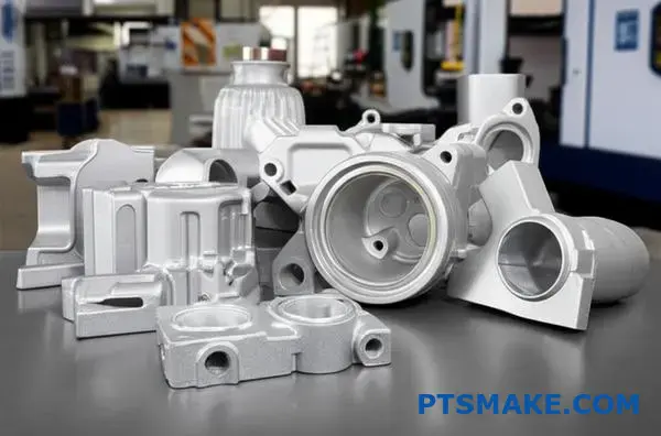
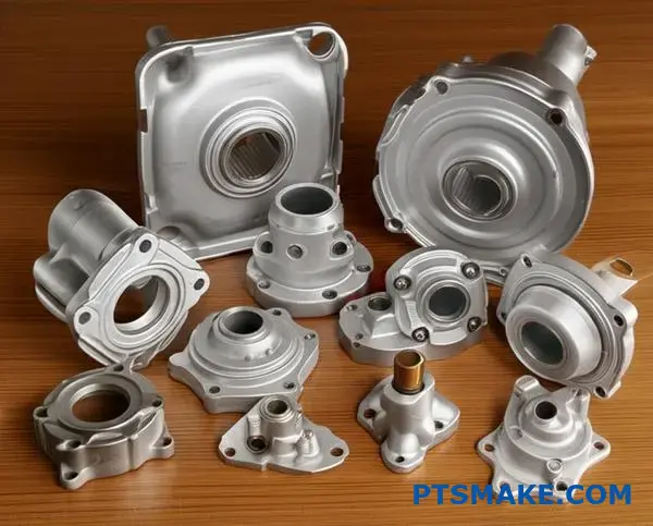
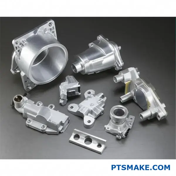
Zinc die casting combines low melting temperatures with excellent dimensional accuracy, making it ideal for high-precision parts in automotive, electronics, and hardware applications where tight tolerances and smooth surface finishes are critical.

This guide covers 14 practical scenarios I encounter regularly at PTSMAKE, from material selection and defect analysis to cost optimization strategies that can save your project both time and money.
Why choose zinc alloys over aluminum for high-precision die casting?
When precision is the top priority, your material choice is critical. While aluminum is popular, zinc alloys often provide superior results. This is especially true for complex, high-precision parts.
The Science of Superiority
The key difference lies in fundamental material properties. Zinc has a much lower melting point and better fluidity. This directly impacts the entire zinc die casting process.
| Material | Typical Melting Point |
|---|---|
| Zinc Alloy (Zamak 3) | ~385°C (725°F) |
| Aluminum Alloy (A380) | ~580°C (1075°F) |
This simple fact has huge implications for production.
How Material Properties Impact Your Project
Choosing a material is more than just specs. It’s about how those properties translate into real-world benefits. In our past projects at PTSMAKE, we’ve seen how zinc’s characteristics create tangible advantages in manufacturing.
Longer Tooling Life
The lower melting temperature of zinc is much gentler on steel molds. It reduces thermal shock and wear. This means the molds last significantly longer, often for over a million cycles. Aluminum’s higher heat is more aggressive, leading to shorter tool life.
Faster and More Efficient Cycles
Since zinc requires less heat, the melting and cooling phases are faster. This results in quicker cycle times. Faster cycles mean higher output and can lead to lower costs per part. Based on our tests, this can improve production efficiency substantially.
| Feature | Zinc Die Casting | Aluminum Die Casting |
|---|---|---|
| Average Tooling Life | 1,000,000+ cycles | ~150,000 cycles |
| Relative Cycle Time | Faster | Slower |
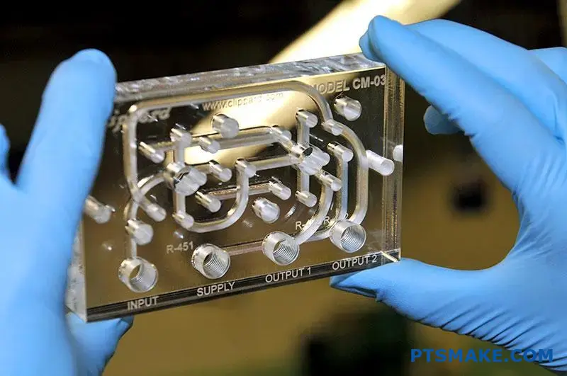
Unmatched Precision
Zinc’s excellent fluidity allows it to fill intricate and thin-walled sections of a mold with ease. This ensures a consistent part structure, free from detrimental intermetallic compounds1 that can form during solidification. This results in tighter tolerances and superior surface finishes.
Zinc’s lower melting point and superior fluidity lead to longer tool life, faster production cycles, and tighter tolerances. These fundamental material advantages make it a top choice for high-precision die casting over aluminum, impacting both quality and cost-effectiveness.
How are common zinc casting defects systematically classified for analysis?
To tackle defects, you first need to organize them. A random approach just won’t work. We use a classification tree to systematically sort issues.
This method helps us pinpoint the root cause much faster. It breaks down defects into clear, manageable groups.
Grouping by Location
Defects can appear on the surface or be hidden inside the part. This is the first, most basic classification.
Grouping by Type
Next, we categorize by type. Is it a dimensional error, like a wrong size? Or a physical flaw, like a crack?
Grouping by Probable Cause
Finally, we link the defect to its likely origin.
| Category | Description |
|---|---|
| Location | Where the defect is found (Surface or Internal). |
| Type | The nature of the defect (Dimensional or Physical). |
| Probable Cause | The likely source of the issue (Process, Material, Tooling). |
This structure prevents us from jumping to conclusions. It creates a logical path for our analysis.
This classification tree is more than a theoretical model. It’s a practical diagnostic tool we use daily at PTSMAKE. It allows our engineering team to communicate clearly and efficiently when addressing a problem.
The Intersection of Categories
A single defect often fits into multiple categories. For instance, "porosity" is an internal (location) physical (type) defect. It can be caused by trapped gas (a process issue).
Understanding these intersections is key. It moves us from simply identifying a flaw to understanding its origin story. This detailed analysis is vital for effective problem-solving in zinc die casting projects.
Another example is a "short shot." This is a surface defect. It is physical in nature and often points directly to a process parameter problem, like insufficient injection pressure. Or it could be a tooling issue, such as a blocked gate. This is why a systematic approach is so crucial. A single defect like intergranular corrosion2 might point to material issues that are harder to spot initially.
| Defect Example | Location | Type | Potential Cause |
|---|---|---|---|
| Blisters | Surface | Physical | Process (Trapped Gas) |
| Warpage | – | Dimensional | Process (Cooling Rate) |
| Cracks | Internal | Physical | Material (Impurity) |
| Flash | Surface | Physical | Tooling (Worn Mold) |
By mapping defects this way, we build a clear picture. This guides us to the right solution, saving time and resources.
This systematic classification transforms defect identification from guesswork into a structured diagnostic process. It is the first step toward effective problem-solving and ensuring consistent part quality for our clients.
What are the practical trade-offs between Zamak and ZA alloys?
Choosing the right alloy is critical. It impacts performance, cost, and even your manufacturing process. It’s a decision we guide our clients through daily at PTSMAKE.
Zamak alloys are the industry workhorses. They are cost-effective and easy to cast.
ZA alloys offer higher strength and better bearing properties. But this performance comes at a price. They often require a different casting method.
Let’s break down the key differences.
| Feature | Zamak 3 | ZA-8 |
|---|---|---|
| Casting Process | Hot Chamber | Hot Chamber |
| Tensile Strength | Lower | Higher |
| Cost | Lower | Higher |
This simple table shows the basic trade-off. You gain strength with ZA-8 but also increase material cost.
The Deeper Dive: Process and Performance
The most significant practical difference is the casting process. Zamak alloys and ZA-8 can use the fast, economical hot-chamber zinc die casting process.
However, higher-aluminum ZA alloys like ZA-12 and ZA-27 must use the slower cold-chamber process. This is because their higher aluminum content is aggressive to the steel components of a hot-chamber machine. This process difference directly impacts cycle times and part cost.
Strength and Bearing Properties
ZA alloys shine in demanding roles. Their superior strength, hardness, and wear resistance make them suitable for replacing machined steel or cast iron parts. ZA-12 and ZA-27, in particular, have excellent bearing properties. This allows you to design parts with integral bearing surfaces, saving on assembly costs. They also have better creep resistance3 than Zamak alloys.
Fluidity and Cost Implications
Fluidity affects how well the alloy fills the die cavity. Zamak alloys generally have excellent fluidity, allowing for thin walls and intricate details.
The table below summarizes the practical trade-offs based on our experience with clients.
| Alloy | Key Advantage | Main Trade-Off | Best For |
|---|---|---|---|
| Zamak 3/5 | Low cost, fast cycles | Lower strength | General-purpose parts |
| ZA-8 | Strongest hot-chamber alloy | Higher cost than Zamak | High-stress applications |
| ZA-12 | Good bearing properties | Cold-chamber process | Bearing and bushing needs |
| ZA-27 | Highest strength | Cold-chamber, harder to cast | Replacing ferrous castings |
The choice is not just about material properties. It is about the total cost of the finished part, including tooling and processing.
The decision between Zamak and ZA alloys hinges on balancing performance needs with budget and manufacturing realities. Zamak is ideal for general applications, while ZA alloys excel where strength and wear resistance are critical, despite their higher processing costs.
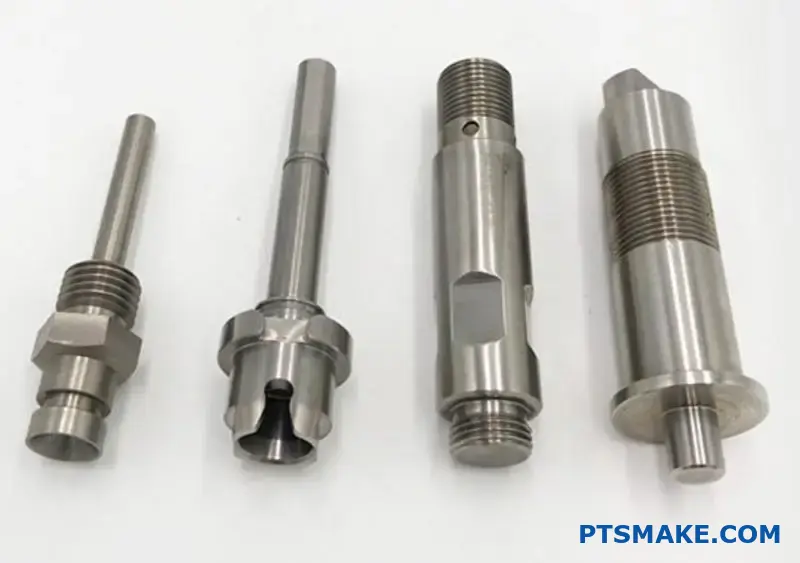
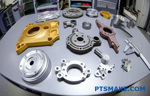
What are the typical categories of secondary operations post-casting?
Once a part leaves the mold, its journey is far from over. Post-casting operations transform a rough casting into a finished component. These steps are critical for function, appearance, and safety.
They ensure the part meets exact specifications. These processes range from basic cleaning to complex surface treatments.
Initial Cleaning and Shaping
The first steps involve removing excess material. Trimming cuts away runners and flash. Deburring smooths sharp edges, which is vital for safe handling and proper assembly.
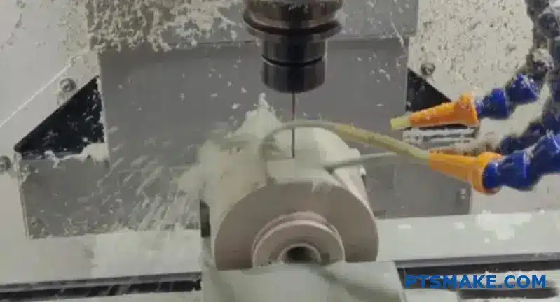
Precision Machining
For features requiring tight tolerances, machining is essential. This includes drilling, tapping, or milling surfaces. These operations achieve the final dimensions that casting alone cannot provide.
Surface Finishing Techniques
This is where the part’s final look and durability are defined. The choice depends on the application’s needs.
| Finishing Type | Primary Benefit | Common Use Case |
|---|---|---|
| Plating | Corrosion Resistance, Aesthetics | Automotive trim, fixtures |
| Painting | Color Customization, Protection | Consumer electronics housing |
| Powder Coating | High Durability, Impact Resistance | Outdoor equipment, industrial parts |
Each step is carefully planned to create a high-quality final product.
Choosing the right secondary operations is a balancing act. It involves considering cost, performance, and aesthetics. Each step adds value but also increases the final part cost and lead time.
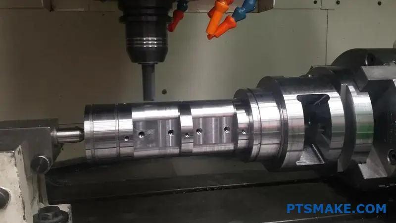
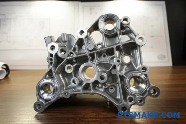
Machining for Critical Dimensions
While casting is great for complex shapes, it can’t always hit tight tolerances. This is where CNC machining comes in. We use it to create precise holes, threads, and flat surfaces that are critical for assembly and function.
In past projects at PTSMAKE, we often machine mating surfaces on zinc die casting parts. This ensures a perfect fit with other components. It prevents leaks or misalignment in the final product.
Selecting the Best Surface Finish
The surface finish is not just about looks. It protects the part from its environment. For example, powder coating provides a tough, durable layer. It’s much more resistant to chipping and scratching than standard paint.
Plating, on the other hand, offers excellent corrosion resistance and a high-end metallic look. The choice often depends on the base material and the product’s intended use. A simple process like passivation can also provide good corrosion resistance for certain materials at a lower cost. Making the right choice early in the design phase is key to managing the project budget effectively. This discussion is a standard part of our process with every client. A bad choice here can compromise the entire product.
For many electronic enclosures, anodizing4 is a popular choice, especially for aluminum. It creates a hard, non-conductive surface.
These post-casting steps are not optional add-ons. They are integral to the manufacturing process, transforming a raw casting into a functional, reliable, and aesthetically pleasing component ready for its final application. Each operation requires careful consideration and expert execution.
How do industry standards (NADCA) structure quality specifications?
NADCA standards create a common language. They cover critical quality aspects for die-cast parts. This removes guesswork between the customer and the caster.
We will focus on three key areas. These are surface finish, porosity, and dimensional tolerances. Understanding them is vital.
Core Quality Pillars
Surface Finish
This defines the visual quality of the part. It ranges from basic to highly polished.
Porosity Control
This standard manages internal voids. It is critical for parts needing strength or pressure tightness.
Dimensional Accuracy
Tolerances ensure the part fits and functions correctly. NADCA provides clear guidelines.
Here’s a quick overview:
| Standard | Purpose | Key Metric |
|---|---|---|
| Surface Finish | Controls aesthetic appearance | Graded levels (e.g., commercial, consumer) |
| Porosity | Manages internal soundness | Porosity grades (1-5) |
| Tolerances | Ensures dimensional fit | Precision vs. Standard Tolerances |
Clear specifications prevent costly rework and delays.
A Deeper Look at NADCA’s Framework
Clear communication is the goal. NADCA’s framework helps everyone agree on what "quality" means for a specific part. It’s not just about numbers; it’s about matching specs to the part’s final use. This is especially true for zinc die casting.
At PTSMAKE, we apply similar principles. We ensure every detail is defined for our CNC and molding projects. This prevents surprises later.
Surface Finish Grades
NADCA separates finishes into categories. "As-Cast" is the standard finish directly from the mold. "Special" finishes require extra steps. These include painting, plating, or polishing. Defining this early impacts cost and production time. The choice depends entirely on the product’s application.
Porosity Levels Explained
Porosity is tiny voids within the metal. NADCA defines levels from 1 (most stringent) to 5 (least stringent). A structural bracket needs a low porosity level. A decorative part can allow for more. This specification directly affects the integrity and performance of the component. Proper metrology5 is used to verify these levels.
Standard vs. Precision Tolerances
Dimensional tolerances control the acceptable variation in a part’s size. NADCA provides two main tiers. Choosing the right one is a balance between function and cost.
| Tolerance Tier | Typical Application | Cost Impact |
|---|---|---|
| Standard | General-purpose parts, non-critical fits | Lower |
| Precision | Tight assemblies, high-performance parts | Higher |
Choosing precision tolerances when not needed adds unnecessary expense. We always help clients make the most cost-effective choice.
NADCA standards create a vital communication tool. By specifying surface finish, porosity, and tolerances, you establish clear, measurable quality targets. This framework removes ambiguity and aligns expectations between the customer and the die caster, ensuring the final part meets all requirements.
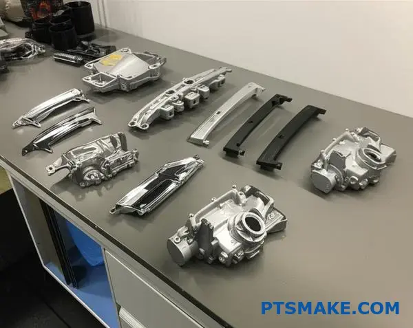
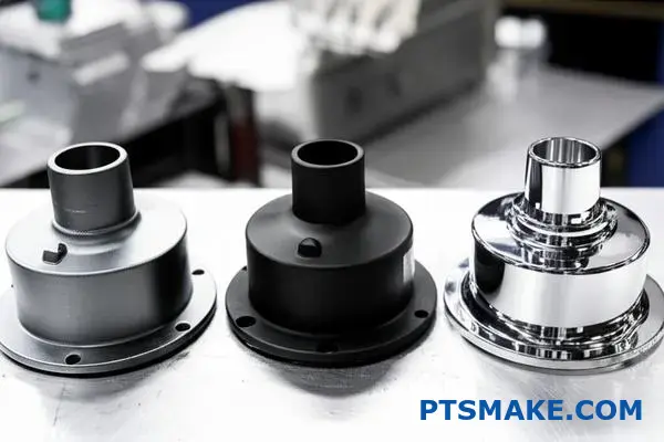
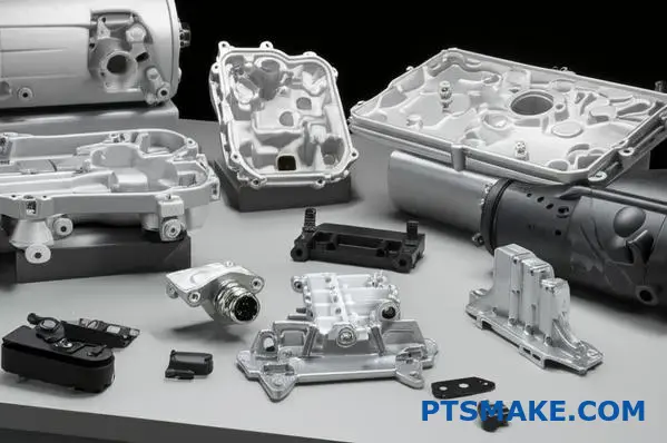
What types of surface finishes are available for zinc castings?
Zinc castings are incredibly versatile. Their final surface can be tailored for many needs. This ranges from function to pure aesthetics. We generally see three main categories.
As-Cast Finishes
This is the most basic finish. It’s the surface directly from the die casting mold. It’s perfect for internal parts where appearance is not a factor.
Protective Finishes
These coatings shield the casting from wear and corrosion. They are vital for parts exposed to the elements or rough conditions.
Decorative Finishes
These are all about looks. They enhance the visual appeal for consumer products. Think shiny chrome on a faucet or a smooth, colored finish.
| Finish Category | Primary Goal | Common Examples |
|---|---|---|
| As-Cast | Cost-Effectiveness | Raw, untrimmed surface |
| Protective | Corrosion Resistance | E-coating, Powder Coating |
| Decorative | Aesthetics & Appeal | Chrome Plating, Polishing |
The lines between these categories can blur. A decorative finish like chrome plating also offers excellent protection against corrosion and wear. It’s all about finding the right balance for your project.
Functional vs. Aesthetic Trade-offs
At PTSMAKE, we help clients navigate these choices. A powder coat provides great durability and color variety. It’s a workhorse finish. But it may not have the premium feel of polished chrome. The decision always comes back to the product’s end-use and market position.
Understanding Key Processes
Different finishes require different methods. E-coating, for example, uses an electrical charge. This deposits a thin, even layer of paint. It’s fantastic for covering every nook and cranny of complex zinc die casting parts.
Chromate conversion coatings are another great protective option. They create a new surface layer through a chemical reaction. This process, a form of Passivation6, makes the zinc less reactive to its environment. It’s an excellent primer before painting or powder coating.
| Finish Type | Best For | Process Complexity | Relative Cost |
|---|---|---|---|
| E-Coating | Complex parts, corrosion | Medium | $$ |
| Powder Coating | Durability, color options | Medium | $$ |
| Chrome Plating | High-end looks, wear | High | $$$ |
| As-Cast | Internal components | Low | $ |
Zinc casting finishes range from as-cast simplicity to decorative and protective coatings. The best choice balances appearance, required durability, and your budget. Each finish offers a unique combination of benefits tailored for specific applications, ensuring your final part performs and looks exactly as intended.
How are the major cost components of a zinc casting structured?
Understanding the cost of zinc casting is simple. You just need to break it down. The total price isn’t a single number. It’s built from four main areas.
These are tooling, raw material, machine time, and finishing. Each one has its own impact on the final quote.
Let’s look at how these parts fit together. This clarity helps you make smarter decisions for your project.
| Cost Component | Description |
|---|---|
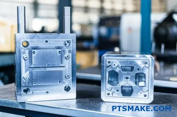
| Tooling | The initial cost of creating the die cast mold. |
| Raw Material | The cost of the specific zinc alloy used. |
| Machine Time | The operational cost for each casting cycle. |
| Secondary Operations | Any post-casting finishing or assembly required. |
Knowing this structure removes surprises from the budget.
Let’s dive deeper into each cost component. Thinking about them separately helps clarify where your budget is going. This breakdown is crucial for optimizing the cost of any zinc die casting project.
Tooling (Amortized Cost)
The mold is a significant one-time investment. We typically amortize this cost over the total production volume. So, for larger production runs, the per-part tooling cost becomes much smaller. A well-designed tool also lasts longer, reducing long-term expenses.
Raw Material (Alloy Cost)
This cost is tied directly to the market price of zinc. The part’s total weight, including runners and overflows, determines the material cost. Efficient mold design, which minimizes scrap, is a key focus for us at PTSMAKE to keep this cost down.
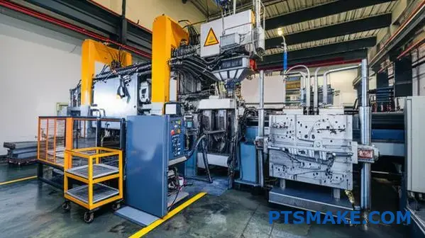
Machine Time (Cycle Cost)
This covers the expense of running the die casting machine. It includes labor, energy, and general maintenance. A faster, more efficient cycle time directly translates to a lower per-part cost. Part complexity and size influence this heavily.
Secondary Operations & Finishing
This is where costs can vary the most. Simple parts may only need flash trimming. Others might require CNC machining, plating, painting, or assembly. Each extra step adds cost. Sometimes, the coating process creates an intermetallic compound7, which requires specific expertise to manage correctly for optimal part performance.
In summary, the total cost of a zinc casting is a blend of four main factors. Tooling is the initial investment, while material, machine time, and secondary operations are ongoing costs. Understanding this structure is key to managing your project budget effectively.
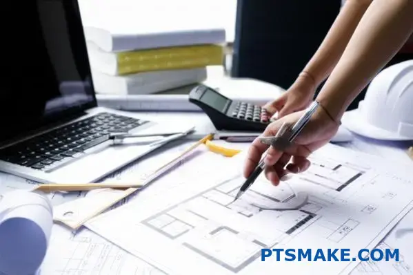
How do you conduct a Design for Manufacturability (DFM) review?
A structured checklist is your best defense against common manufacturing pitfalls. It turns a complex DFM review into a manageable, step-by-step process.
This ensures no critical detail is overlooked before production begins.
Your Essential DFM Checklist
At PTSMAKE, we use a detailed checklist for every project. It helps us catch potential issues early. Here are the core areas we always examine.
| Checklist Area | Key Consideration |
|---|---|
| Wall Thickness | Is it uniform to prevent sink marks? |
| Draft Angles | Are they sufficient for easy mold ejection? |
| Radii & Fillets | Are sharp internal corners avoided? |
| Parting Line | Is its location optimized for aesthetics? |
| Potential Defects | Any features that might trap air or gas? |
This systematic approach saves significant time and money down the line.
Why Each Checklist Item Matters
A checklist is more than just ticking boxes. It’s about understanding the "why" behind each point. This deeper insight prevents costly revisions later. In past projects at PTSMAKE, this understanding has been crucial.
Uniform Wall Thickness
Inconsistent walls cool at different rates. This causes internal stress, leading to warping or visible sink marks on the part’s surface. We always aim for uniformity.
Sufficient Draft Angles
Parts need to be ejected from the mold cleanly. Without adequate draft, parts can stick. This causes scuff marks or even damage during removal. It is a small detail with a big impact.
Strategic Radii and Fillets
Sharp internal corners create stress concentration points. Adding radii helps distribute this stress. This simple change makes the part stronger and less prone to cracking under load.
Parting Line Placement
The parting line location impacts both flash and visual appeal. We analyze the design to place it where it will be least noticeable and easiest to finish. This is key for consumer-facing products.
Complex features can trap air during molding, causing incomplete filling or voids known as porosity8. This is a major concern in processes like zinc die casting.
| Common Issue | DFM Solution |
|---|---|
| Warping | Ensure uniform wall thickness. |
| Ejection Marks | Apply sufficient draft angles (1-2 degrees). |
| Cracking | Add radii to sharp internal corners. |
| Visible Flash | Optimize parting line location. |
This proactive approach ensures the final part meets both functional and aesthetic requirements.
A thorough DFM checklist is a foundational tool for collaboration. It ensures your design is robust, cost-effective, and ready for high-quality production, preventing expensive mistakes before tooling ever begins.
What is the step-by-step process for a First Article Inspection (FAI)?
The FAI process is a structured method. It confirms a new production process meets all engineering specifications.
Initial Production Run
First, we produce a small set of initial parts. This initial run tests the tooling, setup, and machine parameters.
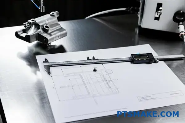
Comprehensive Measurements
Then, a full inspection begins. We measure every feature on the part against the technical drawing. This ensures total accuracy before we proceed.
| Step | Core Action |
|---|---|
| 1 | Produce Initial Sample Parts |
| 2 | Perform Full Dimensional Layout |
| 3 | Conduct Material & Performance Tests |
| 4 | Document Results for Approval |
Measuring parts is just one piece of the puzzle. A thorough FAI goes much deeper to verify every single aspect of the part and the process. It’s about building confidence.
Beyond the Dimensions: Material and Performance
We must confirm the raw material is correct. This involves checking material certifications. Sometimes, it requires independent lab tests to be certain.
For a part like a zinc die casting component, we verify the exact alloy composition.
Performance tests are also vital. We might conduct stress tests or functional checks. This ensures the part performs as designed under real-world conditions. This comprehensive approach prevents failures down the line.
The Importance of Documentation
Every measurement and test result is carefully recorded. A complete dimensional layout9 is central to this process. This data is then compiled into a detailed First Article Inspection Report (FAIR).
At PTSMAKE, we use standard formats like AS9102. This report provides objective evidence that our production process is stable and capable. It is then submitted to you, our customer, for final review and approval. Only after your sign-off does mass production begin.
The FAI process involves producing initial parts, conducting a full dimensional layout, and performing material tests. All data is documented in a report for customer approval, ensuring the entire manufacturing process is validated before full production begins.
How would you justify the investment in a new die versus refurbishing an old one?
Deciding between a new die and refurbishment requires a solid business case. It’s not just about the initial ticket price. We need to look at the Total Cost of Ownership (TCO).
This helps you see the full financial picture. You can then make a decision that benefits you long-term. Let’s break down the key factors.
| Factor | New Die | Refurbished Die |
|---|---|---|
| Initial Cost | Higher | Lower |
| Lifespan | Full, predictable | Limited, variable |
| Performance | Optimized | May have limitations |
| Warranty | Comprehensive | Often limited |
This approach removes guesswork and focuses on data.
The Deeper Dive into Total Cost of Ownership
Looking beyond the initial quote is crucial. A new tool, especially for complex parts like in zinc die casting, often brings significant long-term savings.
At PTSMAKE, we guide clients through this analysis. We compare the immediate cost of refurbishment against the full life-cycle value of a new tool.
Quality and Cycle Time Improvements
A new die is built with the latest technology. This often means faster cycle times and lower scrap rates. Our tests show a new die can improve cycle times by 5-15%.
A refurbished tool might not achieve this. It may carry legacy issues that affect part quality. The long-term cost of a new asset is spread out through Amortization10.
Comparing Long-Term Value
Let’s compare them side-by-side.
| Metric | New Die | Refurbished Die |
|---|---|---|
| Upfront Cost | $X | ~30-50% of X |
| Expected Shots | 1,000,000+ | 150,000 – 300,000 |
| Scrap Rate | <1% | 2-5% (Potentially) |
| Maintenance | Minimal | Higher, less predictable |
| Cost Per Part | Lower over life | Higher over life |
This data shows the initial savings from refurbishment can quickly disappear due to lower efficiency and higher maintenance costs.
The decision isn’t just about the upfront cost. A comprehensive business case focusing on Total Cost of Ownership reveals the true value, factoring in performance, lifespan, and quality. This ensures the best long-term return on your investment.
You must reduce part cost by 10%; what is your comprehensive action plan?
Hitting a 10% cost reduction target requires a multi-pronged strategy. It’s not about one magic bullet. It’s about finding small gains across the entire production process.
We focus on four key areas to achieve this.
Key Areas for Cost Reduction
Cycle Time Reduction
Faster cycles mean more parts per hour. This directly lowers the cost per part. We analyze every step of the process.
Material Savings
Optimizing part design to use less material is a huge win. Thinner walls are a common approach, especially in processes like zinc die casting.
Scrap Rate Reduction
Every scrapped part is wasted money. Tighter process controls are essential to minimize defects and rework.
Efficient Secondary Operations
Post-processing can be a hidden cost center. Streamlining these steps is crucial.
Here’s a simplified look at the potential impact:
| Strategy | Potential Cost Savings |
|---|---|
| Cycle Time Reduction | 2-3% |
| Material Optimization | 3-5% |
| Scrap Rate Reduction | 2-3% |
| Secondary Operations | 1-2% |
By combining these efforts, the 10% goal becomes achievable.
Let’s dive deeper into how this works in practice. A comprehensive action plan means attacking costs from every angle simultaneously. Relying on just one method rarely gets you to a double-digit reduction target.
Optimizing Part Design
We often start with the part design itself. Working with our clients, we review wall thickness. Can we reduce it without compromising structural integrity? For many parts, especially in zinc die casting, this is a quick path to significant material savings. Less material means lower cost.
Enhancing Process Efficiency
Next, we scrutinize the manufacturing process. Reducing cycle time by even a few seconds adds up over a large production run. This could involve optimizing machine parameters or improving mold cooling.
Reducing scrap is equally important. We implement tight process monitoring to catch deviations early. Using tools like Statistical Process Control11 helps us maintain consistency and quality, ensuring fewer parts end up in the scrap bin. This data-driven approach is fundamental.
Finally, we look at everything that happens after the part is made.
| Operation | Before Optimization | After Optimization |
|---|---|---|
| Deburring | Manual, 2 min/part | Automated, 30 sec/part |
| Assembly | Three separate steps | Combined into one step |
| Inspection | 100% manual check | Automated vision system |
Streamlining secondary operations, like combining assembly steps or automating inspection, cuts down on labor costs and time. It’s about being smarter with every single step.
A multi-faceted approach is the only reliable way to achieve significant cost reductions. By addressing cycle time, material use, scrap rates, and secondary operations, you create multiple avenues for savings that combine to meet your 10% target.
How would you adapt your casting process for a new, high-fluidity zinc alloy?
A new, high-fluidity zinc alloy is exciting. It opens doors for complex, thin-walled designs.
However, its nature demands a smaller, more precise process window. We must carefully adjust our parameters. This ensures we harness its benefits without introducing defects.
Adjusting Injection Speeds
With high-fluidity alloys, a slower injection speed is often better. This helps prevent flashing and reduces turbulence inside the mold cavity.
Modifying Melt Temperatures
You can typically lower the melt temperature. This saves energy and reduces stress on the mold. It also minimizes the risk of defects caused by excessive heat.
A careful balance is key for optimal zinc die casting results.
Working with a high-fluidity alloy shrinks our margin for error. The process window becomes tighter. What worked for standard alloys will likely lead to defects here. The key is control. Every parameter must be re-evaluated.
Gate Size and Design Impact
The gate is our primary flow control point. For a very fluid material, a smaller gate might be necessary. This helps to manage the flow rate and pressure more effectively, preventing jetting.
In past projects at PTSMAKE, we’ve found that adjusting gate geometry is crucial.
| Parameter | Standard Zinc Alloy | High-Fluidity Zinc Alloy |
|---|---|---|
| Injection Speed | Higher | Lower & Controlled |
| Melt Temperature | Standard Range | Lower End of Range |
| Gate Size | Standard | Potentially Smaller |
Preventing Common Defects
Flashing is a major risk. The low viscosity12 allows the metal to squeeze into the smallest gaps in the mold. Lowering injection pressure and speed is our first line of defense.
Excessive turbulence is another concern. It can trap air, leading to porosity. A controlled, slower fill helps the metal flow smoothly, ensuring a solid, dense part. This is fundamental to successful zinc die casting.
Adapting to a high-fluidity zinc alloy means tightening process control. By carefully adjusting injection speeds, lowering melt temperatures, and refining gate design, we can prevent defects like flashing and turbulence, ensuring high-quality part production.
Given a complex part drawing, how do you preemptively identify casting risks?
When I receive a complex drawing, I don’t just see lines and dimensions. I perform a mental simulation. This is a core part of our Design for Manufacturability (DFM) process.
I visualize molten metal flowing into the mold. Where will it cool first? Where might air get trapped? This proactive analysis is crucial.
Key Risk Indicators
This mental walkthrough helps me spot potential issues early. It’s about seeing the process, not just the final product.
| Risk Area | Potential Defect |
|---|---|
| Isolated Heavy Sections | Shrinkage Porosity |
| Deep, Thin Ribs | Incomplete Fill |
| Sharp Internal Corners | Stress Concentration |
Applying Advanced DFM for Deeper Insights
My mental simulation is guided by years of experience and DFM principles. I look for specific geometric features that are known to cause problems during casting. It’s about translating the 2D drawing into a 4D process, considering time and temperature.
Isolated Heavy Sections
I immediately look for thick areas surrounded by thinner walls. These "hot spots" cool much slower than the rest of the part. This uneven cooling creates a vacuum, leading to shrinkage porosity. The part essentially pulls itself apart internally as it solidifies.
Deep Ribs and Thin Walls
Deep, thin ribs are a dual threat. First, the molten metal might cool before it can completely fill the feature. This causes a "cold shut." Second, these features can grip the mold tightly, making ejection difficult and potentially damaging the part.
Venting and Trapped Gas
I also trace the likely path of air as metal fills the cavity. Any area where air can’t escape is a major risk. This is a common issue in complex zinc die casting designs. The trapped air results in gas porosity13, which are essentially bubbles within the metal.
| Feature | Primary Risk | Mitigation Strategy |
|---|---|---|
| Thick section | Shrinkage | Add feeders or chills |
| Deep rib | Ejection/Filling | Increase draft angles |
| Unvented corners | Trapped Gas | Add vent channels |
This detailed analysis, done right from the drawing, is how we at PTSMAKE prevent costly rework.
Advanced DFM and mental simulation turn a static drawing into a dynamic process. This foresight allows us to identify and address risks like shrinkage, filling issues, and trapped gas before production even begins, saving time and resources.
How can you use post-processing to salvage parts with minor cosmetic defects?
Deciding whether to salvage a part is an economic choice. You must weigh the cost of rework against the cost of scrapping and remaking. At PTSMAKE, we always perform this analysis first.
Approved procedures can save a part without compromising its function. These fixes are only for minor cosmetic issues. The part’s integrity always comes first.
| Cost Factor | Scrap & Remake | Rework/Salvage |
|---|---|---|
| Material | Full Cost | Minimal (filler, polish) |
| Machine Time | Full Cycle | None |
| Labor | Full Cycle | Rework Time Only |
| Lead Time | Extended | Minimal Delay |
Evaluating Feasibility and Approved Methods
The first step is a clear cost-benefit analysis. Calculate the labor and material costs for the rework. Compare this to the total cost of producing a new part. If rework costs are significantly lower, it’s a viable path.
For this to work, you need specific, approved procedures. These must be documented and repeatable. The goal is a visually acceptable part that meets all functional specifications.
Approved Rework Procedures
We often rely on a few trusted methods for cosmetic fixes. For surface scratches or light blemishes, localized polishing or blending works well. This carefully smoothes the area to match the surrounding finish.
For small pits or voids, especially in parts like zinc die casting components, cosmetic fillers are an option. It’s crucial that the filler is applied before painting or coating. Proper application ensures excellent Substrate Adhesion14 and a seamless final look. These fillers are purely for appearance and should never be used on functional or load-bearing surfaces.
| Rework Method | Best For | Key Consideration |
|---|---|---|
| Localized Polishing | Minor scratches, scuffs | Must not alter critical dimensions or tolerances. |
| Blending | Uneven surface texture | Match the surrounding surface finish perfectly. |
| Cosmetic Fillers | Small pits, voids, dents | Apply before painting; never on functional surfaces. |
Salvaging parts with minor cosmetic defects is feasible if the rework cost is justified. Using approved, documented procedures like localized polishing, blending, or cosmetic fillers ensures the part remains fully functional while meeting aesthetic standards.
Unlock Precision Zinc Die Casting Solutions with PTSMAKE
Ready to solve your zinc die casting challenges? Partner with PTSMAKE to receive fast, expert quotes for your high-precision components. Leverage our decades of experience and advanced capabilities to ensure cost-effective, reliable, and top-quality solutions tailored to your project needs—submit your inquiry today!

Learn more about these microstructures and how they impact material strength and integrity. ↩
Learn how this material defect can compromise part integrity and long-term performance. ↩
Understand how this property impacts the long-term performance of your components under load. ↩
Learn how this electrochemical process improves durability and allows for coloring on metal parts. ↩
Learn more about the science of measurement to ensure product quality. ↩
Learn more about how this chemical process boosts corrosion resistance on metal surfaces. ↩
Learn more about how different material layers interact and affect final part properties and performance. ↩
Learn what causes porosity and how our design guidance helps prevent this critical structural defect in molded parts. ↩
Learn how this measurement report verifies every feature of your part against the original design drawing. ↩
Understand how this financial concept impacts your manufacturing investment decisions. ↩
Discover how data-driven methods can drastically improve your quality and reduce manufacturing waste. ↩
Learn how this fluid property directly influences fill behavior and defect formation. ↩
Discover how trapped air can compromise structural integrity and how proper venting design prevents it. ↩
Learn how proper surface preparation ensures a lasting, high-quality cosmetic repair. ↩