You’re developing a Metal Injection Molding project, but the technical complexity feels overwhelming. From injection parameters to sintering variables, material selection to defect prevention – there are countless moving parts that can derail your manufacturing success.
Metal Injection Molding (MIM) is a powder metallurgy manufacturing process that combines the design flexibility of plastic injection molding with the strength and integrity of wrought metals, producing complex, high-precision parts through feedstock injection, debinding, and sintering stages.

This guide breaks down every critical aspect of MIM manufacturing – from fundamental process stages to advanced troubleshooting techniques. Whether you’re evaluating MIM against CNC machining or optimizing your current production, you’ll find practical solutions to real manufacturing challenges.
What fundamentally defines the injection molding stage in Metal Injection Molding (MIM)?
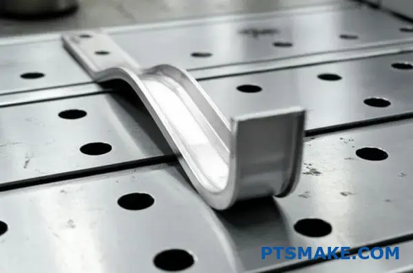
The injection molding stage is where the magic happens. It transforms prepared feedstock into a solid, shaped component. This is known as the "green part."
We achieve this shape using precise heat and pressure. Think of it as a highly controlled shaping process. Every variable matters.
Key Control Variables
The success of this stage hinges on four key parameters. They directly influence the final part’s quality. We must get them right.
| Variable | Physical Impact | Importance |
|---|---|---|
| Temperature | Affects feedstock viscosity and flow | Critical for complete mold filling |
| Pressure | Drives the material into the mold cavity | Ensures part density and detail |
| Injection Speed | Determines how quickly the mold fills | Influences surface finish and defects |
| Hold Time | Maintains pressure as the part cools | Prevents shrinkage and voids |
Getting these parameters right is fundamental. It ensures the integrity of the green part before it moves to the next stages.
The Physics of Mold Filling
The injection molding stage is a delicate dance of physics. We are essentially managing the flow of a very complex material. The feedstock, a mix of metal powder and binder, must flow like a liquid.
This flow must be perfect. It needs to fill every tiny crevice of the mold cavity without any defects. The goal is to create a homogenous green part. This part is fragile but holds the precise geometry for the final product.
The behavior of the feedstock under these conditions is complex. Its rheology1 changes dramatically with small shifts in temperature or pressure. In our projects at PTSMAKE, we’ve found that even a few degrees can make a difference.
Preventing Defects in the Green Part
Controlling the process variables is how we guarantee the green part’s integrity. An incorrect setting can lead to significant problems. These issues can compromise the entire part.
For instance, if the injection speed is too high, it can trap air. If the hold time is too short, the part might have sink marks. We meticulously balance these factors.
| Common Defect | Primary Cause (Variable) | How We Address It |
|---|---|---|
| Short Shot | Low Temperature / Pressure | Increase feedstock temperature or injection pressure |
| Flash | High Injection Speed / Pressure | Reduce speed or optimize clamping force |
| Sink Marks | Insufficient Hold Time / Pressure | Increase hold time and pressure to pack the mold |
| Warping | Uneven Cooling / Temperature | Adjust mold temperature for uniform cooling |
Mastering these variables defines the success of the Metal Injection Molding process.
The injection molding stage uses precise heat, pressure, speed, and time to shape metal feedstock into a "green part." The integrity of this fragile component depends entirely on balancing these variables to ensure complete, defect-free mold filling.
What are the fundamental constraints Metal Injection Molding (MIM) imposes on part design?
Metal Injection Molding (MIM) is not just about the final shape. Success depends on designing for the process itself.
The physics of feedstock flow and sintering creates specific rules. Ignoring them leads to defects and manufacturing headaches.
Core Principles for MIM Design
Wall Thickness and Flow
Uniform wall thickness is crucial. It ensures the mold fills evenly and the part cools consistently. This prevents common issues like sink marks and warpage.
Draft Angles and Radii
Proper draft angles help the "green" part eject from the mold without damage. Generous corner radii reduce stress concentrations, preventing cracks during sintering.
| Design Rule | Reason | Common Defect Avoided |
|---|---|---|
| Uniform Walls | Ensures consistent flow & cooling | Sink marks, warpage |
| Draft Angles | Eases part ejection from mold | Scratches, breakage |
| Corner Radii | Reduces stress concentration | Cracks, weak points |
The most critical phase dictating MIM design is sintering. During this step, the part shrinks significantly to its final density. This transformation must be carefully managed.
Navigating the Sintering Transformation
Accounting for Shrinkage
This shrinkage is generally predictable, around 15-20%. However, complex geometries can cause challenges.
For instance, material flow direction during molding can influence the final dimensions after sintering. This can lead to anisotropic shrinkage2, where the part shrinks differently along various axes. At PTSMAKE, we model this behavior to ensure precision.
The Role of Supports
Just like in 3D printing, some features need support. Not during molding, but during sintering.
Overhangs or long, thin sections can sag or distort under their own weight in the furnace. We design temporary support structures or orient the part to be self-supporting, ensuring it holds its shape.
| Feature | Sintering Risk | Mitigation Strategy |
|---|---|---|
| Large, unsupported spans | Sagging or distortion | Add temporary supports |
| Abrupt thickness changes | Uneven shrinkage, cracks | Gradual transitions, coring |
| Complex internal channels | Trapped gas, distortion | Design for self-support |
Mastering Metal Injection Molding requires designing for the entire process, not just the final part. Adhering to rules for wall thickness, draft angles, and especially sintering shrinkage, is fundamental to achieving a robust, defect-free component that meets specifications.
What are the major categories of Metal Injection Molding (MIM)-compatible metal alloys?
Metal Injection Molding (MIM) supports a diverse range of metal alloys. This flexibility is key to its success. We can group these materials into three main families. Each family has unique properties. This makes them suitable for different applications.
Ferrous Alloys
These are iron-based materials. They are the most common in MIM. They offer great strength and wear resistance at a good cost.
Non-Ferrous Alloys
These alloys do not contain iron as their main component. They are chosen for specific properties. Think light weight or high conductivity.
Specialty Alloys
This group includes materials for extreme conditions. They handle high temperatures, high stress, or high density needs.
Here is a quick overview:
| Alloy Family | Key Characteristics | Common Applications |
|---|---|---|
| Ferrous Alloys | High strength, hardness, cost-effective | Automotive, firearms, industrial tools |
| Non-Ferrous Alloys | Lightweight, corrosion-resistant, conductive | Medical, electronics, aerospace |
| Specialty Alloys | Extreme temperature resistance, high density | Aerospace turbines, defense, medical shielding |
Let’s dive deeper into these alloy families. The right material choice is critical for your project’s success. At PTSMAKE, we guide our clients through this selection process. We match material properties to performance needs.
Ferrous Alloys In-Depth
Ferrous alloys are the workhorses of the MIM industry.
Stainless Steels
We see stainless steels like 17-4PH and 316L used often. 17-4PH is prized for its high strength and good corrosion resistance. 316L is an austenitic3 grade. It offers superior corrosion resistance, making it ideal for medical and marine applications.
Tool Steels
Tool steels are known for exceptional hardness. They are perfect for cutting tools and high-wear components. Their complex shapes are easily achieved with MIM.
Non-Ferrous Alloys In-Depth
These materials solve specific engineering challenges.
Titanium Alloys
Titanium is strong, lightweight, and biocompatible. This makes it a top choice for medical implants. It’s also used in aerospace for its high strength-to-weight ratio.
Copper Alloys
Copper is excellent for electrical and thermal conductivity. We use it for small, complex parts in electronics. Think heat sinks and connectors.
Specialty Alloys In-Depth
When conditions get tough, we turn to specialty alloys. These materials perform where others fail.
| Alloy Sub-Category | Key Property | Typical MIM Application |
|---|---|---|
| Superalloys | High-temperature strength | Jet engine turbine blades |
| Tungsten Heavy Alloys | Very high density | Radiation shielding, vibration damping |
| Cobalt-Chrome (Co-Cr) | Wear resistance, biocompatibility | Orthopedic implants |
These advanced materials push the boundaries of what’s possible with Metal Injection Molding.
In short, MIM technology is compatible with a wide array of metal alloys. These range from common stainless steels to high-performance superalloys. This versatility allows for the creation of precise, complex parts for nearly any industry or application.
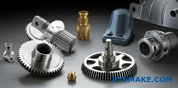
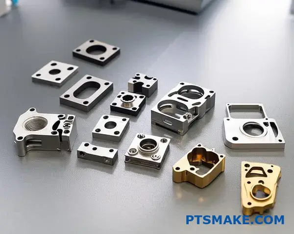
What types of part geometries are ideal for Metal Injection Molding (MIM)?
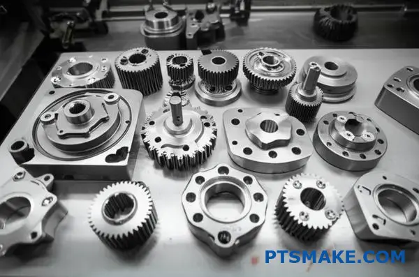
Metal Injection Molding (MIM) is not a universal solution. It excels with a specific class of components where traditional methods fall short.
The Sweet Spot: Small and Complex
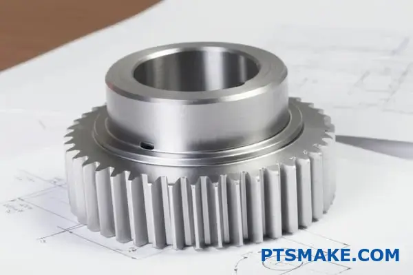
The ideal candidates are typically small, weighing under 100 grams. They feature complex, three-dimensional shapes. These are parts that are often too difficult or costly to produce with machining.
Key Characteristics for MIM
Here’s a breakdown of the ideal features.
| Feature | Ideal for MIM |
|---|---|
| Size | Small, typically < 100g |
| Complexity | High, with intricate details |
| Geometry | Three-dimensional, non-symmetrical |
| Production | High volume runs |
Why Complexity is a Key Advantage
The magic of MIM lies in its ability to handle complexity efficiently. With traditional CNC machining, every complex feature adds time and cost. For MIM, complexity is "free" once the mold is made.
The initial tooling investment is higher. But for high-volume production, the per-part cost drops significantly. This makes it a game-changer for producing thousands of identical, complex parts.
At PTSMAKE, we often work with clients on parts that were previously machined. Shifting to MIM can lead to substantial cost savings without sacrificing quality. This process involves a critical thermal treatment called sintering4 to fuse the metal particles.
Prime Examples of MIM Geometries
Let’s look at some classic examples to understand the ideal fit for Metal Injection Molding.
| Industry | Example Component | Key Geometric Features |
|---|---|---|
| Firearms | Triggers, hammers, sights | Complex internal cavities, fine details |
| Medical | Surgical tools, orthodontic brackets | Tiny, intricate shapes, biocompatibility |
| Electronics | Connectors, heatsinks | Thin walls, complex internal channels |
| Automotive | Sensor housings, lock components | Small gears, threads, undercuts |
Each of these examples would be incredibly difficult or expensive to produce at scale using other methods. MIM makes their production feasible and cost-effective.
In summary, Metal Injection Molding is the perfect solution for small (<100g), geometrically complex parts produced in high volumes. It provides a cost-effective alternative to machining for components with intricate, three-dimensional features, unlocking design freedom.
What are the common types of Metal Injection Molding (MIM) machines?
When discussing Metal Injection Molding, the machine’s drive system is a key factor. It defines how the machine operates. The choice directly impacts project outcomes.
We can categorize them into three main types.
Hydraulic Machines
These are the traditional workhorses. They use hydraulic fluid to generate force. They are powerful and robust.
Electric Machines
These use electric servo motors. They offer superior precision and control. They are also much quieter.
Hybrid Machines
These combine features from both. They might use a hydraulic pump for clamping. But they use an electric drive for injection.
| Machine Type | Primary Power Source | Key Feature |
|---|---|---|
| Hydraulic | Hydraulic Fluid | High Power |
| Electric | Servo Motors | High Precision |
| Hybrid | Mixed | Balanced Performance |
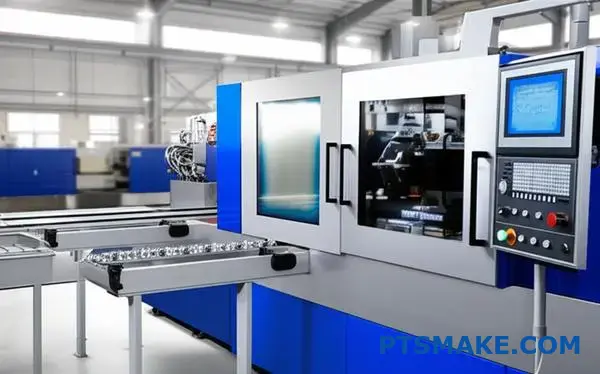
Choosing the right MIM machine is critical. It’s about balancing cost, precision, and efficiency for your specific part. Let’s break down how these machines compare in practice.
Precision and Control
Electric machines are the clear winners here. Servo motors provide exceptional repeatability5 and accuracy. This is crucial for complex parts with tight tolerances, common in medical and aerospace fields.
Hydraulic machines are less precise. Temperature changes in the fluid can affect performance. Hybrid machines offer a good middle ground, often improving on purely hydraulic systems.
Energy Efficiency
This is a major advantage for electric machines. They only consume power when moving. Our internal studies at PTSMAKE show they can use 50-70% less energy than hydraulic models. This significantly lowers operational costs over time. Hydraulic machines constantly run a pump to maintain pressure, wasting energy.
Speed and Maintenance
Hydraulic machines can offer very high injection speeds. However, electric machines often have faster overall cycle times due to parallel movements.
For maintenance, electric machines have fewer components that wear out. There are no hydraulic fluid leaks, filters, or hoses to manage. This results in a cleaner work environment and less downtime.
| Feature | Hydraulic | Electric | Hybrid |
|---|---|---|---|
| Precision | Good | Excellent | Very Good |
| Energy Use | High | Low | Medium |
| Maintenance | High | Low | Medium |
| Initial Cost | Low | High | Medium |
The choice between hydraulic, electric, and hybrid MIM machines depends on your project’s specific needs. Electric machines excel in precision and energy savings, while hydraulic systems offer high power at a lower initial cost. Hybrids provide a balanced approach.
How are common Metal Injection Molding (MIM) part defects categorized?
Understanding Metal Injection Molding defects is key to quality control. The most effective way is to group them by their process origin.
This approach simplifies troubleshooting significantly. It allows us to pinpoint the exact stage causing the issue, saving time and resources.
Defects by Process Stage
We can break down common defects into three main categories based on where they occur in the MIM process.
| Stage | Common Defects |
|---|---|
| Molding | Short shots, flash, weld lines |
| Debinding | Cracks, slumping, blistering |
| Sintering | Distortion, porosity, incorrect dimensions |
This categorization provides a clear roadmap for diagnosing and resolving production issues effectively.
Categorizing defects by their origin is more than just an organizational habit. It is a critical diagnostic strategy. A flaw that becomes visible on a final sintered part may have actually started much earlier in the process. This is why a holistic view is essential.
A Systematic Troubleshooting Framework
For example, a crack discovered after sintering might not be due to a faulty furnace profile. The stress could have been introduced during debinding, where the binder was removed too aggressively. Without proper categorization, you might waste time adjusting the wrong parameters.
At PTSMAKE, our process control involves checkpoints at each stage. This helps us catch and correct deviations before they cascade into bigger problems later on.
The Interconnected Nature of MIM Stages
The MIM process stages are closely linked. A seemingly minor issue in one step can have a major impact on the next.
| Root Cause Stage | Potential Outcome |
|---|---|
| Molding | Inconsistent green part density can lead to distortion. |
| Debinding | Residual binder can cause blistering during sintering. |
| Sintering | Incorrect temperature can result in poor mechanical properties. |
This interconnectedness highlights the importance of rigorous quality control throughout the entire workflow. During sintering, parts densify as atoms bond through a process known as solid-state diffusion6. Any earlier error can disrupt this critical transformation, leading to part failure.
Categorizing Metal Injection Molding defects by their process stage—molding, debinding, and sintering—is crucial for effective troubleshooting. This method helps isolate root causes quickly, ensuring consistent part quality and preventing costly errors from repeating.
What are the available secondary operations for Metal Injection Molding (MIM) parts?
Metal Injection Molding (MIM) is a powerful process, but the part that exits the furnace isn’t always the final product. Secondary operations are often crucial.
We can organize these extra steps by their purpose. Each one solves a specific engineering challenge to meet your final requirements.
For Tighter Tolerances
Machining or grinding refines specific features. This is vital when the as-sintered tolerances of MIM parts aren’t quite enough for your application.
For Enhanced Strength
Heat treatment is used to modify the part’s microstructure. This process can significantly improve hardness, strength, and overall durability.
For Surface Protection
Plating and coatings add a functional or cosmetic layer. This is perfect for improving corrosion resistance, wear resistance, or appearance.
For Precise Dimensions
Coining or sizing is a cold working process. It precisely forms key dimensions, improving dimensional accuracy and surface finish.
| Operation | Primary Purpose |
|---|---|
| Machining/Grinding | Achieve tight tolerances |
| Heat Treatment | Improve mechanical properties |
| Plating/Coating | Enhance surface resistance |
| Coining/Sizing | Refine dimensional accuracy |
Matching the Operation to the Application
Selecting the right secondary operation is a critical decision. The choice depends entirely on the part’s final function and operating environment. It’s not a one-size-fits-all approach.
A gear might need heat treatment for wear resistance. A medical device component may require electropolishing for a smooth, clean surface. We always start with the end goal in mind.
Cost vs. Performance
Every secondary process adds to the final part cost and lead time. It’s a classic engineering trade-off. We often work with clients to analyze if the performance gain is justified.
Sometimes, a minor design modification can eliminate the need for a costly secondary step. This is where early collaboration in the design phase pays off.
For parts requiring a hard surface with a ductile core, case hardening7 is a common and effective method we use. This selective treatment optimizes performance without making the entire part brittle.
Process Considerations
Each operation has its own set of technical considerations. Success depends on understanding how these processes interact with the MIM material and part geometry.
| Operation | Key Consideration | Potential Downside |
|---|---|---|
| Machining | Access to features, material hardness | Increased cost, longer lead time |
| Heat Treatment | Material compatibility, properties | Potential for part distortion |
| Plating | Surface preparation, adhesion quality | Added thickness, hydrogen risk |
| Coining | Part geometry, material ductility | Limited to simpler shapes |
Secondary operations for MIM parts are grouped by their goal. Machining provides precision, heat treatment adds strength, plating protects surfaces, and coining refines dimensions. The right choice balances performance requirements against cost, material properties, and potential process challenges.
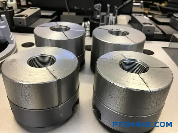
How does Metal Injection Molding (MIM) tooling differ from plastic injection molding tooling?
While the names sound similar, the tools for Metal Injection Molding (MIM) and plastic molding are fundamentally different. The demanding nature of MIM feedstock requires a completely different approach.
MIM tooling must withstand highly abrasive materials. This means using much harder tool steels. Ejection systems also need to be more robust and precise. Finally, the most critical difference is managing the massive part shrinkage that occurs after molding.
| Feature | MIM Tooling Requirement | Plastic Tooling Requirement |
|---|---|---|
| Tool Steel | Hardened, wear-resistant steel | Softer, standard tool steel |
| Ejection | Highly precise and robust system | Standard ejection system |
| Shrinkage | Accommodates 15-25% shrinkage | Accommodates 0.5-5% shrinkage |
Tool Steel: Built for Abrasion
The feedstock in Metal Injection Molding is a mix of fine metal powders and a polymer binder. This mixture is extremely abrasive, far more so than any filled plastic.
Standard tool steels like P20, common for plastic molds, would wear out very quickly.
For MIM, we must use hardened tool steels. This includes materials like D2, M2, or even molds with carbide inserts for extremely high-wear areas. This ensures the tool’s longevity and maintains part accuracy over the production run.
Ejection Systems: Handling Fragile Green Parts
After molding, the MIM part is in its "green" state. It’s incredibly fragile, with a consistency similar to chalk. A standard ejection system would easily break or deform it.
MIM tools require more complex and robust ejection systems. This often involves more ejector pins, carefully placed to distribute force evenly. The ejection motion itself is slower and more controlled to gently push the delicate part out of the cavity without causing damage.
The Shrinkage Factor: Designing a Bigger Part
This is the biggest differentiator. Plastic parts shrink a little, maybe up to 5%. MIM parts, however, shrink dramatically during the final sintering stage—typically between 15% and 25%.
This means the mold cavity must be designed significantly larger than the final part. Calculating this is not simple. The shrinkage is not always perfectly uniform. Factors like part geometry and material flow affect the final dimensions. Mastering this requires deep process knowledge to predict how the part will change, aiming for ideal Isotropic Shrinkage8.
At PTSMAKE, we leverage simulation software combined with our project experience to engineer these complex cavities accurately. This ensures the final sintered part meets the precise specifications our clients require.
In summary, MIM tooling demands much harder, wear-resistant steels. It also requires more precise ejection systems for fragile green parts and, most importantly, expert design to accommodate the massive and complex shrinkage that occurs during the sintering process.
How do you control dimensional variation in Metal Injection Molding (MIM) parts?
Controlling dimensions in Metal Injection Molding parts requires a meticulous, multi-stage approach. It is not about a single magic bullet. It’s about precision at every step.
From the raw material to the final furnace cycle, each phase impacts the final outcome. A small deviation early on can lead to significant variations later.
Key Process Control Points
| Stage | Primary Goal |
|---|---|
| Feedstock Prep | Ensure batch consistency |
| Molding | Create uniform green parts |
| Debinding | Remove binder without stress |
| Sintering | Achieve predictable shrinkage |
This systematic control is how we achieve tight tolerances consistently for our clients at PTSMAKE.
A Deeper Look at Control Actions
Effective control begins long before the part is molded. It starts with the material itself and the tool used to shape it.
Feedstock and Tooling Design
The feedstock must be perfectly consistent. Any variation in the metal powder size, shape, or binder ratio between batches will alter the shrinkage rate. This is the first critical control point.
Simultaneously, tooling design is paramount. The mold cavity is intentionally made larger than the final part. After working with clients, we know it must precisely account for shrinkage, which can be 15-20%.
Molding and Debinding Precision
Once the material and tool are set, we focus on the process. Molding parameters like temperature, pressure, and injection speed are tightly monitored to ensure every "green" part is identical.
The debinding stage carefully removes the binder. This process must be uniform to prevent part distortion. It often includes a controlled thermal pyrolysis9 step, which breaks down the binder before the final sintering phase.
Sintering: The Final Transformation
Sintering is the most critical phase for dimensional control. Here, the part is heated, and metal particles fuse together, causing it to shrink to its final dimensions.
| Sintering Variable | Impact on Dimensions |
|---|---|
| Temperature Profile | Directly controls shrinkage amount |
| Cycle Time | Ensures complete particle fusion |
| Furnace Atmosphere | Prevents oxidation and surface defects |
Strictly managing these parameters ensures the shrinkage is predictable and repeatable, part after part.
Mastering dimensional variation in Metal Injection Molding is a holistic effort. It requires rigorous control over feedstock consistency, precise tool design, and stable parameters throughout the molding, debinding, and sintering stages to ensure final part accuracy.
How do you select the appropriate material for a Metal Injection Molding (MIM) application?
Choosing the right material is crucial for any Metal Injection Molding project. It’s a balance of performance, environment, and cost.
I guide clients with a simple framework. We focus on three key areas. This ensures the final part meets all specifications without over-engineering.
Core Selection Criteria
| Factor | Key Considerations |
|---|---|
| Mechanical Properties | Strength, hardness, wear resistance |
| Environmental Resistance | Corrosion, temperature, chemical exposure |
| Total Cost | Raw material price, processing complexity |
This structured approach helps clarify the trade-offs. It leads to the best material for your specific application.
A Practical Selection Framework
Let’s dive deeper into this framework. It’s about asking the right questions to find the optimal solution for your MIM parts.
Mechanical & Environmental Needs
First, define the part’s job. Does it need high strength and hardness? Or is corrosion resistance the top priority? You can’t always have both at a low cost.
For example, 17-4PH stainless steel offers excellent strength. This comes from its ability to undergo precipitation hardening10. It’s perfect for high-stress components.
In contrast, 316L stainless steel provides superior corrosion resistance. It is often used in medical devices or marine applications. Its strength is lower than 17-4PH.
In past projects at PTSMAKE, we’ve helped clients navigate this choice. A medical tool needs 316L for biocompatibility. A high-wear gear benefits from the hardness of 17-4PH.
Comparing Common MIM Stainless Steels
Here’s a quick comparison based on our test results.
| Property | 17-4PH Stainless Steel | 316L Stainless Steel |
|---|---|---|
| Primary Advantage | High Strength & Hardness | Excellent Corrosion Resistance |
| Tensile Strength | Very High | Moderate |
| Corrosion Resistance | Good | Excellent |
| Heat Treatable | Yes | No |
| Typical Use Cases | Aerospace, firearms, high-wear tools | Medical, marine, food processing |
Balancing Performance and Cost
Cost is always a factor. 17-4PH often involves an extra heat treatment step. This adds to the final piece price. 316L typically does not require this, simplifying the process. The right choice depends on what properties are truly necessary.
A systematic evaluation of mechanical properties, environmental resistance, and cost is essential. This framework, comparing materials like 17-4PH and 316L, ensures you select the optimal and most cost-effective material for your Metal Injection Molding application.
How would you address unacceptable distortion in a thin-walled part?
Solving distortion isn’t about one magic fix. It requires a combined approach. We must analyze the entire process to find the root cause. This involves looking at how the part is positioned during sintering.
The Sintering Setup
The setup is critical. Proper orientation and support prevent gravity from causing issues at high temperatures. Think of it as building a strong foundation for the part.
| Factor | Impact on Distortion |
|---|---|
| Part Orientation | Can reduce sagging under gravity |
| Fixture Support | Prevents unsupported areas from warping |
| Contact Points | Minimizes stress concentrators |
This systematic approach is how we ensure stability.
A Deeper Dive into Sintering Control
Let’s synthesize our knowledge to tackle this complex issue. In past projects at PTSMAKE, we’ve found a three-pronged strategy works best. It starts with analyzing how the part sits on the sintering tray.
Optimizing Part Orientation
We must position the part to minimize unsupported spans. This often means orienting it vertically or at an angle. The goal is to let gravity work with us, not against us.
Redesigning the Sintering Fixture
A standard fixture is rarely enough for complex, thin-walled parts. We often design custom ceramic fixtures. These fixtures provide comprehensive support, matching the part’s geometry perfectly. This prevents movement and warping as the part consolidates. The fixture design is a crucial step in advanced Metal Injection Molding.
Evaluating the Cooling Rate
Finally, we analyze the cooling cycle. Rapid cooling induces thermal stress11, a primary cause of warping. Our tests show that a slower, controlled cooling rate allows stress to relieve gradually. This ensures the part maintains its intended shape.
| Cooling Rate | Stress Level | Warping Risk |
|---|---|---|
| Fast | High | High |
| Moderate | Medium | Medium |
| Slow | Low | Low |
By carefully controlling these variables, we can overcome distortion challenges.
Solving unacceptable distortion requires a holistic review. You must analyze part orientation, redesign sintering fixtures for better support, and carefully control the cooling rate to minimize stress. Each element is crucial for a successful outcome.
Given a new part design, how do you perform a DFM analysis?
Applying a DFM Checklist for MIM
Metal Injection Molding (MIM) is a powerful process. But it has its own unique design rules. Using a detailed DFM checklist is not just helpful; it’s essential for success.
It helps us catch potential manufacturing issues early. This avoids costly tool modifications and production delays later on.
Key Areas of Focus
We always look closely at uniform wall thickness. We also check draft angles and corner radii. These elements are critical for successful MIM production. They prevent common defects and ensure smooth part ejection from the mold.
| Checklist Item | Importance |
|---|---|
| Uniform Walls | Prevents warping and sink marks |
| Draft Angles | Eases part removal from the mold |
| Generous Radii | Reduces stress and improves flow |
Simplifying Tooling and Enhancing Quality
A primary goal during our DFM review for MIM is to simplify the mold design as much as possible. Complex part features often require slides or lifters in the tool.
These mechanisms add significant cost, complexity, and maintenance requirements to the mold. We always try to suggest minor design tweaks that can eliminate the need for such actions without compromising the part’s function.
Addressing Common MIM Challenges
Gas traps are another major concern in Metal Injection Molding. These are small pockets where air gets trapped during injection. This can easily cause voids or surface blemishes on the final part.
We carefully analyze the design for features that could hinder part ejection. Sharp internal corners or deep ribs are common culprits. Adding generous radii or adjusting the parting line can solve these problems.
The sintering12 phase is where the part shrinks significantly to its final density. Non-uniform walls lead to unpredictable shrinkage and part distortion. This makes consistent wall thickness a non-negotiable rule.
Practical Modifications
| Issue | Suggested Modification | Benefit |
|---|---|---|
| Complex Undercuts | Redesign to eliminate or simplify | Simplified tooling, lower cost |
| Gas Entrapment | Adjust gate location, add vents | Improved part integrity |
| Thick Sections | Core out material for uniform walls | Reduced cycle time, prevents defects |
A systematic DFM checklist for Metal Injection Molding is crucial. It identifies design flaws early, simplifying tooling, lowering costs, and preventing production headaches. This ensures a high-quality final part that meets all specifications and performs as intended.
How would you justify using Metal Injection Molding (MIM) over CNC machining for a project?
Choosing between MIM and CNC often boils down to a cost-benefit analysis. It’s not just about the initial quote. You must look at the total cost over the entire production run.
This involves calculating the break-even point. We’ll compare MIM’s high initial tooling cost against its low per-part cost.
Then, we’ll contrast that with CNC machining’s low setup fees but higher per-part expenses. Let’s dive into the numbers to make a data-driven choice for your project.
Let’s construct a clear cost-benefit analysis. The key is understanding where your project’s volume justifies the upfront investment in Metal Injection Molding.
Tooling vs. Per-Part Cost
With CNC, setup is minimal. You might pay a small fee for programming and fixtures. The cost is mostly in the machining time for each individual part.
MIM is the opposite. It requires a significant investment in a high-precision mold. At PTSMAKE, we build these molds to last for hundreds of thousands of cycles.
Once the mold is ready, the per-part cost for MIM becomes very low. This is because the process is highly automated and fast, churning out parts quickly.
Calculating the Break-Even Point
The decision hinges on production volume. For a few hundred parts, CNC is almost always more economical. But as quantities rise into the thousands, the tables turn.
The high mold cost is spread across many parts. This concept is known as amortization13. Eventually, the total project cost for MIM drops below that of CNC. This crossover is your break-even point.
Other Cost Factors
We also need to consider material waste and part complexity. These factors can significantly influence the final cost.
| Factor | Metal Injection Molding (MIM) | CNC Machining |
|---|---|---|
| Initial Cost | High (Tooling) | Low (Setup) |
| Per-Part Cost | Low (at volume) | High |
| Material Waste | Minimal (Near-net-shape) | Significant (Subtractive) |
| Complexity Cost | Absorbed in tooling | Increases per-part cost |
CNC is a subtractive process, creating waste by cutting material away. With MIM, we use almost all the feedstock, reducing material costs. This is especially true for expensive alloys.
The choice is data-driven. MIM’s high initial tooling cost is justified by its low per-part cost at high volumes. CNC machining is better for low volumes due to its minimal setup fees. Complexity and material waste also favor MIM for large production runs.
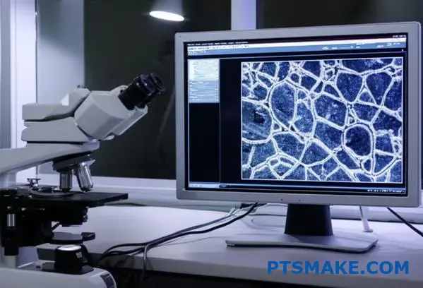
How do you interpret a micrograph of a sintered Metal Injection Molding (MIM) part?
A micrograph is not just a picture. It’s a detailed story about the part’s internal quality. Understanding it is key to predicting performance.
When I look at one, I’m not just seeing patterns. I’m assessing the success of the sintering process.
Key Microstructural Indicators
We focus on a few critical features. These tell us about the part’s future strength and reliability. The main ones are grain size, grain boundaries, and porosity.
Here’s a quick breakdown:
| Feature | What It Tells Us |
|---|---|
| Grain Size | Affects strength and hardness. |
| Grain Boundaries | The "glue" holding grains together. |
| Porosity | Voids that can weaken the part. |
Proper analysis ensures the final Metal Injection Molding component meets your exact specifications.
Decoding the Microstructure
Going deeper, the relationship between these features and mechanical properties becomes clear. It’s a direct cause-and-effect link that we’ve seen in past projects at PTSMAKE. This analysis is fundamental to our quality assurance.
Grain Size and Boundaries
We typically look for fine, uniform grains. A structure with consistent, equiaxed grains14` often indicates a well-controlled process and results in higher strength and hardness.
The grain boundaries should be clean and well-defined. If impurities are present at these boundaries, they can act as weak points, leading to premature failure under stress.
The Challenge of Porosity
Porosity is the enemy of performance. We distinguish between two types:
- Intra-granular: Pores trapped inside the grains.
- Inter-granular: Pores located at the grain boundaries.
Inter-granular porosity is more dangerous. It can link up, forming a network that drastically reduces the part’s ductility and toughness. We aim for a density above 97% to minimize this risk.
Linking Microstructure to Performance
This table summarizes the direct impact of microstructure on key properties:
| Microstructural Feature | Impact on Mechanical Property |
|---|---|
| Fine, Uniform Grains | Increases Strength & Hardness |
| High Porosity | Reduces Ductility & Strength |
| Contaminated Boundaries | Decreases Toughness |
| Well-Sintered Necks | Enhances Overall Integrity |
Analyzing these features is a non-negotiable step. It ensures the sintered MIM part has the required strength and ductility to perform reliably in its final application, preventing unexpected field failures.
How do you adapt a Metal Injection Molding (MIM) process for micro-scale components?
Adapting the Metal Injection Molding process for micro-scale parts introduces unique hurdles. It’s not just about shrinking everything down. We must start with ultra-fine metal powders.
These powders are much smaller than those used in conventional MIM. This is essential for accurately filling tiny mold cavities.
Specialized Equipment is Non-Negotiable
Success in Micro-MIM depends on specialized machinery and tooling. Molds require micro-features with extreme precision. Injection molding machines need superior control.
| Feature | Conventional MIM | Micro-MIM |
|---|---|---|
| Powder Size | 5-25 microns | < 5 microns |
| Tooling Tolerance | Standard | Extremely Tight |
| Injection Control | Precise | Ultra-Precise |
At the micro level, physics behaves differently. Forces that are negligible in standard MIM become dominant. This is a critical factor we always consider in projects at PTSMAKE.
The Influence of Micro-Scale Forces
Surface tension and static electricity have a much greater impact on ultra-fine powders. These forces cause particles to clump together. This makes consistent powder handling and mixing difficult.
This agglomeration directly affects the feedstock’s consistency. It can lead to an uneven distribution of powder within the binder system. The resulting rheological behavior15 can be unpredictable during injection.
This unpredictability can cause defects. Issues like incomplete filling of the mold cavity or variations in part density are common if not managed correctly. Precise process control is essential to overcome these challenges. We have learned through our testing that specialized feedstock formulation is key.
Overcoming Material Challenges
| Challenge | Impact on Micro-MIM | Solution |
|---|---|---|
| Surface Tension | Powder agglomeration | Optimized binder systems |
| Static Electricity | Inconsistent powder flow | Anti-static handling |
| Poor Feedstock Flow | Incomplete mold filling | High-precision injection units |
Micro-MIM demands a specialized approach. Success hinges on using ultra-fine powders, precision tooling, and advanced molding machines. Understanding and controlling forces like surface tension and static electricity is absolutely crucial for achieving the required part quality and consistency.
The challenges of Micro Metal Injection Molding don’t end once the part is molded. The debinding and sintering stages are equally critical and present their own set of difficulties for micro-scale components.
Debinding and Sintering Micro Parts
Micro parts have a significantly higher surface-area-to-volume ratio. This property drastically accelerates the debinding process. If not controlled carefully, it can lead to part distortion or cracking.
During sintering, this high ratio also means parts reach the required temperature much faster. Grain growth can become a major issue, potentially compromising the final mechanical properties of the tiny component. Precise thermal profiling is not just a recommendation; it’s a requirement.
A Comparative Look
In our work with clients, we’ve found that modifying the thermal cycles is key. Small adjustments can make a big difference in the final product’s integrity.
| Process Stage | Standard MIM Concern | Micro-MIM Concern |
|---|---|---|
| Debinding | Binder removal rate | Rapid, uncontrolled removal |
| Sintering | Shrinkage control | Excessive grain growth |
| Handling | Part durability | Fragility, part loss |
In conclusion, adapting the MIM process for micro-scale components is a complex task. It requires more than just scaling down equipment. It demands a deep understanding of material science and micro-scale physics.
From ultra-fine powders and precision tooling to managing forces like static electricity, every step must be meticulously controlled. Success lies in navigating these unique challenges with expertise. At PTSMAKE, we leverage our experience to master these intricacies, ensuring high-quality micro components from start to finish.
How can you leverage process simulation to improve Metal Injection Molding (MIM) outcomes?
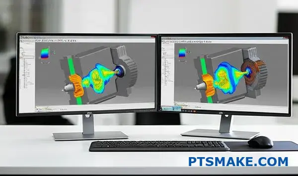
Process simulation software, like Moldflow, is a powerful tool in modern manufacturing. It moves beyond theory into practical application. It’s like having a crystal ball for the Metal Injection Molding process.
At PTSMAKE, we use it to visualize exactly how the feedstock will behave inside the mold. This helps us predict and solve problems before they happen. It’s a critical step in our quality assurance process.
| Aspect | Without Simulation | With Simulation |
|---|---|---|
| Defect Risk | High (Discovered late) | Low (Predicted early) |
| Mold Rework | Frequent | Minimal |
| Time-to-Market | Slower | Faster |
| Cost | Higher | Lower |
This predictive power is key to de-risking a project. It ensures the first physical parts we produce are much closer to perfection, saving valuable time and resources.
A Digital First Approach to MIM
We integrate simulation deep into our workflow. It’s not an afterthought; it’s a foundational step. This allows us to build a digital twin of the molding process, providing insights that are impossible to see with the naked eye. This digital-first approach is central to our commitment to precision.
Predicting Feedstock Flow
The first step is simulating the injection phase. The software shows us a detailed animation of how the feedstock fills the mold cavity. It considers factors like pressure, temperature, and material viscosity. This ensures the part fills completely and uniformly, which is crucial for complex geometries.
Identifying and Eliminating Defects
This flow analysis immediately highlights potential trouble spots.
| Defect Type | Simulation’s Role |
|---|---|
| Weld Lines | Predicts where melt fronts meet |
| Air Traps | Shows where air can be trapped |
| Sink Marks | Identifies areas of uneven cooling |
By seeing these issues on a screen, we can adjust the mold design or process parameters to eliminate them. This proactive troubleshooting is far more efficient than reactive fixes on physical parts.
Optimizing Gate and Runner Design
Where the material enters the part (the gate) is critically important. Simulation helps us test multiple gate locations virtually. We can find the optimal spot that ensures a balanced fill, minimizes stress in the part, and reduces the visibility of weld lines.
Simulating Sintering for Final Accuracy
A unique advantage for MIM is the ability to simulate sintering. The software predicts how the part will shrink and potentially distort during this final heating stage. It accounts for factors like volumetric shrinkage16 to forecast the final dimensions with remarkable accuracy. This ensures the final metal part meets tight tolerances.
Process simulation transforms Metal Injection Molding from an art into a data-driven science. It provides a digital blueprint for success, allowing us to refine the mold and process on a computer, ensuring a more predictable, cost-effective, and higher-quality outcome before manufacturing begins.
Unlock Precision MIM Solutions with PTSMAKE Expertise
Ready to elevate your project with advanced Metal Injection Molding? Contact PTSMAKE for a fast, no-obligation quote and discover why leading manufacturers trust us for complex, high-precision MIM parts. Take the next step—request your inquiry today!

Discover how material flow science is crucial for optimizing MIM process parameters and achieving superior part quality. ↩
Learn how material flow and particle alignment affect part accuracy during sintering. ↩
Understand how this specific steel structure provides excellent corrosion resistance and formability. ↩
Discover how this heating process transforms powder into a dense, strong metal part. ↩
Click to understand how this metric impacts the consistency and quality of your final parts. ↩
Learn how atomic movement solidifies metal parts during the crucial sintering phase. ↩
Learn more about this heat treatment process and how it selectively hardens the surface of a metal part. ↩
Discover how this principle affects the final dimensions and precision of your MIM parts. ↩
Learn about the thermal decomposition that removes binders before the final high-temperature sintering stage. ↩
Learn how this heat treatment process dramatically increases material strength for high-performance applications. ↩
Learn how temperature differences create internal forces that cause distortion. ↩
Explore how the sintering process affects your part’s final strength, dimensions, and overall performance. ↩
Understand how spreading initial costs over production units impacts your project’s total cost. ↩
Discover how grain shape influences a component’s strength and long-term durability. ↩
Learn how feedstock flow characteristics are crucial for producing high-quality, defect-free micro components. ↩
Understand how this crucial metric determines the final accuracy and structural integrity of your MIM components. ↩