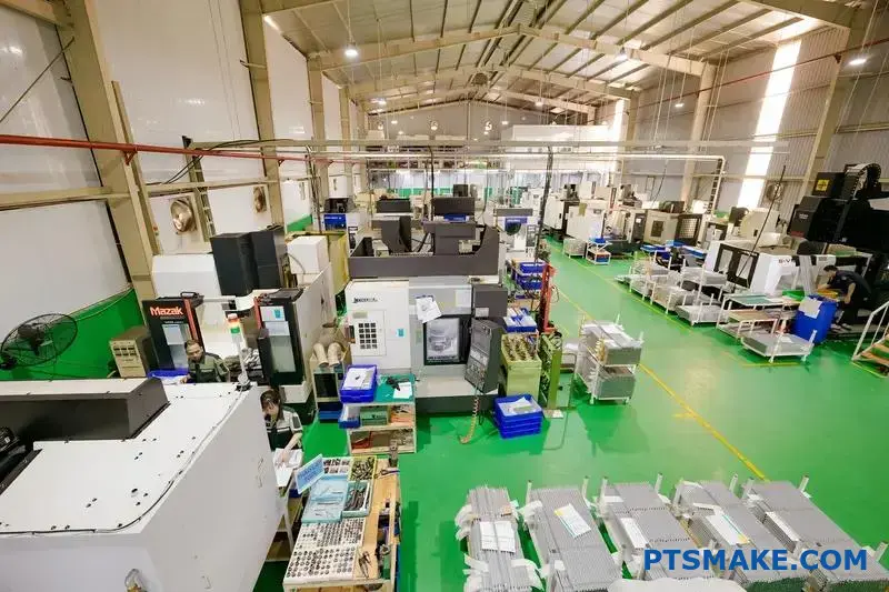
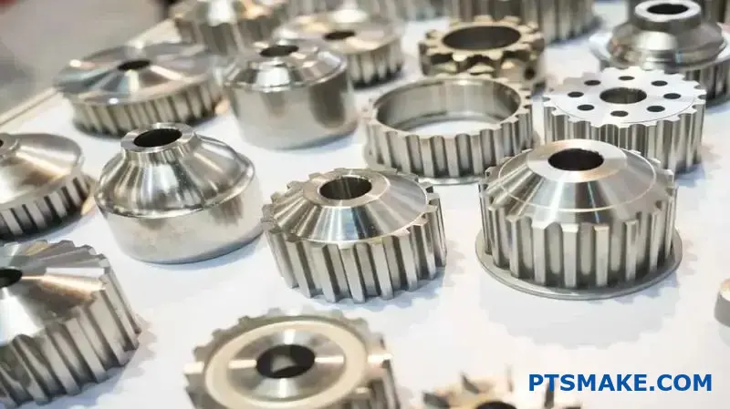
High pressure die casting sounds straightforward until you face real production challenges. You deal with complex defects, unpredictable cycle times, and quality issues that cost thousands in scrap and delays.
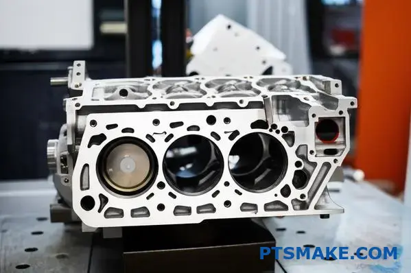
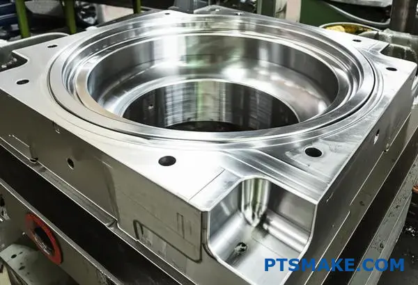
High pressure die casting is a metal forming process that injects molten metal into steel dies under extreme pressure (typically 1,500-30,000 psi), creating precise, near-net-shape parts with excellent surface finish and dimensional accuracy.
I’ve worked with manufacturers who struggle with these same issues daily. This guide covers the practical knowledge you need to troubleshoot problems, optimize processes, and make data-driven decisions that improve your production outcomes.
What is the core principle of high pressure die casting?
The core principle is right in the name: high pressure. This isn’t just about filling a mold. It’s about injecting molten metal with immense force and speed.
This fundamental action sets it apart from all other casting methods. It’s the difference between pouring and shooting.
The Power of Pressure
High pressure forces the metal into every tiny detail of the mold cavity. This ensures the final part matches the design with incredible precision, creating a "net shape" part.
Speed and Structure
The rapid injection also leads to quick cooling. This creates a fine-grained microstructure in the material, which significantly enhances its strength and durability.
| Feature | High Pressure Die Casting | Other Methods |
|---|---|---|
| Injection Speed | Extremely High | Low to Medium |
| Pressure | 10-200 MPa | Gravity / Low |
| Final Shape | Net Shape | Near Net Shape |
| Grain Structure | Fine & Dense | Coarser |
Unpacking the Process
The defining factor is the velocity at which the molten metal enters the die. We’re talking about speeds that can exceed 100 meters per second. This speed, combined with intense pressure, is crucial.
Think of it like this. Gravity casting is like gently pouring water into a glass. High pressure die casting is like using a fire hose to fill that same glass in a fraction of a second. The turbulence is controlled to ensure complete fill.
Why This Matters
This process minimizes defects. The high pressure squeezes the metal, drastically reducing porosity. Air has no time or space to get trapped. This results in a solid, dense, and reliable component.
In our work at PTSMAKE, we’ve seen how this directly impacts performance in critical applications. It’s not just about making a shape; it’s about engineering a superior material structure from the inside out. The rapid Solidification rate1 is key to achieving this.
Comparing Casting Pressures
| Casting Method | Typical Pressure Range | Primary Application |
|---|---|---|
| High Pressure | 10 – 200 MPa | Complex, thin-walled parts |
| Low Pressure | 0.02 – 0.1 MPa | Symmetrical parts (e.g., wheels) |
| Gravity Casting | Atmospheric | Simple, large parts |
This comparison shows why high pressure die casting is the go-to for complex and precise components.
The core principle of high pressure die casting is using extreme speed and force. This method injects molten metal to create strong, precise, net-shape parts with a fine grain structure. It is fundamentally different from slower, low-pressure casting methods.
What fundamentally defines a ‘good’ high pressure die casting?
A good high pressure die casting isn’t just about appearance. It’s fundamentally defined by a trio of key attributes. Achieving excellence in these areas is the true measure of quality.
The Pillars of a Quality Casting
Dimensional Accuracy
This means the part achieves its final "net shape" directly from the mold. It requires minimal to no secondary machining. This saves time and cost.
Mechanical Integrity
This is about what’s inside. A great casting has low porosity. This ensures the part is strong and reliable under stress.
Surface Finish
A smooth and consistent surface is crucial. It’s important for aesthetics and for parts that require sealing or coating.
These qualities don’t happen by chance. They are the direct result of mastering the core principles of the process.
| Attribute | Why It Matters |
|---|---|
| Dimensional Accuracy | Reduces post-processing costs and ensures proper assembly. |
| Mechanical Integrity | Guarantees part strength, durability, and safety in use. |
| Surface Finish | Improves appearance and functional performance. |
Achieving these attributes is a delicate balancing act. It all comes down to the precise control of pressure, temperature, and the velocity of the molten metal. Think of them as the three levers we pull to get the perfect result. If one is off, the entire part can be compromised.
The Control Triangle: Pressure, Temperature, and Velocity
Mastering Injection Velocity and Pressure
The speed at which we inject the metal is critical. Too slow, and the metal can solidify before filling the cavity, causing defects. Too fast, and we risk trapping air, which creates gas porosity. The final pressure phase compacts the metal, minimizing shrinkage.
The Role of Temperature
We must manage both the molten metal and mold temperatures. Correct temperatures ensure the alloy flows smoothly into every detail of the mold. Improper control can lead to stress, cracks, or brittle intermetallic compounds2 that weaken the final component. This is a common failure point.
In our projects at PTSMAKE, we often see how a small deviation in these parameters leads to significant quality issues. It’s a game of precision.
| Variable Imbalance | Potential Casting Defect |
|---|---|
| Excessive Injection Velocity | Gas Porosity, Flashing |
| Low Metal/Mold Temperature | Cold Shuts, Misruns |
| Insufficient Final Pressure | Shrinkage Porosity, Sinks |
In essence, a superior casting is defined by its accuracy, internal soundness, and surface quality. These outcomes are not accidental; they stem directly from the expert control of injection pressure, temperature, and velocity throughout the high pressure die casting process.
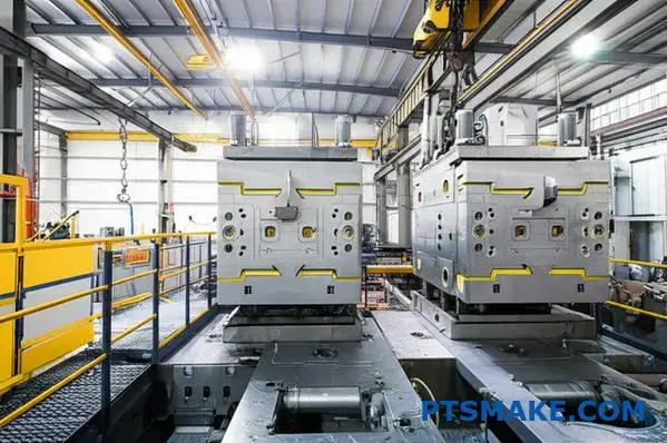
What are the main stages of a complete HPDC cycle?
The high pressure die casting process is a precise sequence. Each stage builds directly on the previous one. Skipping or rushing a step can compromise the entire batch.
Think of it as a well-choreographed dance. It begins with preparing the material and the mold.
The Initial Steps: Preparation is Key
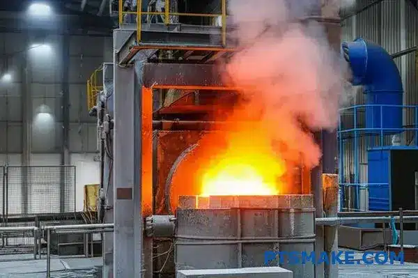
First, we melt the raw metal alloy. It’s heated until it reaches a specific molten state. Then, the liquid metal is transferred to the machine.
At the same time, the die mold is prepared. A lubricant is sprayed onto the mold surfaces. This helps control temperature and ensures the final part releases easily.
| Stage | Purpose |
|---|---|
| Melting & Transfer | Prepare the metal alloy for injection. |
| Die Preparation | Cool, lubricate, and clean the mold. |
The Core Cycle: From Liquid to Solid
Once the die is closed, the injection phase begins. The molten metal is forced into the die cavity under immense pressure. This happens in two stages: a slow shot to fill the "shot sleeve," followed by a high-speed plunger. This speed is critical for creating detailed, thin-walled parts.
The metal then cools and solidifies within the die. Controlling this cooling process is essential. Poor temperature management can introduce internal defects like porosity3, which weakens the final component. At PTSMAKE, we focus heavily on thermal management to ensure part integrity.
After solidification, the die opens and ejector pins push the casting out. The part may then be quenched in a liquid bath. This rapid cooling locks in the desired mechanical properties.
Finishing the Part
The final stage is trimming. Excess material, such as the runners, gates, and any flash, is removed from the casting. This can be done using a trim die or other mechanical methods. Now, the part is complete.
| Stage | Purpose |
|---|---|
| Injection | Fill the die cavity with molten metal. |
| Cooling | Allow the metal to solidify into the part shape. |
| Ejection | Remove the solidified casting from the mold. |
| Quenching | Rapidly cool the part to enhance properties. |
| Trimming | Remove excess material from the final part. |
From melting raw metal to trimming the final part, each stage in the HPDC cycle is vital. Precise control throughout this sequence ensures the final component meets all specifications for strength, finish, and dimensional accuracy.
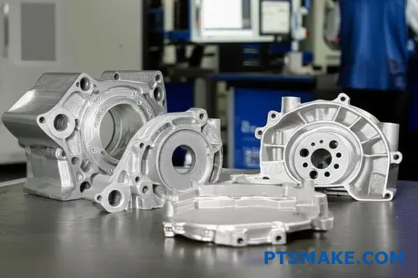
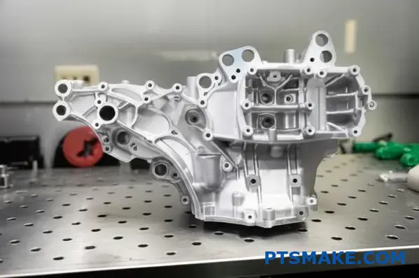
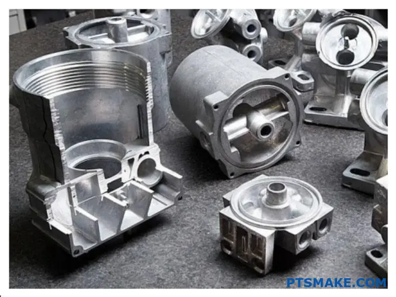
What are the common families of die casting alloys?
In high pressure die casting, alloy choice is critical. It defines the part’s final properties. The three main families are Aluminum, Zinc, and Magnesium. Each offers a unique blend of characteristics.
This makes them suitable for different applications. At PTSMAKE, we guide clients to the best fit. Let’s look at their core traits.
| Alloy Family | Key Feature | Common Use |
|---|---|---|
| Aluminum | Lightweight & Strong | Automotive Parts |
| Zinc | High Ductility & Finish | Hardware, Electronics |
| Magnesium | Ultra-Lightweight | Aerospace, Portables |
This table provides a quick overview. We can now explore them in more detail to understand their practical applications.
Aluminum Alloys
Aluminum is the workhorse of die casting. It offers an excellent combination of strength and low weight. Its corrosion resistance is also quite good for many environments, making it versatile.
Key Properties
The most common is A380. Its casting temperature is around 660°C. This high temperature affects tool life. Understanding the alloy’s eutectic point4 is crucial for controlling solidification and final grain structure for optimal part performance.
Zinc Alloys
Zinc alloys, like ZAMAK 3, are known for their fluidity. This allows for thin walls and intricate details. They cast at lower temperatures, around 420°C, which is a significant advantage.
Strengths and Weaknesses
This lower temperature means longer die life, a cost benefit we often discuss with clients at PTSMAKE. Zinc has excellent strength but is heavier than aluminum. Its corrosion resistance is moderate without secondary finishing.
Magnesium Alloys
Magnesium is the lightest structural metal available for die casting. Its strength-to-weight ratio is outstanding. It is perfect for applications where every gram counts, like in aerospace or high-end electronics.
Casting Considerations
Its casting temperature is similar to aluminum. However, magnesium requires special handling due to its reactivity. Proper safety protocols for high pressure die casting of magnesium are non-negotiable in our facilities.
| Characteristic | Aluminum (A380) | Zinc (ZAMAK 3) | Magnesium (AZ91D) |
|---|---|---|---|
| Casting Temp (°C) | ~660 | ~420 | ~650 |
| Strength-to-Weight | Excellent | Good | Superior |
| Corrosion Resistance | Good | Moderate | Fair (needs coating) |
Choosing the right alloy is a trade-off. Aluminum offers balance, zinc provides detail and finish, while magnesium delivers ultimate lightweight performance. Your project’s specific needs for strength, weight, and environment will determine the ideal material choice.
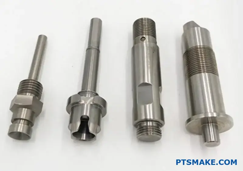
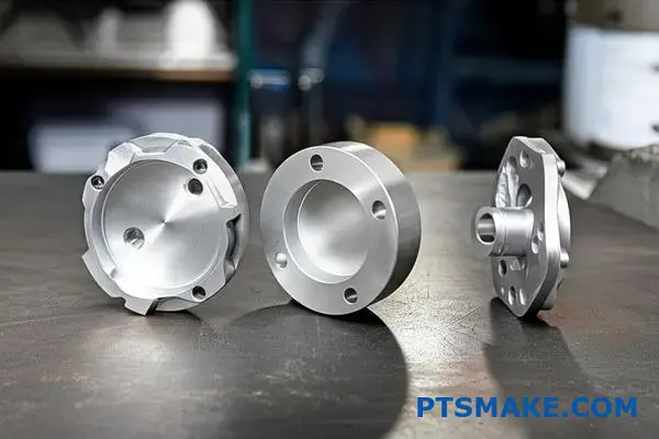
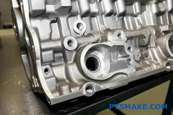
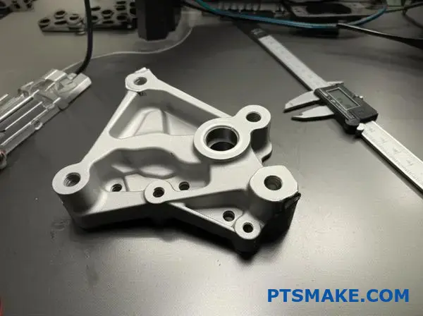
What are the typical post-casting operations and their purposes?
A raw casting is rarely the final product. Post-casting operations are essential steps. They refine the part, making it ready for its final application.
These processes ensure the part meets design specifications. They range from simple cleaning to high-precision machining.
Common Downstream Processes
Each operation has a specific, crucial purpose. They work together to create the final component.
| Operation | Primary Purpose |
|---|---|
| Trimming | Remove unwanted excess material |
| Shot Blasting | Surface cleaning and preparation |
| Machining | Achieve critical, tight tolerances |
| Finishing | Add protection and improve aesthetics |
Why Each Step is Non-Negotiable
Post-casting processes aren’t optional extras. They are integral to manufacturing a reliable part. Skipping a step can compromise the part’s integrity and function.
From Rough to Ready: Trimming and Blasting
Trimming is the first step. It removes excess material like flash, runners, and gates left from the casting process. This is crucial for proper fit and safety.
Shot blasting follows. It uses abrasive media to clean the part’s surface. This removes any scale or oxides. It also creates a uniform texture, which is an ideal base for painting or coating.
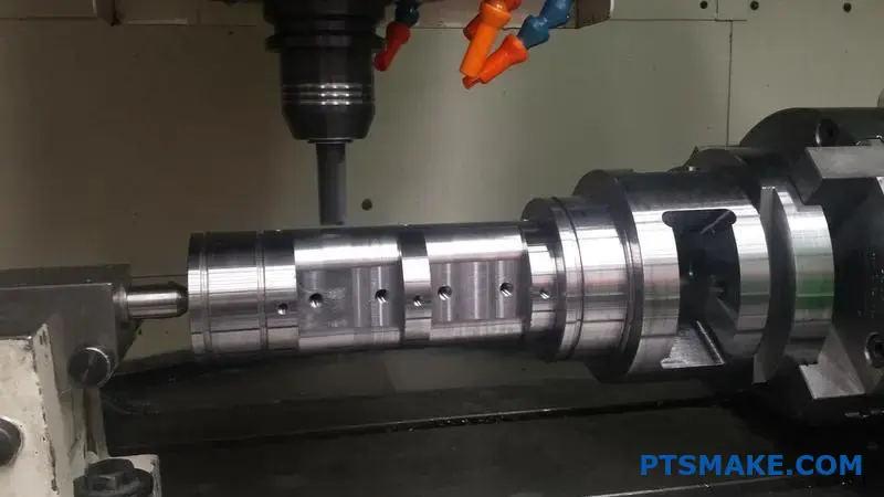
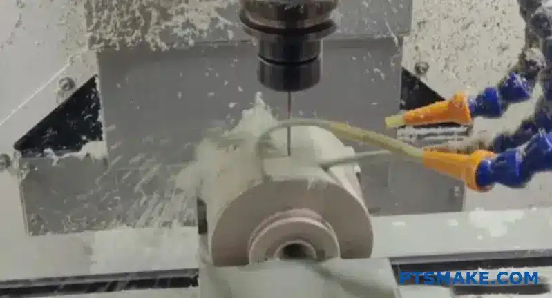
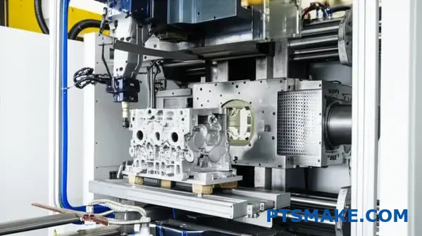
The Precision Step: CNC Machining
This is where we at PTSMAKE often add significant value. While a process like high pressure die casting is very precise, machining is needed for features with the tightest tolerances.
This includes threaded holes, mating surfaces, and O-ring grooves. Machining ensures these critical features are perfectly dimensioned. It can sometimes reveal sub-surface porosity5, which is vital to identify for high-performance parts.
The Final Touch: Finishing Operations
Finishing is the final stage. It protects the part and provides the desired appearance. The choice depends on the application environment and aesthetic requirements.
| Finishing Type | Key Benefit | Typical Application |
|---|---|---|
| Powder Coating | High durability, color choice | Automotive parts, enclosures |
| Painting | Versatile aesthetics, low cost | Consumer electronics |
| Anodizing | Corrosion & wear resistance | Aerospace, medical devices |
Post-casting operations transform a rough casting into a finished, functional component. These essential steps, from trimming and blasting to precision machining and final coating, ensure the part meets every specification for performance, fit, and appearance.
How do you systematically troubleshoot porosity in a casting?
When porosity appears, don’t guess. A systematic approach is crucial. The first step is always identification. Is it gas or shrinkage porosity? This initial diagnosis dictates your entire troubleshooting path, saving you time and resources.
This simple distinction helps you focus. You can immediately narrow down the potential causes. It prevents you from adjusting the wrong parameters.
A logical flowchart begins with this question.
| Porosity Type | Key Question | Next Step |
|---|---|---|
| Gas | Are the pores smooth and spherical? | Investigate Gas Sources |
| Shrinkage | Are the pores jagged and angular? | Analyze Solidification & Feeding |
Once you identify the type, you can follow a logical path to the root cause. This structured method is essential, especially in complex processes like high pressure die casting. Let’s break down the two main branches of our troubleshooting flowchart.
Troubleshooting Gas Porosity
Gas porosity comes from trapped air or gas released from the molten metal. The key is to find where the gas is coming from and why it’s not escaping. Your investigation should focus on flow and venting.
| Potential Cause | Corrective Action |
|---|---|
| Inadequate Venting | Add or enlarge vents; ensure vents are clean. |
| High Turbulence | Adjust gate velocity to promote laminar flow. |
| Excessive Lubricant | Optimize spray cycle and amount; use a high-quality die release agent. |
| Moisture in Metal/Ladle | Ensure charge material is dry and preheat ladles properly. |
Troubleshooting Shrinkage Porosity
Shrinkage porosity is a volume deficit. It happens when liquid metal can’t feed a section that is solidifying. This often occurs in thicker sections or areas isolated from the gate. Proper pressure and thermal management are vital. This prevents proper feeding as the metal solidifies, often leading to dendritic6 voids.
| Potential Cause | Corrective Action |
|---|---|
| Low Intensification Pressure | Increase final stage pressure to feed the casting. |
| Inadequate Gating/Feeding | Redesign runner and gate to feed thick sections last. |
| Part Geometry (Hot Spots) | Modify the part design to achieve uniform wall thickness. |
| Improper Cooling | Add cooling lines near hot spots or adjust cycle time. |
This flowchart simplifies troubleshooting. By first identifying the porosity type, you can systematically address potential causes. This targeted approach saves time and reduces scrap, leading to consistent, high-quality parts every time.
How would you reduce cycle time without sacrificing part quality?
A balanced approach is crucial here. Reducing cycle time isn’t about a single magic bullet. It requires analyzing the entire process.
We must look at every step carefully. The goal is improvement without compromise.
A Multi-Faceted Optimization Strategy
We focus on several key areas. These include die spray time and cooling efficiency. We also optimize robot automation paths.
Key Areas for Improvement
Each area offers significant time savings. But we always ensure quality remains the top priority. At PTSMAKE, this is our core principle.
| Process Stage | Potential Time Savings |
|---|---|
| Die Spray Optimization | 1-3 seconds |
| Enhanced Die Cooling | 2-5 seconds |
| Robotic Path Tuning | 1-2 seconds |
Analyzing the Critical Trade-Offs
Every adjustment involves a trade-off. For instance, reducing die spray saves time. However, it can also accelerate die wear. This leads to higher long-term costs. We must find the optimal balance.
Improving Die Cooling Efficiency
Faster cooling is a primary goal. It directly shortens the solidification time. This is especially critical in high pressure die casting. We need the material to reach thermodynamic equilibrium7 quickly but uniformly.
In our work, we often suggest conformal cooling channels. They follow the part’s contour. This ensures faster, more even heat extraction. It prevents part defects like warping.
Fine-Tuning Robot Automation
Robot paths are frequently overlooked. A standard path might have jerky motions. We analyze and smooth out these paths.
Shaving milliseconds from each movement adds up significantly over a production run. A direct, fluid path is always faster.
| Technique | Traditional Method | Optimized Approach |
|---|---|---|
| Die Cooling | Straight-drilled cooling lines | Conformal cooling channels |
| Robot Path | Point-to-point linear moves | Smoothed, continuous arc paths |
| Die Spray | Fixed duration spray | Variable, targeted application |
A successful strategy integrates optimized die spray, advanced cooling, and refined automation. This holistic view reduces cycle time while upholding part quality and protecting tool life, creating a more efficient and reliable manufacturing process from start to finish.
Analyze a case of a recurring blister defect on a casting.
A client recently faced a persistent issue. Blisters appeared on their casting’s surface after painting. This is a classic manufacturing puzzle.
The challenge is pinpointing the exact cause. Was it trapped gas from the casting process? Or maybe excess lubricant? It could even be hidden moisture.
We developed a clear plan to investigate. This approach helps avoid guesswork. It systematically eliminates possibilities to find the true root cause.
A Step-by-Step Investigation Plan
Our first step is always a thorough visual check. We examine the blisters’ size, shape, and location on the part. This gives us initial clues.
Next, we dive into the process data. A small change in parameters can have a big impact. This is especially true in a process like high pressure die casting.
Process Parameter Review
We check everything from injection speed to die temperature. We compare the settings for good batches versus bad ones. The data often tells a story.
Distinguishing Potential Causes
To narrow it down, we look for specific signs. Each cause leaves a different fingerprint. For instance, hidden porosity8 is a common source of gas-related blisters that appear after heating or painting.
Here is a simple breakdown we use at PTSMAKE:
| Defect Source | Typical Blister Appearance | Location |
|---|---|---|
| Trapped Gas | Smooth, round, often shiny inside | Thicker sections or last to fill |
| Lubricant Issue | Irregular shape, may have residue | Near ejector pins, complex areas |
| Moisture | Varies, can be small and numerous | Can be anywhere on the surface |
Finally, we might section a defective part. Looking at it under a microscope provides definitive proof. This confirms if gas pockets are present just below the surface.
This systematic plan is key. It moves beyond assumptions. By carefully inspecting, analyzing data, and comparing evidence, we can confidently identify the root cause of blistering. This ensures the right fix is applied, preventing future recurrence.
How would you conduct a cost-down analysis of a casting job?
Real cost reduction is not about squeezing supplier margins. It’s about engineering a more efficient process. Smart business principles must guide technical decisions.
In high pressure die casting, we focus on four main cost drivers. These are the areas where small technical changes can make a big financial impact.
Improving these drivers leads to sustainable savings. It’s a win-win for both the client and the manufacturer.
Let’s look at the core areas for analysis.
| Cost Driver | Primary Impact |
|---|---|
| Metal Yield | Material Waste |
| Cycle Time | Machine & Labor Efficiency |
| Die Life | Tooling Amortization |
| Energy Consumption | Overhead Costs |
Optimizing these is key to a successful cost-down strategy.
To truly cut costs, you have to dig into the technical details. It’s about making the process itself cheaper to run, not just buying cheaper materials. At PTSMAKE, we partner with clients to analyze these areas.
Optimizing Metal Yield
A major cost is the raw material that doesn’t end up in the final part. We focus heavily on runner and gating design. Using flow simulation software, we can often reduce the material in the runner system by 10-15%, which is a direct saving.
Reducing Cycle Time
Faster cycles mean higher output and lower costs per part. We analyze die cooling channels to ensure rapid, even cooling. We also optimize robot extraction paths and die spray applications. Each second saved adds up significantly over a production run.
Extending Die Life
Tooling is a huge investment. The longer a die lasts, the lower the amortized cost per part. A primary cause of die failure is thermal fatigue9. Proper thermal management, along with advanced coatings and the right tool steel, can dramatically extend a die’s operational life.
Our analysis often shows that a slightly more expensive die coating can double the tool’s lifespan.
| Driver | Technical Improvement |
|---|---|
| Metal Yield | Redesign runner & gates; optimize overflow |
| Cycle Time | Enhance cooling circuits; automate extraction |
| Die Life | Apply advanced coatings; improve heat treatment |
| Energy | Upgrade furnace insulation; optimize machine idle states |
Lowering Energy Consumption
Energy is a direct overhead. We look at everything from furnace efficiency to the power usage of the casting machine itself. Modern, well-maintained equipment simply uses less power per part produced.
True cost-down analysis in casting is an engineering exercise. By focusing on technical drivers like metal yield, cycle time, die life, and energy use, we unlock real, sustainable savings that go far beyond simple price negotiations.
Develop a comprehensive strategy to maximize die life.
Creating a long-term plan is not just about maintenance. It starts much earlier. A comprehensive strategy integrates every stage of the die’s lifecycle.
Initial Die Design
Proper design is your first line of defense. Generous radii and smooth transitions prevent stress concentrations from the start.
Treatment and Preparation
Heat treatment and pre-heating are critical. They prepare the die steel for the intense conditions of production.
A successful strategy balances these key areas:
| Strategy Pillar | Key Action | Primary Goal |
|---|---|---|
| Design | Use generous radii | Reduce stress points |
| Heat Treatment | Follow precise protocols | Achieve optimal hardness |
| Pre-Heating | Control temperature rise | Minimize thermal shock |
| Maintenance | Schedule regular checks | Prevent catastrophic failure |
A Holistic Lifecycle Approach
A truly effective strategy connects every phase. Focusing only on reactive maintenance is a common mistake. The foundation for a long die life is set during the design phase. At PTSMAKE, we emphasize this from day one.
Integrating Design with Process
Design choices directly impact how the die handles stress. For instance, a well-designed cooling channel system helps manage thermal loads. This reduces the risk of intergranular stress10 build-up over thousands of cycles. Optimizing these parameters is crucial in high pressure die casting.
Proactive vs. Reactive Maintenance
A planned maintenance schedule is always better than waiting for a breakdown. It prevents unscheduled downtime and more costly repairs. In our projects, we’ve seen proactive plans extend die life significantly.
This comparison illustrates the difference:
| Aspect | Proactive Maintenance | Reactive Maintenance |
|---|---|---|
| Timing | Scheduled intervals | After failure occurs |
| Cost | Lower, predictable | High, unpredictable |
| Downtime | Planned, minimal | Unplanned, extensive |
| Die Life | Maximized | Significantly reduced |
A welding schedule should also be part of this proactive plan. Regular, minor repairs are far more effective than major overhauls. This approach keeps the die in optimal condition.
A comprehensive strategy links initial design, precise treatments, optimized processes, and regular maintenance. This integrated plan is essential for maximizing the operational life and value of your die.
How do you bridge the gap between simulation and reality?
Simulations provide a powerful starting point. But they are not the final word. The real magic happens when we connect the digital model to the physical factory floor. It’s a two-way street.
Starting with Simulation
We use flow and thermal simulations to guide our initial setup. This gives us a strong, data-driven baseline. It helps predict potential issues before they happen. This saves time and material costs.
Initial Process Parameters
| Parameter | Simulation Guideline | Initial Machine Setting |
|---|---|---|
| Melt Temperature | 680°C | 685°C |
| Mold Temperature | 220°C | 225°C |
| Injection Speed | 2.5 m/s | 2.4 m/s |
| Pressure | 100 MPa | 105 MPa |
This table shows how closely our initial settings follow the simulation’s recommendations.
Creating the Feedback Loop
The initial setup is just the beginning. The crucial next step is refining the simulation. We use real-world data from the first production runs to improve the model. This iterative process turns a good simulation into a great one.
We collect data from every shot. This includes temperatures, pressures, and cycle times. We also perform detailed quality checks on the finished parts. This feedback is essential for accurate adjustments.
This approach is especially important for complex jobs. For example, in high pressure die casting, minor process variations can have large effects. A well-tuned simulation helps us manage these complexities effectively. Our goal is continuous improvement through this feedback loop.
Calibrating with Real-World Data
The process of updating the simulation with production data is key. This model calibration11 makes our future predictions incredibly accurate. It ensures the digital twin truly reflects the physical process.
| Data Type | Collection Method | Simulation Adjustment |
|---|---|---|
| Fill Pattern | Short shot analysis | Modify gate locations or flow rates |
| Part Warpage | CMM inspection | Adjust cooling channel temperatures |
| Porosity | X-ray inspection | Refine injection pressure profile |
Based on our tests, this closed-loop process reduces setup times for similar parts by up to 30%. It builds a library of knowledge that benefits every future project here at PTSMAKE.
The true value of simulation is realized when it’s part of a feedback loop. We use it to guide our initial setup, then refine it with real-world production data. This method ensures continuous improvement and predictability.
Diagnose a quality issue with multiple potential root causes.
Dealing with intermittent flash and dimensional instability is one of the toughest challenges. The problem appears, then vanishes. This makes quick fixes nearly impossible.
Guesswork wastes time and money. A systematic approach is essential. We use a diagnostic tree, like an Ishikawa (or Fishbone) diagram, to map out every possibility. This method turns a complex, ambiguous problem into a structured investigation, ensuring no stone is left unturned.
| Problem Area | Key Question |
|---|---|
| Machine | Is the equipment consistent? |
| Die (Tool) | Is the mold integrity compromised? |
| Process | Are operating parameters stable? |
| Material | Is the raw material consistent? |
A Fishbone diagram helps us visualize potential causes. We categorize them to tackle the issue methodically. This clarity is crucial when multiple factors could be the culprit. At PTSMAKE, we start by mapping the primary "bones" of the diagram.
The Machine Factor
First, we look at the equipment itself. Inconsistent machine performance is a common source of intermittent problems.
Clamping Force Instability
Is the clamp force fluctuating during a run? A drop in pressure, even for a moment, can allow flash to form. We check hydraulic pressures and mechanical toggles for any variation.
Platen Parallelism
If the platens are not perfectly parallel, the clamping force will be uneven across the die face. This can also lead to flash and dimensional issues.
The Die (Tooling) Factor
Next, we inspect the die. Even the most robust tools experience wear over time, which can introduce subtle defects.
| Die Component | Potential Issue | Consequence |
|---|---|---|
| Parting Line | Wear or damage | Flash |
| Vents | Clogged or undersized | Trapped gas, short shots |
| Core Pins/Slides | Misalignment | Dimensional instability |
The Process Factor
Process parameters are the most dynamic variables. A slight deviation can have a significant impact, especially in sensitive processes like high pressure die casting. We analyze shot-to-shot data to find inconsistencies. It’s about maintaining a stable Process Window12. Temperature, pressure, and speed must be tightly controlled.
A structured diagnostic tree turns ambiguity into an actionable plan. This method systematically eliminates variables, guiding your team to the true root cause. It prevents guesswork and ensures a permanent solution is found efficiently.
Design a project to improve Overall Equipment Effectiveness (OEE).
Improving OEE can seem like a huge task. The key is to start small. Let’s apply lean manufacturing to one area.
We will design a project focused on Availability. A great starting point is reducing equipment setup times.
Choosing a Pilot Project
For our example, we’ll focus on a common challenge in manufacturing. The goal is to minimize downtime between production runs.
Focus: Die Changeover Time
Reducing die changeover time is a perfect small-scale project. It directly boosts machine Availability, a core OEE component. Success here provides a clear win.
| OEE Component | Project Focus | Expected Outcome |
|---|---|---|
| Availability | Reduce Die Changeover Time | More production uptime |
| Performance | – | (Not targeted in this project) |
| Quality | – | (Not targeted in this project) |
Applying Lean Principles to HPDC
To tackle die changeover, we use a lean tool called SMED. It stands for Single-Minute Exchange of Die. The goal isn’t literally one minute. It’s about making changeovers fast and efficient.
In past projects at PTSMAKE, we’ve found that a structured approach works best. This is especially true for complex processes like high pressure die casting.
A Step-by-Step Project Plan
A clear plan is essential for success. We break the project into manageable steps. This ensures the team stays focused and can measure progress accurately.
1. Observation and Data Collection
First, we videotape the current changeover process. The team watches it together. We document every single step and its duration. This creates a baseline to improve upon.
2. Identify and Separate Tasks
Next, we classify each step. Tasks are either "internal" (machine must be stopped) or "external" (can be done while running).
| Task Type | Definition | Example |
|---|---|---|
| Internal | Must be done when machine is off | Unbolting the old die |
| External | Can be done while machine is on | Preparing the next die |
3. Convert and Streamline
The main goal is to convert internal steps to external ones. We also look to simplify or eliminate steps. For example, we can implement [Poka-yoke](https://en.wikipedia.org/wiki/Poka-yoke)[^13] measures to prevent errors during setup, making it faster and safer. Streamlining the remaining internal tasks is the final piece.
Applying lean principles like SMED allows us to launch a focused project. By targeting die changeover time in high pressure die casting, we can achieve measurable gains in machine Availability. This small win builds momentum for larger OEE improvements across the facility.
Accelerate Your High Pressure Die Casting Success with PTSMAKE
Ready to optimize your next high pressure die casting project? Connect with PTSMAKE for expert advice, rapid quotes, and world-class precision manufacturing solutions—delivered on time, to your exact specifications. Reach out now for your custom quote and take your production to the next level!

Discover how this rapid cooling process defines the part’s final strength and surface finish. ↩
Understand how these microscopic structures can impact the overall strength and durability of your die-cast parts. ↩
Understand how this common defect forms and how we prevent it to maximize part durability. ↩
Click to understand how this melting behavior impacts the final part’s mechanical properties and quality. ↩
Learn how this internal defect impacts part integrity and what inspection methods can uncover it. ↩
Discover how these crystal structures form and why they are critical to understanding shrinkage in metal casting. ↩
Understand the physics of how materials cool and solidify efficiently. ↩
Learn how internal voids form and affect the quality of your final casting surface. ↩
Discover how this material stress directly impacts your tooling budget and production uptime. ↩
Understand how this microscopic stress causes cracks and leads to die failure. ↩
Learn how calibrating models improves predictive accuracy and reduces costly physical trial runs. ↩
Explore how this parameter range is crucial for achieving consistent, high-quality production runs. ↩