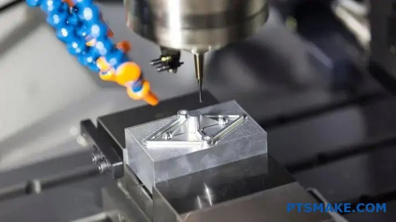
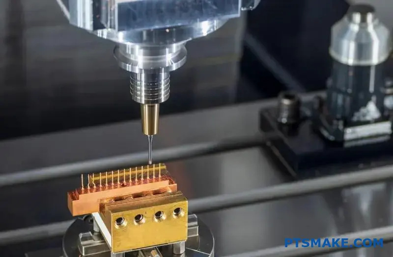
Finding the right metal forming process can make or break your project timeline and budget. Many engineers struggle with choosing between Metal Injection Molding (MIM) and die casting, often leading to costly redesigns, production delays, and compromised part performance.
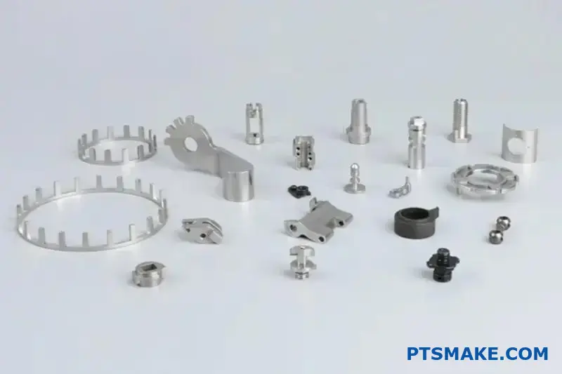
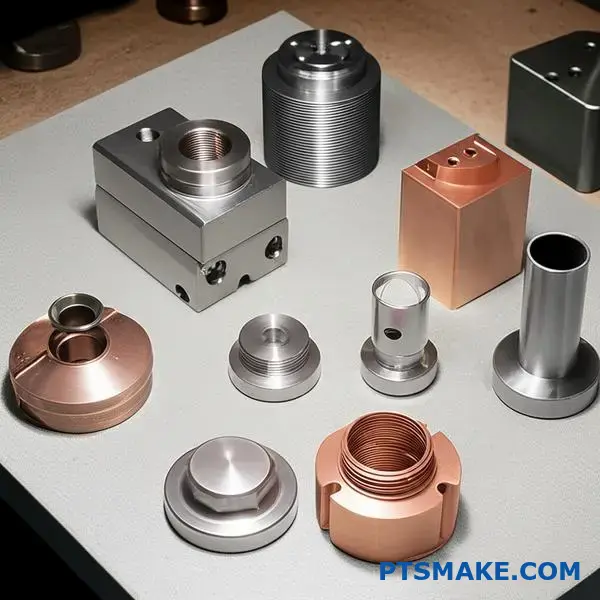
Metal Injection Molding (MIM) excels at producing small, complex, high-precision parts from high-melting-point materials like stainless steel, while die casting is optimal for larger, structural components from aluminum, zinc, or magnesium alloys with faster cycle times.

The decision between these processes involves 20 critical factors that most engineers overlook. I’ll walk you through each consideration with real data, case studies, and practical decision frameworks that will save you months of trial and error.
How does feedstock preparation differ for Metal Injection Molding (MIM) and Die Casting?
The journey from raw material to a finished part starts very differently for MIM and Die Casting. This initial stage is crucial. It directly impacts the final product’s quality and cost.
Understanding this difference is key when comparing metal injection molding vs die casting.
MIM’s Complex Feedstock Creation
MIM feedstock preparation is a multi-step, scientific process. It involves blending fine metal powders with a polymer binder. This mixture is then heated and mixed to create a consistent, dough-like substance. Finally, it’s pelletized for the molding machine.
Die Casting’s Simpler Method
Die casting, in contrast, is more straightforward. It begins with solid metal ingots or bars. These are simply melted down in a furnace. The molten metal becomes the "feedstock," ready to be injected into the die.
A quick comparison highlights the core differences.
| Feature | Metal Injection Molding (MIM) | Die Casting |
|---|---|---|
| Starting Material | Fine Metal Powder & Binder | Metal Ingots |
| Process Steps | Blending, Mixing, Pelletizing | Melting |
| Complexity | High | Low |
The detailed preparation of MIM feedstock is where we gain immense control over the final part’s characteristics. This is a critical distinction in the metal injection molding vs die casting debate. At PTSMAKE, we see this stage as foundational to achieving superior results.
Deep Dive into Quality and Flexibility
The meticulous MIM process allows for precise control. We can create custom alloys by blending different metal powders. This ensures the final material has the exact properties required, from hardness to corrosion resistance.
The binder is also critical. Its formulation ensures the metal powder flows smoothly into the mold. This precise mixing is crucial for achieving the desired rheological properties1 of the feedstock, which prevents defects like voids or cracks in the final part. It’s a level of control die casting cannot match.
Cost and Material Trade-offs
Die casting’s simplicity means lower initial material costs and faster preparation. However, you are often limited to standard, lower-melting-point alloys like aluminum and zinc.
MIM’s complex feedstock preparation carries a higher upfront cost. But it opens the door to a vast range of materials, including stainless steels, titanium, and superalloys, enabling the production of parts with far superior mechanical properties.
| Aspect | Metal Injection Molding (MIM) | Die Casting |
|---|---|---|
| Quality Control | Very High (custom alloys, binder control) | Moderate (depends on ingot quality) |
| Material Flexibility | Extremely High (steels, titanium, etc.) | Limited (mostly Al, Zn, Mg) |
| Initial Cost | Higher | Lower |
MIM’s intricate feedstock preparation, though more costly upfront, offers unparalleled control over material properties and design flexibility. Die casting provides a faster, more direct path from raw material to molten metal, but with significant material limitations.
What limits the wall thickness in each process fundamentally for Metal Injection Molding (MIM) and Die Casting?
Choosing the right process often comes down to wall thickness. It’s a critical design factor. MIM excels with thin, intricate walls.
It allows for complex geometries that are otherwise difficult to produce. But it has its limits.
Die casting, on the other hand, is better for larger, thicker parts. Yet, it also faces challenges when sections become too thick. Understanding these fundamental limits is key.
MIM: The Binder is the Bottleneck
In MIM, the main issue is removing the binder from the "green" part. This stage is called debinding.
For thick sections, this process becomes very slow and difficult. The binder can get trapped inside.
Die Casting: A Matter of Cooling
With die casting, the challenge is thermal. Molten metal must cool uniformly.
Thick sections cool much slower than thin ones. This uneven cooling can cause defects like porosity and internal stress.
Here’s a quick comparison.
| Process | Ideal Wall Thickness | Limiting Factor |
|---|---|---|
| MIM | 0.5 mm – 6 mm | Binder Removal |
| Die Casting | 1.5 mm – 15 mm | Cooling Rate |
When we analyze the metal injection molding vs die casting debate, the physics behind each process dictates the wall thickness limitations. It’s not just about what a machine can do, but about material science.
The Science Behind MIM’s Thickness Limit
In Metal Injection Molding, the raw material is a feedstock. It’s a mix of fine metal powder and a polymer binder. This binder must be removed completely before the part is sintered into a solid metal piece.
This removal, or debinding2, happens through thermal or chemical means. In sections thicker than 6-10 mm, the binder in the core has a long path to escape. If heated too quickly, the trapped binder can vaporize, creating internal cracks or blisters.
Based on our tests, we found that extending the debinding cycle for thick parts significantly increases processing time and cost. It often makes the process economically unviable.
Sintering Challenges in Thick MIM Parts
After debinding, the part is heated to just below its melting point. This is sintering. The metal particles fuse, and the part shrinks to its final density.
In a thick part, this shrinkage can be uneven. The exterior may densify faster than the interior. This differential shrinkage creates internal stress, which can lead to warping or cracking.
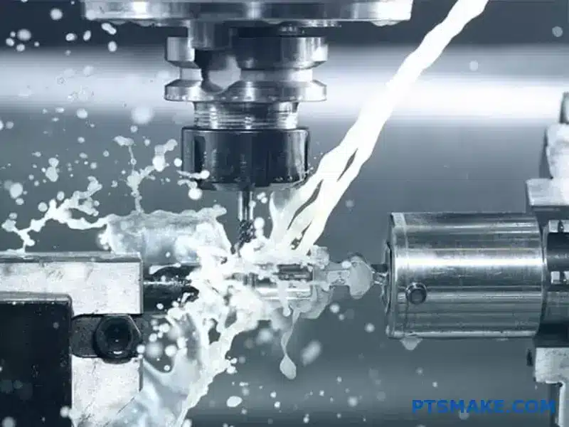
Die Casting’s Cooling Conundrum
Die casting involves injecting molten metal into a mold under high pressure. The process is extremely fast. The main challenge is extracting heat from the part efficiently and uniformly.
A thick section acts like a heat reservoir. While the outer surface touching the cool mold solidifies quickly, the core remains molten. This slow cooling in the center often leads to shrinkage porosity, a common defect. The part is simply not as strong as it should be.
| Defect Source | MIM | Die Casting |
|---|---|---|
| Primary Cause | Trapped Binder | Uneven Cooling |
| Key Defect | Cracks, Blisters | Porosity, Warping |
| Affected Stage | Debinding/Sintering | Solidification |
MIM’s wall thickness is limited by the chemical and physical process of binder removal and sintering. In contrast, die casting’s limitations are primarily thermal, related to managing heat during solidification. Both processes require careful design to avoid these fundamental issues.
What are the core mechanical properties derived from each process between Metal Injection Molding (MIM) and Die Casting?
The real story of a part’s strength is told by its internal structure. This microstructure is critical. It determines how a component will perform under real-world stress.
MIM: A Uniform Foundation
Metal Injection Molding (MIM) excels here. The sintering process creates a fine-grained, uniform microstructure. This consistency runs through the entire part. It leads to predictable and reliable mechanical properties.
Die Casting: A Tale of Two Layers
Die-cast parts are different. They often have a fine-grained "skin" on the outside. But the inside core is coarser. This structural divide can create performance inconsistencies.
| Feature | Metal Injection Molding (MIM) | Die Casting |
|---|---|---|
| Microstructure | Highly Uniform | Non-Uniform (Skin/Core) |
| Grain Size | Fine & Consistent | Fine (Skin), Coarse (Core) |
MIM’s Wrought-Like Isotropic Properties
The sintering stage is where MIM parts gain their superior properties. This process fuses the metal powder into a dense, solid mass. It creates a structure much like wrought metal.
The key benefit here is isotropic properties. This means the component has uniform mechanical strength. The strength is the same no matter which direction force is applied. This is a huge advantage for complex, high-stress applications.
Die Casting’s Anisotropic Challenge
In die casting, the molten metal cools very fast against the cold mold walls. This creates that fine-grained outer skin. The core, insulated by this skin, cools much more slowly. This results in a coarser grain structure internally.
This dual structure leads to anisotropic3 properties. The part’s strength varies depending on the direction. It’s typically stronger along the surface than through the core. This can limit its use in certain applications. This comparison of metal injection molding vs die casting highlights a crucial design consideration.
| Property Comparison | MIM (Sintered) | Die Casting (As-Cast) |
|---|---|---|
| Directional Strength | Isotropic (Uniform) | Anisotropic (Variable) |
| Heat Treatment Response | Predictable and Uniform | Complex, risk of distortion |
| Internal Stress | Low | Potential for high internal stress |
MIM’s uniform, sintered structure provides isotropic, wrought-like properties. This ensures predictable strength. Die casting’s skin-and-core structure leads to anisotropic properties, which can limit performance and complicate heat treatment due to the different microstructures responding unevenly.
Which material families are exclusive to each manufacturing process between Metal Injection Molding (MIM) and Die Casting?
The most critical factor in choosing between MIM and die casting is the material. The processes are not interchangeable. They cater to entirely different classes of metals. This distinction is based almost entirely on melting point.
High-temperature alloys are exclusive to MIM. Die casting simply cannot handle them. Conversely, die casting is tailored for lower-temperature non-ferrous metals.
Exclusive Material Families
Here’s a clear breakdown of which materials belong to each process. This is often the primary decision driver.
| Metal Injection Molding (MIM) | Die Casting |
|---|---|
| Stainless Steels (e.g., 316L, 17-4PH) | Aluminum Alloys |
| Titanium and its Alloys | Zinc Alloys |
| Superalloys (e.g., Inconel) | Magnesium Alloys |
| Tool Steels | Copper and Brass Alloys |
| Tungsten Heavy Alloys | Lead and Tin Alloys |
This separation is a fundamental aspect of the metal injection molding vs die casting debate.
The reason for this strict material separation comes down to process mechanics and temperature thresholds. Each method is engineered around a specific thermal window, which directly limits its material compatibility. It’s a non-negotiable aspect of the technology.
Die Casting: The Low-Temp Specialist
Die casting involves melting metal and injecting it under high pressure into a steel mold. The reusable steel molds, or dies, cannot withstand the extreme temperatures required to melt steel or titanium. Exposing them to such heat would cause rapid degradation and failure.
This process is therefore perfectly suited for non-ferrous alloys with lower melting points, like aluminum and zinc.
MIM: The High-Temp Powerhouse
MIM works differently. It starts with a feedstock of fine metal powder mixed with a binder. This paste is injection molded at a low temperature. The magic happens later, during the debinding and sintering4 stages. The part is heated in a furnace to just below the metal’s melting point. The metal particles fuse together, creating a dense, strong component. This furnace-based process allows MIM to handle high-performance, high-melting-point materials that are impossible for die casting.
| Process Characteristic | Metal Injection Molding (MIM) | Die Casting |
|---|---|---|
| Typical Process Temp. | Sintering at ~1200-1400°C | Melting at ~420-700°C |
| Enabling Technology | Sintering Furnace | High-Pressure Injection |
| Resulting Capability | High-temp ferrous alloys | Low-temp non-ferrous alloys |
The core takeaway is simple. Material choice is dictated by process temperature limits. MIM’s high-temperature sintering opens the door to steels and superalloys, while die casting’s direct melting process restricts it to lower-temperature non-ferrous metals. This is the key differentiator.
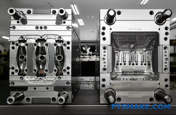
How do tooling design principles compare for Metal Injection Molding (MIM) and die casting?
The tool itself tells a story about the process. For MIM and die casting, the molds are engineered for vastly different environments.
Die casting tools face extreme heat and pressure. They must be incredibly robust.
MIM tools operate under much milder conditions. This allows for a different focus: managing precision and complex features during the process.
Mold Materials and Construction
The choice of steel is a critical first decision. It dictates the tool’s durability and performance under specific operational stresses.
In die casting, the tool must withstand the thermal shock of molten metal.
MIM tooling deals with an abrasive paste at lower temperatures. This difference is fundamental to their design and construction.
| Feature | Die Casting Tool Steel (e.g., H13) | MIM Tool Steel (e.g., P20, S7) |
|---|---|---|
| Primary Requirement | High-temperature strength, toughness | High hardness, wear resistance, polishability |
| Operating Temp. | ~650°C | ~200°C |
| Main Challenge | Resisting thermal fatigue and erosion | Resisting abrasive wear from feedstock |
The Critical Factor: Shrinkage vs. Force
The biggest design divergence isn’t just about strength. It’s about what happens to the part after molding. This is a key point in the metal injection molding vs die casting debate.
MIM Tooling: Designing for Shrinkage
MIM parts shrink significantly during sintering, often by 15-20%. The mold cavity must be precisely oversized to compensate.
At PTSMAKE, our tooling engineers focus heavily on this calculation. The tool is not built for the final part size. It’s built for the "green" part, anticipating this transformation.
Die Casting Tooling: Bracing for Impact
Die casting tools don’t worry about shrinkage to the same degree. Their primary challenge is enduring immense injection pressures and thermal stress.
The mold construction is heavier, with robust cooling channels. These are essential to manage heat and prevent premature tool failure from thermal fatigue5.
Lifecycle and Maintenance Comparison
A tool’s lifecycle directly impacts the cost per part. Die casting tools, due to their harsh environment, have a different wear pattern than MIM tools.
| Aspect | Die Casting Tool | MIM Tool |
|---|---|---|
| Typical Lifespan | 100,000 – 500,000 shots | 500,000 – 1,000,000+ shots |
| Primary Wear Factor | Heat checking, erosion, soldering | Abrasive wear on gates and cavities |
| Maintenance Needs | Frequent polishing, stress relief, weld repair | Less frequent, focused on cleaning and gate wear |
Die casting tools require robust steels to endure extreme heat and pressure. In contrast, MIM tools are engineered with ultra-high precision to account for significant, predictable part shrinkage, influencing material choice, construction, and the tool’s operational lifespan.
What geometric complexities are better suited for each process ?
When comparing metal injection molding vs die casting, geometry is a decisive factor. The choice hinges on the part’s complexity and size.
MIM shines with small, highly complex 3D shapes. It easily handles features like undercuts, cross-holes, and fine surface textures in a single process.
This often eliminates the need for later assembly. Die casting, however, is better for larger parts with less intricate, more 2.5D features.
| Feature | Metal Injection Molding (MIM) | Die Casting |
|---|---|---|
| Undercuts | Easily incorporated | Difficult or adds significant cost |
| Cross-holes | Achievable in one step | Often requires secondary machining |
| Surface Details | Highly intricate and fine | Simpler, less detailed |
| Part Size | Ideal for small to medium | Suited for medium to very large |
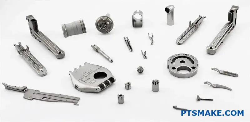
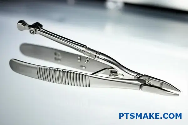
Let’s look at real-world examples. In past projects at PTSMAKE, we’ve used MIM to produce components for advanced surgical instruments.
These parts required intricate internal channels, external threads, and complex ergonomic grips. MIM created these as a single, solid piece. This integration is impossible to achieve with die casting without extensive assembly. It simplifies the supply chain and enhances the product’s reliability. The process creates parts with excellent isotropic properties6, which is critical for medical devices.
Conversely, die casting is the champion for larger-scale components. Think of an automotive clutch housing or a large heatsink for electronics. These parts demand structural integrity over a large area but have simpler geometric needs.
Their complexity lies in their overall form, not in micro-features. While they may have ribs and bosses, they generally avoid the deep undercuts or tiny cross-holes that are MIM’s specialty.
| Application Example | Best Process | Key Geometric Advantage |
|---|---|---|
| Surgical Tool Jaws | MIM | Integrated serrations and pivot points. |
| Watch Casing | MIM | Intricate logos and details in one piece. |
| Engine Block | Die Casting | Large, structurally sound forms. |
| Laptop Chassis | Die Casting | Thin walls over a large surface area. |
In short, MIM is your solution for small, feature-rich parts where you can eliminate assembly. Die casting is the economical choice for larger parts where the primary complexity is in the overall shape, not the fine details.
Compare the typical surface finish capabilities (Ra) of both methods between Metal Injection Molding (MIM) and Die Casting.
Surface finish is a critical factor. It impacts both the look and function of a part. When choosing between metal injection molding vs die casting, this is a key difference.
MIM typically produces a much smoother surface right out of the mold. This is due to the fine metal powders used. They perfectly replicate the polished surface of the mold tool. Die casting often results in a rougher initial finish.
Here’s a quick comparison based on our project data.
| Manufacturing Method | Typical As-Molded Surface Finish (Ra) |
|---|---|
| Metal Injection Molding (MIM) | 0.8 – 1.6 µm |
| Die Casting | 1.6 – 6.3 µm (or higher) |
This difference often means less secondary processing for MIM parts.
Let’s explore why these finishes differ so much. The secret for MIM lies in its feedstock. It’s a mix of fine metal powder and a binder. This paste-like material flows smoothly into the mold cavity. It captures every fine detail of the polished tool surface.
This process results in a consistent, high-quality finish across the part. At PTSMAKE, we often see clients choose MIM specifically to avoid extra polishing steps. This saves both time and cost.
Die casting, however, involves injecting molten metal under high pressure. This turbulent flow can create imperfections on the surface. Factors like cooling rates and the use of a mold release agent7 also affect the final texture.
While die casting is excellent for many applications, achieving a smooth, cosmetic surface usually requires secondary operations. This can include sandblasting, polishing, or coating.
| Factor | Metal Injection Molding (MIM) | Die Casting |
|---|---|---|
| Material State | Fine powder feedstock (paste) | Molten metal |
| Mold Filling | Laminar, gentle flow | Turbulent, high-pressure flow |
| Tool Surface Replication | Very high fidelity | Good, but less precise |
| Secondary Finishing Need | Often none for cosmetics | Usually required for cosmetics |
Ultimately, the right choice depends on your specific surface requirements.
MIM excels in delivering a superior as-molded surface finish (0.8-1.6 µm Ra). This often eliminates post-processing steps. Die casting produces a rougher initial surface, typically requiring secondary operations for cosmetic applications, making MIM a better choice for high-finish parts.
What are the typical dimensional tolerance ranges for each technology ?
When precision is non-negotiable, the numbers speak for themselves. The choice between MIM and die casting often comes down to the required dimensional accuracy.
MIM is known for its incredible precision. It consistently holds very tight tolerances, often around ±0.3% to ±0.5% of the dimension. This makes it ideal for complex, small parts.
Die casting, while fast and cost-effective, typically has wider tolerances. A general rule is ±0.1mm for the first 25mm. Let’s compare them directly.
| Feature | Metal Injection Molding (MIM) | Die Casting |
|---|---|---|
| Typical Tolerance | ±0.3% to ±0.5% | ±0.1mm for first 25mm |
| Consistency | High | Moderate to High |
| Best For | High-precision parts | General purpose parts |
This difference is critical for your final component’s function.
A Deeper Look at Tolerance Implications
Understanding the numbers is one thing. Applying them to your project is what matters. The tolerance capabilities of each process directly impact your design, cost, and production workflow.
MIM: Precision Straight from the Mold
With MIM, we can often produce parts that are ready to use right after sintering. This is because the process can achieve a Net-shape8 or near-net-shape condition.
This capability significantly reduces or even eliminates the need for secondary machining. At PTSMAKE, we leverage this to deliver highly complex components that meet stringent specifications without additional steps. This is a key factor in the metal injection molding vs die casting decision for intricate designs.
Die Casting: Planning for Post-Machining
Die casting’s wider tolerances mean that for critical features like threads or very precise hole diameters, you must plan for post-machining. This is not a drawback but a standard part of the process.
The initial part is produced quickly and economically. Then, specific features are machined to meet the tightest tolerance requirements. This two-step approach is often the most cost-effective solution for larger parts or those with only a few critical dimensions.
| Process | Post-Machining Need | Typical Use Case |
|---|---|---|
| MIM | Often not required | Medical devices, electronics |
| Die Casting | Common for critical features | Automotive housings, enclosures |
MIM excels at producing net-shape parts with tight tolerances, reducing post-processing needs. Die casting offers wider tolerances, suitable for many applications, with secondary machining planned for critical dimensions. Your project’s specific requirements will determine the best fit.
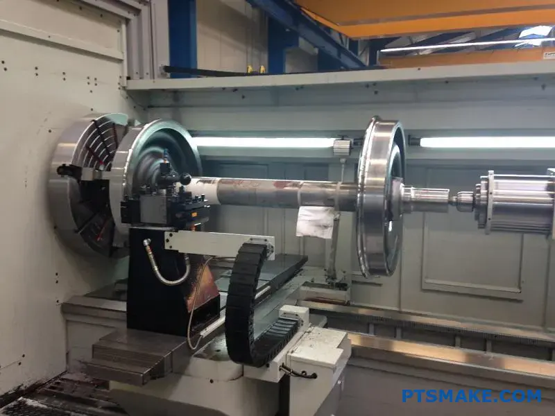
How does part size and weight limitation compare between the two between Metal Injection Molding (MIM) and Die Casting?
When choosing a manufacturing process, scale matters. The size and weight of your part often make the decision for you.
Metal Injection Molding (MIM) is perfect for small, complex parts. Think of components weighing less than 0.1 grams up to about 100 grams.
Die casting, on the other hand, excels at producing much larger and heavier items. It can handle parts from a few grams to many kilograms. This makes it ideal for structural components.
Here’s a quick comparison:
| Feature | Metal Injection Molding (MIM) | Die Casting |
|---|---|---|
| Typical Weight | <0.1g to 100g | A few grams to >10kg |
| Best For | Small, intricate components | Large, structural parts |
Understanding the Physical Boundaries
The size limitations for these processes are not arbitrary. They stem directly from the underlying physics of each method. When evaluating metal injection molding vs die casting, these physical limits are a primary consideration.
The MIM Envelope
MIM is rooted in powder metallurgy. The feedstock, a mix of metal powder and binder, can become costly for very large parts. More importantly, the post-molding steps present challenges.
The debinding and sintering stages are critical. During this phase, the part shrinks uniformly to its final density. For larger parts, managing this shrinkage without causing distortion or cracks is incredibly difficult. The sintering9 process works best on a smaller scale.
The Die Casting Domain
Die casting involves forcing molten metal into a mold under high pressure. The size limits here are mostly mechanical. They depend on the size of the die casting machine and its clamping force.
At PTSMAKE, our experience shows that die casting’s capacity for large parts is a key advantage. It enables the production of items like automotive housings and large enclosures, which are simply not feasible with MIM.
| Limiting Factor | Metal Injection Molding (MIM) | Die Casting |
|---|---|---|
| Process Core | Powder Metallurgy & Sintering | Molten Metal & High Pressure |
| Key Constraint | Debinding and Shrinkage Control | Mold Size & Machine Tonnage |
| Ideal Application | High-volume small, complex parts | High-volume large, strong parts |
In summary, MIM is the specialist for small, precise parts, typically under 100g. For larger and heavier components requiring structural integrity, die casting is the clear winner, capable of producing parts that weigh several kilograms. Your part’s scale dictates the best process.
What secondary operations are commonly required for each process ?
After a part is formed, the job is not always done. Both MIM and die casting often need secondary operations. These extra steps ensure the final part meets all specifications.
However, the type and extent of these operations differ greatly. Die casting usually requires more significant work. MIM, on the other hand, is designed to minimize these steps from the start.
Quick Comparison of Post-Processing
| Operation | Die Casting | Metal Injection Molding (MIM) |
|---|---|---|
| Trimming | Almost always required | Rarely needed |
| Machining | Often necessary for features | Only for ultra-high precision |
| Heat Treatment | Sometimes for strength | Part of the core process (sintering) |
| Surface Finish | Common | Common |
This table shows the fundamental difference. Let’s explore why these differences exist.
Why Secondary Operations Differ
The need for post-processing links directly to how each part is made. Understanding this helps in choosing the right process for your project.
Die Casting: The Need for Cleanup
Die casting uses high pressure to inject molten metal into a mold. This force can cause material to seep into the mold’s parting lines. This excess material is called flash.
Trimming flash, runners, and overflows is a standard step. It is essential for the part to function correctly. This is often a manual or automated process that adds time and cost. Sometimes, critical features need CNC machining to meet tight tolerances that casting alone cannot achieve.
MIM: Designing for Less Post-Work
MIM parts, often called "green parts" before sintering, are much closer to their final shape. The process is inherently more precise. This focus on near-net-shape manufacturing is a key advantage.
However, some minor operations may still be needed. For instance, coining10 can be used to improve dimensional accuracy or flatten a surface. Light machining might be required for features with tolerances that even MIM cannot hold.
Common Ground: Surface Treatments
Both MIM and die-cast parts can receive various surface treatments. The choice depends entirely on the application’s needs for appearance, corrosion resistance, or wear resistance.
| Treatment Purpose | Applicable Processes | Examples |
|---|---|---|
| Aesthetics | Both | Plating, Painting, Polishing |
| Corrosion Resistance | Both | Anodizing, Coating, Plating |
| Wear Resistance | Both | Hard Coating, Nitriding |
At PTSMAKE, we help clients evaluate these post-processing needs early in the design phase. This ensures the chosen process, whether it’s metal injection molding vs die casting, aligns with budget and performance goals.
Die casting parts usually need considerable trimming and machining after molding. In contrast, MIM is designed to produce near-net-shape components, which greatly reduces the need for secondary work. Both processes, however, can share similar surface finishing options.
Compare the mechanical strength and hardness of typical parts between Metal Injection Molding (MIM) and Die Casting.
When choosing between manufacturing processes, mechanical properties are critical. Metal Injection Molding (MIM) parts often outperform die cast parts in strength and hardness. This is not by chance.
The Density Advantage
MIM produces parts with very high density. This is usually 95-99% of theoretical density. This near-solid structure provides excellent mechanical strength. Die casting can sometimes trap gas, leading to porosity.
Finer Grain Structure
The fine metal powders used in MIM create a fine-grained microstructure. This structure contributes significantly to higher hardness and overall durability compared to die casting.
A Deeper Look at Structural Integrity
The core difference in the metal injection molding vs die casting debate often comes down to internal structure. The MIM process involves sintering fine metal powders at high temperatures. This fuses the particles together, creating an almost completely solid part. This minimizes internal defects.
Die casting, by contrast, injects molten metal into a mold under high pressure. While fast, this can trap air or gases, creating porosity. These tiny internal voids can become stress points, potentially leading to part failure under load.
The Role of Heat Treatment
Heat treatment can enhance the properties of parts from both processes. However, MIM parts, especially steels, see a more significant improvement. At PTSMAKE, we often use heat treatment to dramatically increase the hardness and wear resistance of MIM steel components for demanding applications.
The table below shows a typical comparison for a steel alloy after processing.
| Property | MIM (As-Sintered) | MIM (Heat-Treated) | Die Casting (As-Cast) |
|---|---|---|---|
| Tensile Strength (MPa) | 550 | 1200+ | ~300 |
| Hardness (HRC) | 25 | 45+ | N/A (lower scale) |
| Ductility11 (% Elongation) | 15% | 5% | 10% |
As our test results show, heat-treated MIM steel achieves properties comparable to wrought materials. This makes it a powerful choice for complex, high-strength parts. Die cast parts are more limited in their response to heat treatment.
MIM’s high-density, fine-grained structure gives it a clear advantage in strength and hardness over as-cast die cast parts. Heat treatment further amplifies these benefits, particularly for MIM steels, making it a superior choice for high-performance applications.
How does production volume affect the viability of each process ?
Choosing between manufacturing processes often comes down to economics. Both Metal Injection Molding (MIM) and Die Casting require significant upfront tooling investment. This initial cost makes them best suited for high-volume production.
Mapping the Economic Zones
MIM finds its sweet spot in a wide range. It becomes competitive for volumes starting around 10,000 parts and extends into the millions. This makes it very versatile.
Die Casting, however, truly shines at even higher volumes. Its faster cycle times make it more economical when production runs are massive.
Here’s a quick look at their ideal production volumes.
| Process | Typical Minimum Volume | Sweet Spot |
|---|---|---|
| Metal Injection Molding (MIM) | 10,000+ Parts | High-Volume |
| Die Casting | 50,000+ Parts | Very High-Volume |
Breaking Down the Cost-per-Part
The decision between metal injection molding vs die casting hinges on how costs are distributed. High initial tooling costs must be absorbed over the entire production run. The more parts you make, the lower the tooling cost per part.
The Impact of Tooling Costs
In our projects at PTSMAKE, we help clients understand this principle. The high cost of creating the mold or die is a major factor. Spreading this cost over a large number of units is key to achieving a competitive price per part. This process of cost distribution is known as amortization12.
Why Volume Shifts the Advantage
As production volume climbs into the hundreds of thousands or millions, other factors become more important than the initial tooling cost. This is where Die Casting often gains an economic edge.
Cycle Time and Material Efficiency
Die Casting typically has much faster cycle times than MIM. This means more parts can be produced in the same amount of time, reducing labor and machine costs per unit.
Additionally, the raw materials for Die Casting (metal ingots) are generally less expensive than the specialized metal powders used in MIM. While the difference per part may seem small, it adds up significantly over a massive production run.
This table shows how cost drivers change with volume.
| Cost Driver | Influence at 10,000 Parts | Influence at 1,000,000+ Parts |
|---|---|---|
| Tooling Cost | Very High | Low |
| Cycle Time | Moderate | Very High |
| Material Cost | Moderate | Very High |
Both processes are designed for high-volume production due to steep initial tooling costs. MIM is viable from 10,000 parts, while Die Casting becomes more cost-effective at extremely high volumes because of faster cycle times and lower material costs.
How do you estimate the break-even volume between the two processes?
Choosing the right manufacturing process is a critical decision. It directly impacts your project’s total cost. A simple calculation can provide a clear, data-driven answer.
This method helps you find the exact production volume where two processes cost the same.
The Break-Even Formula
The core idea is to compare total costs. The formula is straightforward:
Total Cost = Tooling Cost + (Piece Price × Volume)
This helps you decide between options like metal injection molding vs die casting.
Key Cost Factors
To use the formula, you need these three variables for each process.
| Cost Factor | Description |
|---|---|
| Tooling Cost | The one-time, upfront investment to create the mold or die. |
| Piece Price | The cost to produce a single part. |
| Volume | The total number of parts you plan to produce. |
This framework removes guesswork and bases your decision on solid numbers.

To find the break-even point, you must create a cost model for each process you’re considering. This is a fundamental step we guide our clients through at PTSMAKE.
Step 1: Formulate Equations
First, write down the total cost equation for each process. Let’s call them Process A and Process B.
- Total Cost A = Tooling Cost A + (Piece Price A × Volume)
- Total Cost B = Tooling Cost B + (Piece Price B × Volume)
This structure separates the high initial investment from the per-unit production cost. It clarifies how volume affects overall expense.
Step 2: Set Costs Equal
The break-even point is where the total costs are identical. So, you set the two equations equal to each other.
Tooling A + (Price A × V) = Tooling B + (Price B × V)
Now, you just solve for ‘V’ (Volume). This calculation shows the exact production quantity where it makes sense to switch from one process to another. This approach clarifies the long-term impact of Amortization13 on your initial tooling investment.
Here’s a comparison:
| Metric | Process A (e.g., Die Casting) | Process B (e.g., MIM) |
|---|---|---|
| Tooling Cost | Typically Higher | Typically Lower |
| Piece Price | Typically Lower | Typically Higher |
This calculation justifies your choice for a specific production quantity.
The break-even calculation gives you a precise volume where the total costs of two processes match. Below this volume, one process is cheaper; above it, the other is. This makes your manufacturing decision quantifiable and defensible.
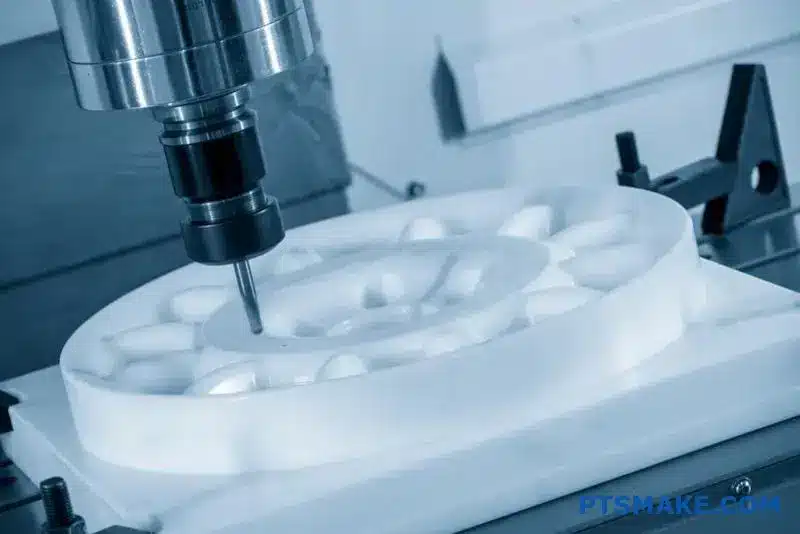
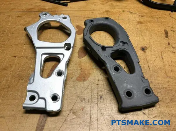
What prototyping strategies are effective before committing to tooling between Metal Injection Molding (MIM) and Die Casting?
Choosing the right prototype saves time and money. It is a critical step before investing in production tooling. Your choice depends entirely on your specific testing needs.
For both MIM and die casting, different paths exist. Each path offers unique trade-offs in speed, cost, and material accuracy. This evaluation is key.
Key Prototyping Approaches
| Process | Primary Method | Key Benefit |
|---|---|---|
| MIM | Binder Jet 3D Printing | Speed |
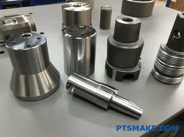
| Die Casting | CNC Machining | Form & Fit |
At PTSMAKE, we guide clients through these options to ensure the final design is perfect.
Evaluating MIM Prototyping Options
For Metal Injection Molding, two main options exist. Binder jet 3D printing is very fast for creating complex shapes. It’s excellent for early design verification. The material properties might not perfectly match a final MIM part.
Another approach is machining a part from a green or pre-sintered block of MIM material. This gives you a prototype with nearly identical mechanical properties. It’s perfect for functional testing where material strength is a primary concern.
Evaluating Die Casting Prototyping Options
For die casting, CNC machining is a popular method. We can machine a prototype from a solid block of the exact target alloy. This is ideal for checking form and fit. However, the material’s grain structure will differ from a cast part.
A more advanced strategy is soft prototype tooling. This involves creating a simplified mold from steel or aluminum. It allows for a small batch of actual cast parts. These prototypes provide the most accurate feedback. This process involves creating a part from a sintered block14 of MIM material for testing.
| Method | Best For | Speed | Material Accuracy |
|---|---|---|---|
| Binder Jetting (MIM) | Complex Geometry | Fast | Moderate |
| Machined MIM Block | Functional Testing | Slow | High |
| CNC Machining (Die Cast) | Form & Fit | Fast | Low (grain structure) |
| Soft Tooling (Die Cast) | Process Validation | Moderate | High |
Prototyping for MIM often involves binder jetting for speed or machining a block for material accuracy. For die casting, CNC machining validates form, while soft tooling provides a realistic preview of the final cast part, balancing cost and fidelity effectively.
How do you approach converting a design from one to another ?
Converting a design is more than just changing a file. It demands a systematic process. This ensures the final part meets all functional and quality requirements.
At PTSMAKE, we follow a structured approach. It helps us avoid costly errors and delays. This checklist-driven method is crucial for success.
Initial Conversion Checklist
| Consideration | MIM Conversion | Die Casting Conversion |
|---|---|---|
| Geometry | Embrace complexity | Simplify for mold release |
| Walls | Optimize for consistency | Taper for draft |
| Features | Combine parts | Reduce undercuts |
This careful planning makes the transition between technologies smooth and efficient.
A systematic conversion process is essential for success. It involves a detailed review of the original design’s intent and manufacturing constraints. We always start with a thorough Design for Manufacturability (DFM) analysis tailored to the target process. This highlights potential issues early.
From Machined Part to MIM
When converting from machining to MIM, we leverage MIM’s strengths. We add generous radii to corners to reduce stress and improve powder flow during molding. Wall thickness is optimized for uniformity to ensure successful sintering.
This is also a great chance to combine multiple machined components into a single, complex MIM part. This integration reduces assembly time and costs, while improving the part’s isotropic properties15. The debate of metal injection molding vs die casting often hinges on this ability to create complex, net-shape parts.
From MIM/Machining to Die Casting
Converting a design to die casting requires different thinking. The primary focus shifts to mold release and material flow.
Key Adjustments for Die Casting
| Design Element | Action Required | Reason |
|---|---|---|
| Vertical Walls | Add draft angles | To allow easy ejection from the mold |
| Undercuts | Simplify or eliminate | To reduce mold complexity and cost |
| Sharp Corners | Add fillets/radii | To improve metal flow and reduce stress |
| Material | Adjust for properties | Account for lower strength of casting alloys |
Each change is carefully calculated to ensure the final cast part is both functional and economical to produce.
A structured conversion process is critical. It involves specific design modifications tailored to the target technology, whether it’s MIM’s complexity or die casting’s mold-release requirements. This ensures optimal part performance and manufacturability.
Analyze a complex case study: a successful MIM component.
Let’s break down a real-world example. Consider a complex surgical tool jaw. This part is small yet demands incredible strength and precision.
Manufacturing it presents a huge challenge. Traditional methods like CNC machining would be extremely slow and costly. Each tiny feature would require a separate, difficult machining step.
Why MIM Was the Only Choice
MIM excels where other methods fail. It forms the entire complex part in one process. This eliminates most secondary operations, saving significant time and money.
| Feature | CNC Machining | Metal Injection Molding (MIM) |
|---|---|---|
| Complexity | Very Difficult / Costly | Excellent |
| Material Waste | High (Subtractive) | Very Low (Net-Shape) |
| Unit Cost | High | Low (in high volume) |
| Production Speed | Slow | Fast |
This makes MIM the only viable solution for mass-producing such intricate components.
Deconstructing the MIM Advantage
In past projects at PTSMAKE, we’ve seen how MIM transforms production for complex parts. The surgical jaw is a perfect case study demonstrating this. It highlights why MIM is often the superior choice.
Unmatched Geometric Freedom
The jaw has intricate grips, a pivot hole, and internal channels. MIM technology forms these features simultaneously in the molding stage. This "net-shape" capability is a game-changer. It creates parts that are nearly complete right out of the furnace.
High-Performance Material Selection
The surgical tool requires 17-4 PH stainless steel. This material offers high strength and excellent corrosion resistance. It is also biocompatible. When comparing metal injection molding vs die casting, this is a key differentiator. Die casting cannot process stainless steel. The MIM process, including sintering16, handles such advanced materials perfectly.
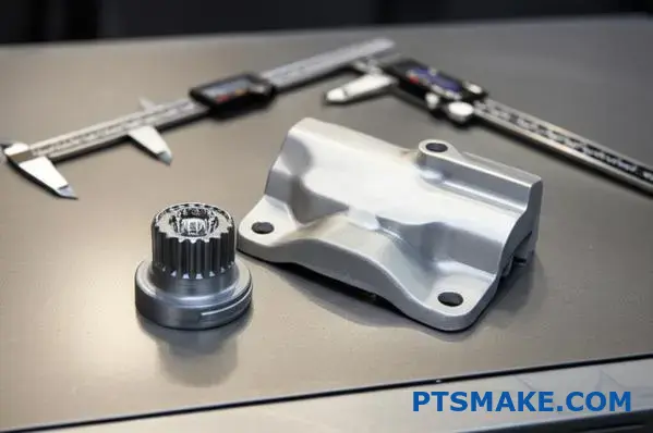
Precision and Consistency
Medical devices demand tight tolerances for reliable performance. Our analysis showed MIM can consistently hold tolerances as tight as ±0.3%. This level of precision is crucial for the tool’s function and is difficult to achieve cost-effectively with other methods.
| Requirement | How MIM Met It |
|---|---|
| Complex Geometry | Net-shape molding created all features in one step. |
| Material Needs | Processed 17-4 PH stainless steel with ease. |
| Tight Tolerances | Achieved ±0.3% dimensional accuracy consistently. |
| Cost Target | Eliminated extensive machining, reducing unit cost by over 50%. |
This case study shows why MIM was the ideal choice. It uniquely combines complex geometry, high-strength materials, and cost-efficiency for the surgical jaw. This made it superior to traditional machining for high-volume production.
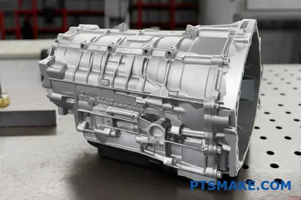
Analyze a complex case study: a successful die cast component.
Let’s look at a real-world example: an automotive transmission housing. This component is a perfect showcase for the benefits of die casting. It is complex, critical, and produced in very high numbers.
Key Success Factors
A transmission housing has strict requirements. It must be strong yet light. It also needs to handle intense heat. Die casting addresses these challenges effectively.
High production volumes make the process economical. The initial tooling cost is high, but it pays off over a long run.
| Requirement | Die Casting Advantage |
|---|---|
| Part Complexity | Creates intricate, net-shape parts |
| Lightweighting | Uses aluminum or magnesium alloys |
| High Volume | Extremely low cost per part |
| Heat Management | Excellent thermal properties |
A Deeper Analysis
Why was die casting the undisputed winner for this part? The decision comes down to a combination of material science, engineering needs, and production economics. Each factor points directly to this method.
Lightweight and Strong Materials
In the automotive industry, every gram matters. Using die-cast aluminum allows for a robust housing that protects a vehicle’s transmission. At the same time, it significantly reduces overall vehicle weight compared to traditional steel components. This improves fuel efficiency.
Superior Heat Dissipation
A transmission generates a lot of heat. The aluminum alloy’s high thermal conductivity17 is essential. The housing itself acts as a massive heat sink, pulling heat away from critical gears and fluids. This prevents overheating and extends the life of the transmission.
The Power of High-Volume Production
The initial investment for a die cast mold is substantial. This is a key point when considering metal injection molding vs die casting. However, when a manufacturer needs hundreds of thousands of identical parts, the cost per piece becomes incredibly low. This scale makes die casting unbeatable for mass-produced components.
| Process Comparison | Best for Housing? | Key Consideration |
|---|---|---|
| Die Casting | Yes, for mass production | High initial tool cost, low part price |
| CNC Machining | Only for early prototypes | Very high cost per part |
| Sand Casting | No, lacks precision/finish | Rough surface, slower cycle |
The transmission housing case study reveals die casting’s ideal fit. It balances the need for lightweight strength, effective heat dissipation, and complex geometry with the economic realities of high-volume automotive production, proving its value.
When would a hybrid approach or insert molding be optimal between Metal Injection Molding (MIM) and Die Casting?
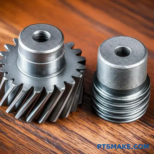
Sometimes, a single manufacturing process isn’t enough. What if your design demands the extreme wear resistance of steel but also the light weight of aluminum? This is where a hybrid approach shines.
Combining Strengths
We can leverage the best of both worlds. This involves insert-molding a MIM component into a larger die cast part. This creates a superior, multi-material product.
A Practical Example
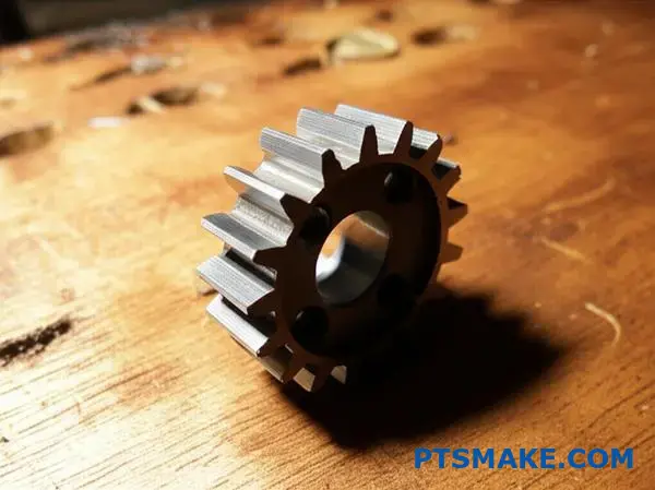
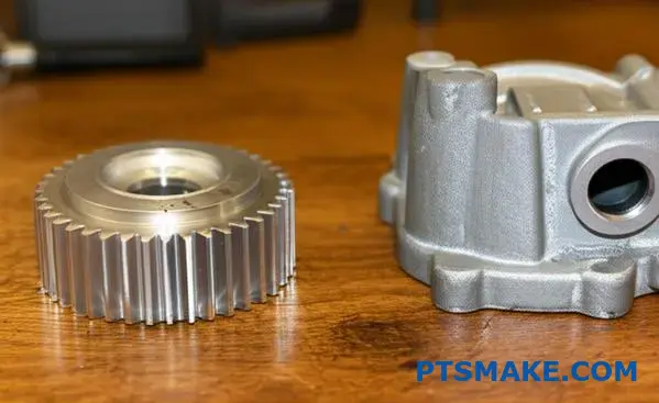
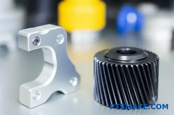
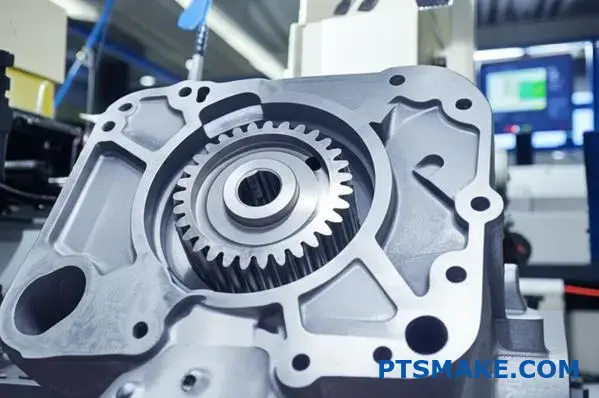
Imagine a high-strength MIM steel gear. It is placed inside a larger, lightweight aluminum die cast housing during production.
| Technology | Role in Hybrid Part | Key Benefit |
|---|---|---|
| MIM | Wear-Resistant Insert | Provides localized durability and strength. |
| Die Casting | Main Structural Body | Offers a lightweight frame and complex shape. |
This fusion optimizes performance and weight.
This advanced strategy is perfect for complex challenges. It allows us to create components that would otherwise be impossible or too expensive to manufacture from a single material. The discussion of metal injection molding vs die casting often overlooks these powerful combinations.
The Hybrid Process in Detail
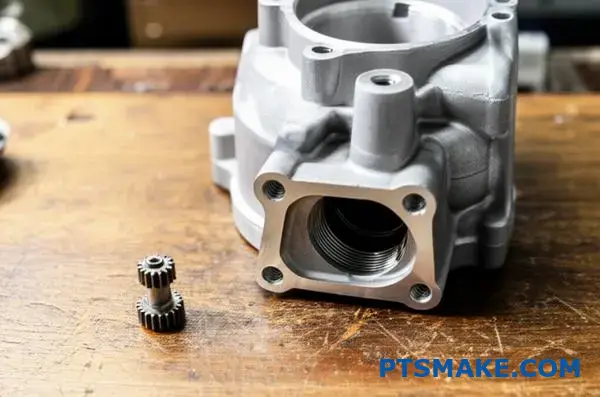
First, we produce the small, complex part using MIM. This is typically a wear-resistant steel or a specialty alloy. It provides strength exactly where it’s needed.
Next, this finished MIM part is placed into the die casting mold. It acts as a solid insert.
Molten metal, like aluminum or zinc, is then injected. It flows around the MIM insert, creating a robust mechanical lock as it solidifies. The quality of the interfacial bonding18 is critical for the final part’s integrity.
In our work at PTSMAKE, we’ve guided clients through this process. It helps them achieve significant weight reduction without sacrificing durability at critical points. The result is a single, integrated component with optimized properties.
Step-by-Step Hybrid Manufacturing
| Step | Process | Description |
|---|---|---|
| 1 | MIM Fabrication | A precise, high-density steel component is created and sintered. |
| 2 | Insert Placement | The finished MIM part is robotically placed into the die casting tool. |
| 3 | Overmolding | Molten aluminum is injected, enveloping the MIM insert. |
| 4 | Final Part | The final part is ejected, a seamless fusion of steel and aluminum. |
Combining MIM and die casting allows for the creation of superior multi-material parts. This hybrid approach leverages MIM’s precision strength and die casting’s lightweight structural capability, solving complex engineering challenges that a single process cannot address alone.
How do post-process heat treatments affect final part properties between Metal Injection Molding (MIM) and Die Casting?
The way a metal part responds to heat treatment is not universal. It depends heavily on its initial structure. This is a key differentiator when comparing metal injection molding vs die casting.
MIM parts behave very differently from die-cast ones. Their metallurgical responses open up diverse performance possibilities.
Metallurgical Response in MIM
MIM parts, especially steel, are sintered to near-full density. This structure allows them to be heat-treated much like traditional wrought steels. You gain access to a wide range of hardening and strengthening options.
Limited Options in Die Casting
Die-cast parts have a different internal structure. This limits the types of heat treatments they can undergo. While effective, the options are narrower compared to MIM.
| Feature | Metal Injection Molding (MIM) | Die Casting |
|---|---|---|
| Primary Process | Sintering | Casting |
| Typical Steel Treatment | Quench & Temper, Case Hardening | Not Applicable |
| Typical Aluminum Treatment | Not Common | Solution & Aging (T5, T6) |
| Property Enhancement | High Versatility | More Specific |
The core difference lies in the material’s journey. MIM parts are built from metal powders, fused together. This process creates a fine-grained, uniform microstructure. It is highly receptive to transformative heat treatments.
MIM: The Path to High Hardness
At PTSMAKE, we often use quenching and tempering on MIM steel parts. This dramatically increases hardness and tensile strength. We can tailor these properties precisely to a client’s needs.
Case hardening is another powerful tool for MIM. It creates a very hard surface while keeping the core ductile. This is perfect for wear-resistant components.
Die Casting: Enhancing Aluminum
For die-cast aluminum, the goals are different. Trapped gases and the cast structure prevent aggressive quenching.
However, treatments like T5 and T6 are very effective. The solution heat treatment19 followed by aging strengthens the part by precipitating fine particles within the aluminum matrix.
The results are significant but operate within a narrower window. You can improve strength and hardness, but not to the levels of hardened MIM steel.
Property Improvement Comparison
Based on our internal testing, the achievable property enhancements vary greatly.
| Property | MIM Steel (Post-Treatment) | Die Cast Aluminum (Post-Treatment) |
|---|---|---|
| Hardness Increase | Up to 300-400% | Up to 50-70% |
| Strength Increase | Up to 250-350% | Up to 40-60% |
| Ductility Change | Often Reduced | Slightly Reduced |
This shows why the process choice is critical. The debate over metal injection molding vs die casting often comes down to these final property requirements.
The fundamental metallurgical structure dictates heat treatment outcomes. MIM’s sintered steel offers a broad range of high-performance options, while die casting provides effective, though more limited, enhancements for alloys like aluminum. This is a critical consideration in part design.
Evaluate the lifecycle and sustainability impact of each process .
When choosing between manufacturing processes, sustainability is a key factor. The environmental impact isn’t just about one step. It’s about the entire lifecycle.
We must compare Metal Injection Molding vs Die Casting from start to finish. This includes energy, waste, and material use.
Energy Consumption Per Part
Energy usage is a primary concern. The initial process demands vary significantly. This table offers a quick comparison based on our internal analysis.
| Factor | Metal Injection Molding (MIM) | Die Casting |
|---|---|---|
| Initial Energy | High (furnace for debinding/sintering) | Moderate (melting metal) |
| Energy Per Part | Lower for small, complex parts | Lower for large, simple parts |
This comparison helps guide decisions. Your part’s size and complexity matter greatly.
A Deeper Look at the Lifecycle
Sustainability goes beyond just the energy used during production. We need to evaluate material efficiency and the potential for recycling throughout the entire process. Each method has distinct advantages here.
MIM requires significant energy for its multi-step process, including the crucial sintering20 phase. However, it excels at creating net-shape parts with minimal material waste. Runners and feedstock can often be reground and reused directly.
Die casting, on the other hand, is very efficient at recycling. Scrap, runners, and overflow are easily remelted. This closed-loop system is highly effective. The energy to remelt is much less than processing raw ore.
Sustainability Through Design
Design choices also impact the environment.
MIM: Parts Consolidation
MIM allows us to combine multiple components into a single, complex part. This reduces assembly steps and overall material usage, which is a big sustainability win.
Die Casting: Light-Weighting
Die casting is ideal for creating strong, lightweight parts from materials like aluminum and magnesium. Lighter parts, especially in automotive or aerospace, reduce fuel consumption over the product’s life.
| Aspect | Metal Injection Molding (MIM) | Die Casting |
|---|---|---|
| Waste Type | Runners, feedstock | Scrap, runners, flash |
| Recyclability | Runners are often reusable | Scrap is easily remelted |
| Design Advantage | Part consolidation | Light-weighting potential |
This lifecycle view provides a clearer picture of the metal injection molding vs die casting debate.
Both MIM and die casting offer unique sustainability benefits. MIM excels in minimizing initial material waste through part consolidation. Die casting’s strength lies in its highly efficient scrap recyclability and potential for creating lightweight components that save energy during use.
Ready to Optimize Your Manufacturing? PTSMAKE Delivers Precision!
Unlock hassle-free quotes and expert guidance for both metal injection molding and die casting projects. Contact PTSMAKE today—our team is ready to help you achieve tighter tolerances, seamless production, and exceptional value from prototype to mass production. Request your tailored quote now!

Learn how feedstock flow behavior is critical for creating high-quality, defect-free molded parts. ↩
Understand this crucial step that transforms the "green" part by removing the polymer binder before final sintering. ↩
Understand how a material’s directional properties can impact your part’s design and structural integrity. ↩
Explore how this powder metallurgy process enables complex, high-strength parts. ↩
Learn how repeated heating and cooling cycles impact the structural integrity of tool steels. ↩
Learn how this material quality affects part strength and performance in critical applications. ↩
Learn how different agents can impact part quality, ejection, and final surface texture. ↩
Learn how achieving net-shape components can simplify your supply chain and lower your total manufacturing costs. ↩
Learn how this heating process solidifies metal powders into strong, dense parts. ↩
Learn how this process improves part accuracy and surface properties. ↩
Click to understand how this material property affects component performance under stress. ↩
Learn how tooling costs are spread across a production run to determine the final cost-per-part. ↩
Learn how spreading tooling costs over production volume impacts your final piece price. ↩
Understand how a sintered block mimics final MIM part properties for more accurate functional testing. ↩
Learn how uniform material strength in all directions impacts your part’s performance and design. ↩
Discover how this heating process transforms metal powder into a solid, high-density part. ↩
Discover why this material property is vital for designing components that manage thermal stress. ↩
Learn how the bond between dissimilar materials is created and optimized for maximum part strength. ↩
Learn how this process enhances the mechanical properties of aluminum alloys. ↩
Understand this key thermal process that defines MIM part strength and its energy profile. ↩