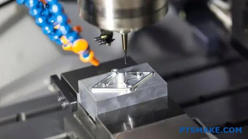
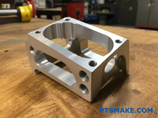
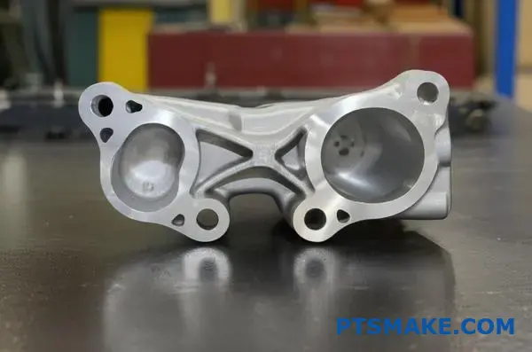
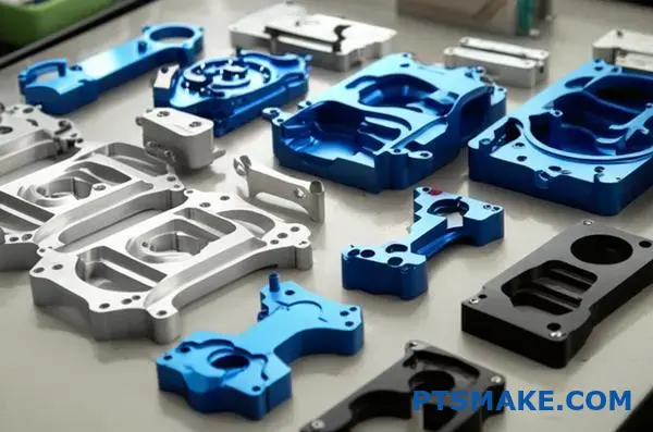
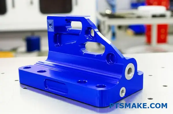
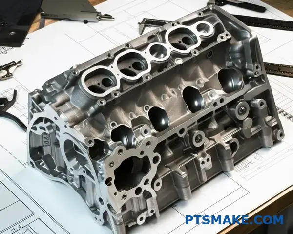
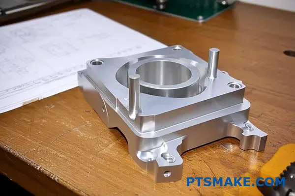
Complex CNC machined parts often fail during production because engineers overlook critical design constraints. Your perfectly designed component becomes a manufacturing nightmare when tool access is impossible, tolerances are unrealistic, or geometry creates insurmountable workholding challenges.
Complex CNC machining success depends on balancing part functionality with manufacturing constraints through strategic design choices, appropriate material selection, and early collaboration between engineers and machinists to optimize both performance and cost-effectiveness.
I’ve worked with hundreds of engineers at PTSMAKE who learned these lessons the hard way. Some discovered their "simple" design changes could double machining time, while others found that minor geometry adjustments saved thousands in tooling costs. The difference between a smooth production run and a costly redesign often comes down to understanding these fundamental principles before you commit to manufacturing.
Key Design Considerations for Complex CNC Machined Parts?
Have you ever finalized a complex part design, only to be told it’s nearly unmanufacturable or will shatter the budget? That back-and-forth drains time, energy, and stalls entire projects.
Key design considerations for complex CNC machined parts involve a deep understanding of machine capabilities, designing part geometry for manufacturability, and fostering early collaboration with machinists. This alignment prevents costly redesigns, shortens lead times, and ensures the final part meets both functional and budgetary goals.
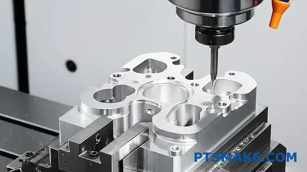
Understanding Machine Capabilities: 3-Axis vs. 5-Axis
The first checkpoint in designing any complex part is understanding the equipment that will create it. The capabilities of a 3-axis machine versus a 5-axis machine are worlds apart, and this choice fundamentally impacts your design freedom. A 3-axis machine works on the X, Y, and Z planes. It’s perfect for simpler parts with features that can be accessed from the top. However, if your part has undercuts, angled holes on multiple faces, or complex organic surfaces, a 3-axis machine will require multiple setups. Each time the part is manually re-fixtured, you introduce the risk of error and significantly increase labor time.
On the other hand, 5-axis machining adds two rotational axes. This allows the cutting tool to approach the workpiece from a much wider range of angles, often completing an entire part in a single setup. For truly complex CNC machining, this is a game-changer. It unlocks the ability to create intricate geometries that would be impossible or prohibitively expensive otherwise. The machine’s degrees of freedom1 directly correlate to the complexity it can handle efficiently. In our work at PTSMAKE, we’ve seen designs that would require six different setups on a 3-axis machine be completed in one seamless operation on a 5-axis center. This not only improves precision by eliminating tolerance stacking but can also reduce the final piece-part price despite the higher machine hour rate.
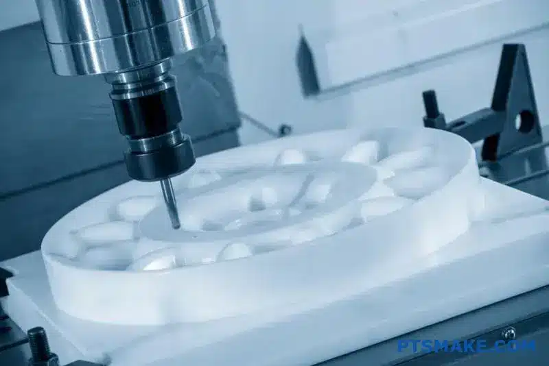
How Part Geometry Dictates Manufacturability
Your part’s geometry is the blueprint the machine follows, and some blueprints are much easier to read than others. Features that look simple in a CAD model can present major challenges on the shop floor.
- Internal Corners: Cutting tools are round, meaning they cannot create perfectly sharp internal corners. Every internal corner must have a radius at least as large as the tool that will cut it. Designing a smaller radius requires a smaller, more fragile tool, which increases machining time and the risk of tool breakage.
- Deep Pockets: The ideal ratio for a pocket’s depth to the tool’s diameter is around 3:1. Pushing beyond this requires specialized long-reach tooling that is prone to vibration and deflection, compromising surface finish and accuracy.
- Thin Walls: Walls that are too thin relative to their height can vibrate during machining, leading to chatter and poor dimensional accuracy. They can also warp from the heat and stress of the cutting process.
A simple comparison shows how machine choice is linked to geometry.
| Feature | 3-Axis Machining | 5-Axis Machining |
|---|---|---|
| Complexity | Best for simpler, planar geometries | Ideal for complex curves and undercuts |
| Setups | Often requires multiple manual setups | Can often complete parts in a single setup |
| Accuracy | Risk of tolerance stacking from re-fixturing | Higher accuracy due to single clamping point |
| Ideal For | Brackets, plates, and prismatic parts | Impellers, medical implants, aerospace components |
Thinking about these physical limitations during the design phase is the essence of Design for Manufacturability (DFM).
The Impact of Design Choices on Cost and Lead Time
Every line, curve, and tolerance note you add to a drawing has a direct impact on the final cost and delivery schedule. It’s a reality that can be hard to quantify from a design perspective alone, but from a machinist’s view, the connection is crystal clear. The goal isn’t to compromise the design’s function but to achieve it in the most efficient way possible. For instance, specifying an unnecessarily tight tolerance on a non-critical feature forces us to use slower cutting speeds, more frequent tool changes, and extensive CMM inspection cycles. Loosening that same tolerance, where functionally acceptable, could cut machining time for that feature by half.
The same principle applies to surface finish. A standard machined finish is relatively quick to produce. However, requesting a mirror-like finish (e.g., Ra 8 µin) requires additional fine-milling passes, and potentially secondary processes like lapping or polishing, each adding significant time and cost. It’s crucial to ask: does this surface need to be this smooth for functional reasons, or is it purely aesthetic? Material selection is another huge factor. Machining a part from aluminum 6061 is straightforward. Making that same part from Inconel or Titanium, materials common in aerospace, dramatically increases tool wear and reduces cutting speeds, which in turn drives up both cost and lead time.
Balancing Complexity with Practicality
The most successful projects are born from balancing design intent with manufacturing reality. In my experience, this balance is rarely found in isolation. It requires open communication and collaboration between the designer and the machinist. The best time to have this conversation is at the concept stage, not after the design has been finalized and released. At PTSMAKE, we often engage with our clients’ engineering teams early on. In a recent project, a client designed a housing with several deep pockets. Our initial analysis showed it would require specialized tooling and long cycle times. By collaborating, we identified that a minor adjustment to the pocket depths and corner radii—changes that had no impact on the part’s function—allowed us to use standard tooling and reduce the cycle time by an estimated 30%. This simple, early-stage dialogue saved thousands of dollars over the production run.
This table illustrates the direct relationship between design choices and their manufacturing consequences.
| Design Choice | Impact on Cost | Impact on Lead Time |
|---|---|---|
| Tight Tolerances (e.g., ±0.001") | High | Increased |
| Fine Surface Finish (e.g., Ra 16) | Moderate to High | Increased |
| Exotic or Hard Materials | Very High | Variable (procurement and machining) |
| Non-Standard Radii/Features | Moderate | Increased (custom tooling) |
Ultimately, a manufacturable design is an intelligent design. It achieves all functional requirements while respecting the physical processes that bring it to life.
Mastering complex CNC machining requires a holistic approach that goes beyond the CAD model. It hinges on understanding the interplay between your part’s geometry and the machine’s capabilities. Seemingly small choices about tolerances, corner radii, and surface finishes have an outsized impact on cost and timelines. The most powerful tool at your disposal is early collaboration. Engaging with your manufacturing partner from the outset transforms potential roadblocks into opportunities for innovation and efficiency, ensuring your vision becomes a reality.
Optimizing Geometry: Avoiding Unnecessary Complexity.
Have you ever finalized a design, only to find the manufacturing quote was double what you expected? That beautiful, intricate feature might be the culprit, silently inflating your costs.
Optimizing part geometry is about striking a critical balance. It involves methodically removing non-essential features that add machining time and cost, without compromising the part’s core function, strength, or reliability. This is the key to efficient complex CNC machining.
The True Cost of Non-Essential Features
In complex CNC machining, every line in a CAD model translates to a machine movement, a tool path, or a setup change. Unnecessary features don’t just add a little time; they create a compounding effect that drives up costs and lead times. The more complex the geometry, the more specialized tooling, programming, and operator attention are required.
Functionality vs. Aesthetics: A Critical Evaluation
The first step is to question every feature: does it serve a functional purpose? A feature is functional if it’s essential for the part’s assembly, alignment, strength, or operation. Aesthetic features, while sometimes important for branding, often provide little to no engineering value and can be major cost drivers.
Think about a simple bracket. A functional feature would be a mounting hole with a specific diameter and tolerance. An aesthetic one might be an elaborately curved edge that doesn’t improve strength. We often work with clients at PTSMAKE to distinguish between the two. One project involved a housing where a deep, narrow pocket was designed for purely visual reasons. By changing it to a simpler, wider recess, we reduced machining time by nearly 30% without affecting the product’s performance at all. This kind of analysis is central to our Design for Manufacturability (DFM) process. It’s about making smart choices that respect both the design intent and the manufacturing reality. A carefully selected datum2 can also simplify the entire setup process, reducing potential errors.
Analyzing Feature Impact
To help decide, you can create a simple evaluation matrix. This forces you to justify each element of your design.
| Feature | Primary Purpose | Functional Necessity (1-5) | Cost Impact (1-5) | Decision |
|---|---|---|---|---|
| M4 Mounting Holes | Assembly | 5 (Essential) | 1 (Low) | Keep |
| 0.2mm Fillet | Stress Relief | 4 (High) | 2 (Medium) | Keep |
| Engraved Logo | Branding | 1 (Aesthetic) | 4 (High) | Simplify/Remove |
| Internal Ribs | Stiffness | 5 (Essential) | 3 (Medium) | Keep |
This process helps separate the "must-haves" from the "nice-to-haves," guiding you toward a more streamlined and cost-effective part.
Designing for Structural Integrity
Beyond just removing features, optimizing geometry is about designing for strength and durability. An over-machined part is a weak part. Every cut removes material, and if not planned carefully, it can compromise the structural integrity of the final component, leading to failure under load. This is especially critical for high-performance applications in industries like aerospace and medical devices.
Avoiding Stress Concentrators
Sharp internal corners are one of the biggest enemies of structural integrity. They act as stress concentrators, creating points where force is amplified, often leading to cracks and fractures. Even if a corner seems minor on a CAD screen, it can become a major failure point in the real world.
The solution is simple: add generous fillets or radii to all internal corners. This helps distribute stress more evenly across the geometry. In our experience, a slightly larger fillet can dramatically increase a part’s fatigue life with a minimal impact on machining time. In fact, it often simplifies the process, as larger tools can be used.
The Dangers of Excessive Material Removal
It can be tempting to remove as much material as possible to reduce weight. However, this must be done strategically. Hollowing out a part without proper support structures, like internal ribs or gussets, can make it flimsy and prone to warping, both during and after machining.
Consider the following when designing for material removal:
| Bad Practice | Consequence | Good Practice | Benefit |
|---|---|---|---|
| Sharp internal corners | High stress concentration | Generous internal radii | Distributes stress, improves tool life |
| Thin, unsupported walls | Warping, vibration, weakness | Add ribs or thicken walls | Increases stiffness and stability |
| Deep, narrow pockets | Difficult to machine, tool breakage | Widen pockets, reduce depth | Faster machining, better surface finish |
In past projects with clients, we’ve used simulation tools to identify high-stress areas before a single piece of metal is cut. This allows us to suggest adding material in critical zones while removing it from low-stress areas. The result is a part that is both lightweight and strong—the ideal outcome for any complex CNC machining project. This thoughtful approach ensures the part not only looks like the design but performs flawlessly under pressure.
Optimizing geometry is a foundational step in successful complex CNC machining. It’s not about compromising your design, but rather enhancing it by critically evaluating every feature for its functional necessity. By distinguishing between aesthetic wants and functional needs, you can significantly reduce manufacturing costs and lead times. Furthermore, focusing on structural integrity by avoiding stress concentrators and planning material removal carefully ensures your final part is not just manufacturable, but also strong and reliable in its application.
Managing Wall Thickness and Feature Proportions.
Have you ever designed a part with walls so thin they warped during machining or features so tall they chattered, ruining the final piece?
Properly managing wall thickness and feature proportions is fundamental. This means respecting material-specific minimums and using stable height-to-width ratios to prevent vibration, ensuring the final component achieves the tight tolerances required in complex CNC machining.
When we talk about complex CNC machining, the conversation often centers on multi-axis machines and tight tolerances. However, the most fundamental principles of design for manufacturability (DFM) are just as critical. Wall thickness is one of those core principles. If walls are too thin, they can’t withstand the cutting forces. This leads to deflection, vibration, and an inability to hold tolerances. In some cases, the part can even warp or break right on the machine. Every material behaves differently, which is why establishing a baseline for minimum thickness is the first step.
The Golden Rule: Material-Specific Minimums
You can’t apply a one-size-fits-all rule. Metals are generally more rigid than plastics, allowing for thinner walls. But even within metals, there are significant differences. A strong material like stainless steel can support thinner features than a softer material like aluminum. At PTSMAKE, we often advise clients based on extensive testing and project experience. For instance, while you might get away with a 0.5mm wall in aluminum for a small feature, we recommend a safer minimum of 0.8mm for general applications to ensure stability and repeatability. Plastics are even more sensitive to heat and cutting forces, requiring thicker walls to prevent melting or warping. This is where the true challenge of chatter3 comes into play; it’s not just noise, it’s a physical sign that the part or tool is vibrating uncontrollably, leading to a poor surface finish and dimensional inaccuracy.
General Guidelines for Minimum Wall Thickness
Here’s a quick reference table based on what we typically see in successful projects. These are starting points, and factors like feature size and part geometry can influence the final decision.
| Material | Recommended Minimum Wall Thickness | Notes |
|---|---|---|
| Aluminum (6061) | 0.8 mm (0.031 in) | Strong yet light, but can deflect if too thin. |
| Stainless Steel (304/316) | 0.75 mm (0.030 in) | High rigidity allows for thinner walls. |
| ABS Plastic | 1.5 mm (0.060 in) | Prone to warping from heat during machining. |
| Polycarbonate (PC) | 1.0 mm (0.040 in) | More rigid than ABS, allows for slightly thinner walls. |
| PEEK | 1.0 mm (0.040 in) | Excellent thermal stability for a plastic. |
Ignoring these guidelines doesn’t just risk a single part; it can impact the entire production schedule. A failed part means starting over, consuming more material and valuable machine time.
Beyond a simple minimum thickness, the relationship between different features—their proportions—is what truly dictates the success of a complex CNC machining operation. Tall, thin walls or deep, narrow pockets are classic examples of features that invite trouble. They act like tuning forks, vibrating as the cutting tool engages the material. This vibration, even at a microscopic level, translates directly into dimensional errors and a rough, unsatisfactory surface finish. The key is to design features that are inherently stable, and we can achieve this by adhering to proven geometric ratios.
Stabilizing Features with Proportions
For freestanding features like ribs or walls, the height-to-width ratio is the most important metric. A tall, skinny wall will inevitably deflect under the pressure of the cutter. A good rule of thumb is to keep the height no more than four times the thickness. If you need a taller feature, you must either increase its thickness or add support structures like gussets to brace it. This principle is vital for maintaining the accuracy demanded by industries like aerospace and medical devices, where even a slight deviation can lead to component failure.
Managing Cavities and Pockets
The same logic applies to cavities. A deep, narrow pocket is challenging for several reasons. First, it requires a long, slender cutting tool, which is itself prone to deflection and breakage. Second, chip evacuation becomes a serious problem. As chips pack into the bottom of the pocket, they can cause the tool to bind, break, or mar the surface of the part. The depth of a pocket should ideally be no more than ten times the tool diameter, though some advanced techniques can push this limit. For standard machining, keeping the depth-to-width ratio of a pocket below 4:1 is a safe and effective practice.
| Feature Type | Recommended Ratio | Consequence of Exceeding Ratio |
|---|---|---|
| Ribs / Walls | Height ≤ 4 x Width | Vibration, poor surface finish, inaccuracy. |
| Pockets / Cavities | Depth ≤ 4 x Width | Tool deflection, poor chip evacuation, tool breakage. |
| Small Holes | Depth ≤ 10 x Diameter | Tool breakage, difficulty clearing chips. |
In our collaborations with clients at PTSMAKE, we often review designs and suggest minor tweaks to these ratios. A small increase in a wall’s thickness or a slight reduction in a pocket’s depth can make the difference between a high-yield, cost-effective production run and a series of frustrating setbacks.
In summary, successful complex CNC machining relies heavily on smart design principles. Have you considered how wall thickness affects part stability? Adhering to material-specific minimums for walls is your first line of defense against vibration and inaccuracy. Furthermore, managing feature proportions, such as keeping rib height-to-width ratios below 4:1, prevents tool chatter and ensures a high-quality surface finish. These foundational rules are essential for creating robust, reliable, and manufacturable parts that meet the tightest tolerances.
Internal Corners, Radii, and Cavity Design?
Have you ever designed a part with sharp internal corners, only to face higher machining costs or unexpected part failure? This common oversight can quickly derail a project timeline and budget.
Designing internal corners with generous radii and considering cavity depth-to-width ratios are critical for manufacturability. These practices reduce tool wear, minimize stress points, improve surface finish, and ultimately lead to more robust and cost-effective CNC machined parts.
The Challenge with Sharp Internal Corners
In the world of CNC machining, cutting tools are cylindrical. Because they rotate, they cannot create a perfectly sharp, 90-degree internal corner. Attempting to create a corner with a radius smaller than the tool’s radius forces the tool to slow down dramatically, increasing engagement and putting immense strain on both the tool and the material. This isn’t just an inconvenience; it has serious consequences for your project.
First, it creates points of stress concentration4, which are weak spots where a part is most likely to crack or fail under load. For components used in aerospace, automotive, or medical applications, this is an unacceptable risk. Second, the increased load and friction cause rapid tool wear, leading to more frequent tool changes and higher production costs. The machinist has to use a smaller, more fragile tool and run the machine at a much slower speed, which drives up the machining time and your final cost. At PTSMAKE, we often advise clients during the DFM (Design for Manufacturability) stage that a small design tweak here can yield significant savings.
The Golden Rule for Internal Radii
A simple yet powerful guideline is to design internal corner radii to be at least 130% of the cutting tool’s radius. For example, if we plan to use a 10mm diameter end mill (with a 5mm radius), the ideal internal corner radius would be at least 6.5mm (5mm * 1.3). This extra space allows the tool to move smoothly and consistently without dwelling in the corner. It significantly reduces tool chatter, improves chip evacuation, and results in a superior surface finish. Based on our internal testing, this simple rule can extend tool life by up to 50% in certain applications.
| Feature | Machining Impact | Part Integrity | Cost Implication |
|---|---|---|---|
| Sharp Corner (0 Radius) | Extremely difficult; requires EDM | High stress concentration | Very High |
| Small Radius (< Tool Radius) | High tool wear, slow speeds | Moderate stress concentration | High |
| Optimal Radius (>130% Tool) | Efficient machining, good finish | Low stress concentration | Optimal |
This table clearly shows that designing for manufacturability from the start is the most effective approach for any complex cnc machining project.
Mastering Cavity and Pocket Design
Just as internal corners require careful thought, so do cavities or pockets. The primary challenge here is the depth-to-width ratio. Machining a deep, narrow pocket is one of the trickier aspects of complex cnc machining. As a tool goes deeper into a cavity, several problems emerge that can compromise the quality of the final part. The most significant of these is tool deflection. A long, slender cutting tool is more likely to bend under cutting forces, leading to dimensional inaccuracies, tapered walls, and a poor surface finish. You might design a pocket with perfectly vertical walls, but the machined result could be slightly angled if the tool deflects.
Another critical issue is chip evacuation. In a deep pocket, chips can become trapped, preventing the cutting tool from doing its job effectively. This build-up increases heat, which can damage both the tool and the workpiece. It can even lead to catastrophic tool failure, stopping production and potentially scrapping the part. Finally, getting coolant to the cutting edge at the bottom of a deep cavity is difficult, further contributing to heat build-up and poor cutting conditions. These factors combined mean that deep pockets require slower speeds, specialized tooling, and more complex machining strategies, all of which increase the overall cost.
Practical Guidelines for Cavity Ratios
To avoid these issues, it’s best to follow some established guidelines for cavity depth. A general rule of thumb we follow at PTSMAKE is to keep the depth of a cavity to no more than four times the diameter of the cutting tool (a 4:1 ratio). This ratio generally allows for sufficient tool rigidity and effective chip removal without requiring special techniques. Pushing beyond this ratio is possible but introduces complexity and cost.
| Depth-to-Width Ratio | Risk Level | Common Issues | Recommended Action |
|---|---|---|---|
| Up to 3:1 | Low | Minimal tool deflection | Standard machining practices |
| 3:1 to 5:1 | Medium | Increased deflection, chip build-up | Reduced feed rates, peck drilling |
| > 5:1 | High | Severe deflection, poor finish | Requires specialized long-reach tools |
By designing pockets and cavities with these ratios in mind, you can drastically simplify the machining process. It allows us to use more standard, rigid tooling and run the machines at optimal speeds. This not only ensures the part meets its specified tolerances but also helps keep the project on budget and on schedule.
In summary, designing for manufacturability is paramount in complex cnc machining. By incorporating generous radii in internal corners—ideally 130% of the tool’s radius—you significantly reduce stress points and tool wear. Similarly, adhering to a conservative cavity depth-to-width ratio, such as 4:1, prevents tool deflection and ensures proper chip evacuation. These design considerations are fundamental to producing high-quality, cost-effective parts and demonstrate a proactive approach to avoiding common production pitfalls.
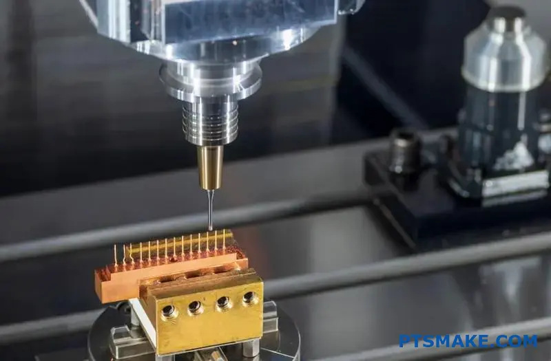
Workholding and Fixturing Challenges in Complex Machining?
Have you ever finalized a complex design, only to discover that holding it for machining is a puzzle in itself? Does the risk of accumulating errors with every new setup undermine your confidence in the final part’s accuracy?
A successful complex CNC machining project depends on a workholding strategy that masters part geometry and minimizes setups. By designing for manufacturability and employing smart fixturing, you can prevent errors, ensure tool accessibility, and hold tight tolerances through every operation.
How Part Geometry Dictates Workholding
The geometry of a part is the first thing we analyze when planning a machining strategy at PTSMAKE. It’s the primary factor that dictates how we’ll hold it. Complex parts rarely have large, flat, parallel surfaces perfect for a standard vise. Instead, we often deal with thin walls, organic curves, and deep pockets, each presenting a unique challenge.
The Problem with Thin Walls and Irregular Shapes
Thin-walled components are highly susceptible to distortion. Too much clamping pressure can easily deform the material, leading to out-of-spec features. Similarly, parts with complex, non-prismatic shapes lack stable surfaces for secure clamping. This forces us to get creative. In these situations, the fixture becomes as critical as the cutting tool. The goal is to provide maximum rigidity with minimum clamping force, distributing pressure evenly to avoid any damage to the part. This is a core challenge in complex CNC machining, where precision is everything.
Designing for Manufacturability: A Proactive Approach
The best way to solve a fixturing problem is to prevent it during the design phase. We often collaborate with clients to incorporate features that simplify workholding. This doesn’t mean compromising the design’s function; it means adding small, strategic elements. This might include adding sacrificial tabs or bosses that provide a secure clamping surface, which are then machined off in a final operation. Another critical aspect is defining a clear datum reference5 system on the drawing. This gives the machinist a stable and repeatable foundation for all measurements and operations, which is non-negotiable when precision is paramount.
| Part Geometry | Common Challenge | Recommended Workholding Solution |
|---|---|---|
| Thin-Walled Components | Distortion under clamping pressure | Low-pressure hydraulic vise, vacuum chuck, custom soft jaws |
| Complex, Organic Shapes | Lack of parallel clamping surfaces | Custom 3D-printed fixtures, dovetail workholding, encapsulation |
| Parts with Deep Pockets | Tool access and chip evacuation | Tall soft jaws, window fixtures, high-pressure coolant systems |
The Hidden Costs of Multiple Setups
Every time a part is removed from a fixture and re-clamped for a new operation, you introduce a potential for error. This is one of the most significant risks in complex CNC machining. Even with the most advanced equipment, it’s impossible to relocate a part with perfect, zero-error repeatability. These tiny inaccuracies accumulate with each setup, a phenomenon known as tolerance stack-up. For a part requiring tight tolerances, just two or three setups can be enough to push a critical dimension out of spec.
Beyond accuracy, multiple setups are a drain on efficiency. Each setup requires the machine to be stopped, the part to be manually handled, and new alignments to be verified. This is non-productive time that increases lead times and drives up costs—two major pain points for any procurement manager.
Strategies to Minimize Setups
The most effective strategy for combating these issues is to machine as many features as possible in a single clamping.
Embrace 5-Axis Machining
This is where 5-axis machining becomes a game-changer. By allowing the cutting tool to approach the workpiece from five different sides without re-clamping, we can complete highly complex parts in one or two setups. At PTSMAKE, our investment in 5-axis technology is central to our ability to deliver high-precision parts with competitive lead times. It directly addresses the problem of tolerance stack-up and improves overall efficiency.
Use Modular Fixturing and Pallet Systems
For production runs, modular fixtures on a pallet system are incredibly effective. We build the fixture and mount the raw material onto a pallet offline while the machine is busy cutting another part. When the machine is ready, the entire pallet is quickly and accurately loaded. This system ensures high repeatability between parts and dramatically reduces machine downtime, turning what could be a 30-minute setup into a one-minute swap.
In complex CNC machining, your workholding strategy is foundational to success. Part geometry directly influences fixture design, while multiple setups introduce risks to both accuracy and efficiency. By proactively designing parts with clamping in mind, leveraging 5-axis technology to minimize setups, and using smart fixturing like modular systems, we can overcome these challenges. This approach ensures that even the most intricate components are machined to spec, on time, and without costly errors.
Surface Finish and Tolerance Strategies for Complex Parts?
Have you ever specified the tightest tolerances and a mirror finish on every feature, only to receive a quote that was far beyond your budget? This is a common pitfall.
For complex parts, effective strategy involves balancing function with manufacturability. You should apply tight tolerances and fine surface finishes only to critical functional surfaces. This selective approach avoids unnecessary costs and extended machining time by minimizing extra manufacturing steps.
The Critical Link Between Design Specs and Cost
In complex CNC machining, surface finish and tolerance are not just numbers on a drawing; they are direct cost drivers. The more complex the part geometry, the more challenging it becomes to achieve a fine finish and hold tight tolerances across all features. For instance, machining a deep, narrow pocket to a very smooth finish is significantly harder than finishing a simple flat surface. The tool has limited access, chip evacuation is difficult, and vibration can become an issue. This is where a strategic approach becomes essential.
Why Over-Tolerancing Is a Budget Killer
One of the most common issues I see is "over-tolerancing"—specifying tolerances tighter than what the part’s function actually requires. Engineers often default to tight tolerances to be safe, but this caution comes at a high price. Each level of precision demands more advanced machinery, specialized tooling, slower cutting speeds, and more frequent inspections. In some of our past projects at PTSMAKE, relaxing a non-critical tolerance from ±0.01mm to ±0.05mm has reduced the machining cost for that feature by over 50%. It’s a simple change that has a huge impact. The key is to ask, "Is this tolerance truly necessary for the part to function correctly?" Proper metrology6 is vital, but it should be applied where it adds value.
Here’s a simplified breakdown of how tolerance can impact cost:
| Tolerance (mm) | Relative Machining Cost | Typical Process |
|---|---|---|
| ±0.1 | 1x | Standard CNC Milling/Turning |
| ±0.025 | 2.5x | Fine CNC Milling/Turning |
| ±0.01 | 5x | Grinding / Precision CNC |
| ±0.005 | 10x+ | Lapping / Honing |
As you can see, tightening the tolerance from a standard ±0.1mm to a precision ±0.01mm can increase the cost fivefold. Always apply the "as loose as possible, as tight as necessary" rule.
How Surface Finish Requirements Shape the Manufacturing Plan
Surface finish, often specified as a Roughness Average (Ra), directly dictates the manufacturing processes required. A standard machined finish might be acceptable for internal components, but a consumer-facing part may need a much smoother, aesthetically pleasing surface. Achieving that finer finish isn’t a simple adjustment; it often requires a completely different manufacturing sequence.
From Primary Machining to Post-Processing
A part’s journey doesn’t always end when it comes off the CNC machine. The required surface finish often determines what happens next. A lower Ra value (smoother finish) typically requires slower feed rates, finer cutting tools, and multiple finishing passes during the CNC process. However, for very fine finishes, secondary operations are unavoidable.
For example, a request for an Ra of 1.6 µm might be achievable with careful CNC milling. But if the drawing calls for an Ra of 0.4 µm, the plan must include post-processing steps like grinding or polishing. Each additional step adds time and cost to the project. We recently worked on a project involving a complex manifold for a fluid dynamics system. The internal channels required a very smooth finish to ensure laminar flow, while the external non-functional surfaces were fine with a standard as-machined finish. By specifying different finishes for different features, the client saved considerable costs without compromising performance.
Here’s how surface finish requirements can influence the choice of process:
| Surface Finish (Ra µm) | Common Processes Required | Use Case Example |
|---|---|---|
| 3.2 – 6.3 | Standard CNC Machining | Internal structural components |
| 1.6 – 3.2 | Fine CNC Machining | Mating surfaces, some visible parts |
| 0.8 – 1.6 | Grinding, Bead Blasting | High-precision fits, good aesthetics |
| < 0.4 | Lapping, Polishing, Honing | Optical components, bearing surfaces |
Understanding this relationship helps you design parts that are both functional and cost-effective to produce. By communicating with your manufacturing partner, like us at PTSMAKE, early in the design phase, you can align your requirements with the most efficient production methods for complex CNC machining.
In complex CNC machining, a thoughtful strategy for surface finish and tolerance is crucial for managing costs and timelines. Remember to apply tight specifications only to critical features where function demands it. This selective approach prevents over-processing non-essential surfaces, which directly translates into savings. Understanding that specific finish requirements dictate additional steps, like grinding or polishing, allows you to create designs that are not just functional but also optimized for manufacturing efficiency and cost-effectiveness.
Material Selection Impact on Complex CNC Machining?
Have you ever finalized a design with a high-performance material, only to discover it doubles the machining cost and lead time? This mismatch can quickly derail even the best-laid project plans.
Material properties like hardness, machinability, and thermal expansion directly influence the feasibility, cost, and time required for complex CNC machining. Selecting a material that balances performance with manufacturability is crucial for achieving your design intent without breaking the budget or timeline.
The Core Properties Influencing Machining Outcomes
When tackling a complex CNC machining project, the material isn’t just a passive element; it’s an active participant that dictates the entire process. Three properties, in particular, have an outsized impact on success, cost, and speed. Understanding them is the first step toward making smarter design and manufacturing decisions.
Hardness and Its Ripple Effect
Material hardness is often the first thing engineers consider for performance, but it has a direct, inverse relationship with machining efficiency. The harder the material (like D2 tool steel or Inconel), the more resistance it puts up against the cutting tool. This translates to:
- Increased Tool Wear: Tools dull faster, requiring more frequent changes and driving up tooling costs.
- Slower Speeds and Feeds: To avoid breaking tools and generating excessive heat, we must run the machines slower, which directly increases cycle time per part.
- Higher Cutting Forces: This can introduce vibration and deflection, making it harder to hold tight tolerances on delicate or complex features.
For intricate parts with fine details, these challenges are magnified. A small end mill cutting hardened steel is a recipe for a slow, costly process with a high risk of tool breakage.
Machinability Ratings as a Guide
Machinability isn’t solely about hardness. It’s a broader measure of how easily a material can be cut, and it accounts for factors like chip formation. For instance, some softer materials like 304 stainless steel are considered "gummy." They produce long, stringy chips that can wrap around the tool and workpiece, potentially ruining the surface finish or breaking the cutter. A formal machinability rating, often benchmarked against 1212 steel, provides a good starting point for comparison.
| Material | Machinability Rating (Approx.) | Key Characteristics |
|---|---|---|
| Aluminum 6061-T6 | 90% | Excellent machinability, good chip control |
| Stainless Steel 304 | 45% | Gummy, requires specific tooling/coolant |
| PEEK | 60% | Good, but sensitive to heat buildup |
| Inconel 718 | 12% | Extremely tough, work hardens rapidly |
The Challenge of Thermal Expansion
Heat is an unavoidable byproduct of machining. As the tool cuts material, friction generates heat that transfers into the workpiece. This causes the material to expand. The issue arises when dealing with tight tolerances, as a material with a high coefficient of thermal expansion7 can move significantly. The part might be perfectly in spec while it’s warm on the machine, but once it cools to room temperature, it can shrink out of tolerance. This is especially problematic for plastics like Delrin and metals like aluminum. Managing this requires advanced strategies like flood coolant, peck drilling cycles, and sometimes even post-machining stress relief, all of which add time and complexity to the process.
A Strategic Approach to Material Selection
Choosing the right material isn’t about always picking the easiest one to machine. It’s about finding the sweet spot where performance requirements and manufacturability intersect. Over-specifying a material can be just as detrimental as under-specifying it. The key is to make a conscious, informed trade-off.
Balancing Performance, Cost, and Volume
In our work at PTSMAKE, we often guide clients through a decision-making process that weighs application needs against manufacturing reality. It helps to think about it in terms of a simple matrix. Ask yourself which factors are non-negotiable and which have some flexibility.
| Priority | Example Considerations | Material Leanings |
|---|---|---|
| Performance-Driven | Must withstand extreme heat or corrosive chemicals. Requires highest possible strength. | Inconel, Titanium, PEEK, Hardened Steels. Be prepared for higher machining costs. |
| Cost-Driven | A functional prototype or a part for a non-critical application. | Aluminum 6061, Brass, Delrin (Acetal). These materials offer great value and easy machining. |
| Balanced Approach | Needs good corrosion resistance and strength, but cost is also a factor. | Stainless Steel 303 (more machinable than 304), Aluminum 7075. Good middle-ground options. |
By categorizing your project’s primary driver, you can narrow down material choices and have a more productive conversation with your manufacturing partner. Sometimes, a slight design modification can allow for a more machinable material, saving significant costs without compromising function.
When to Consider Alternatives: Electrical Discharge Machining (EDM)
Sometimes, the combination of material and geometry makes conventional CNC machining impractical. This is especially true for features that are impossible for a rotating tool to create. That’s when it’s time to look at alternative processes.
For complex CNC machining challenges, Electrical Discharge Machining (EDM) is a powerful tool in our arsenal. EDM uses controlled electrical sparks to erode material, offering unique advantages:
- Machining Ultra-Hard Materials: It can cut any conductive material, regardless of its hardness. This makes it ideal for hardened tool steels, titanium, and exotic alloys that are brutal on conventional cutting tools.
- Creating Sharp Internal Corners: A milling tool is round, so it will always leave a radius in an internal corner. EDM can produce perfectly sharp, square internal corners.
- Stress-Free Machining: Because the electrode never physically touches the workpiece, there are no cutting forces. This allows for the creation of extremely thin walls and delicate features that would warp or break under the pressure of milling.
Recognizing the limits of one process and knowing when to apply another is a hallmark of a true manufacturing partner. For certain complex features, forcing a solution with CNC is less efficient and more expensive than switching to a more suitable method like EDM.
Material selection is a foundational decision in complex CNC machining that dictates cost, lead time, and overall feasibility. Key properties like hardness, machinability, and thermal expansion present unique challenges that must be managed. A strategic balance between a material’s performance and its ease of machining is essential for success. For designs with extremely hard materials or features impossible to mill, alternative processes like EDM provide a more effective and often more economical manufacturing path.
Cost-Effective Approaches to Complex CNC Machined Parts.
Struggling to keep your complex CNC machining costs from escalating? Do you find that achieving high precision often means sacrificing your budget, forcing difficult trade-offs in your design?
The key to cost-effective complex CNC machining lies in intelligent Design for Manufacturing (DFM). By consolidating features, standardizing dimensions, and minimizing tight tolerances, you can significantly reduce programming, setup, and machining time, directly lowering your per-unit cost without compromising essential functionality.
Strategic Design for Manufacturing (DFM)
One of the most impactful areas to control costs is during the design phase, long before a block of metal ever reaches the machine. In our experience at PTSMAKE, a few fundamental DFM principles consistently deliver the most significant savings for complex parts.
Feature Consolidation
Instead of designing an assembly of multiple simple parts that need to be fastened together, consider if they can be combined into a single, more complex machined component. While the individual part may seem more intricate, this approach eliminates the costs associated with producing multiple components, managing a larger bill of materials, and, most importantly, the labor and time required for assembly. It can also improve the overall strength and accuracy of the final product by removing potential points of failure or misalignment between separate parts.
The Power of Standardization
Engineers love creativity, but when it comes to cost, standardization is your best friend. Sticking to standard drill sizes, thread specifications, and tool radii means we can use off-the-shelf tooling. Every time a design requires a custom tool, it adds cost and lead time for tool procurement and unique setup procedures. For example, designing pockets with corner radii that match standard end mill sizes (e.g., 3mm, 6mm, 10mm) is far more efficient than specifying a non-standard 4.75mm radius that would require a custom tool or slower machining process. This seemingly small detail has a big impact on overall cycle time.
Tolerances: The Hidden Cost Driver
Unnecessarily tight tolerances are perhaps the single biggest contributor to inflated costs in complex CNC machining. Every dimension on a drawing should be questioned: "Does it really need to be this precise?" The relationship between tolerance and cost is not linear; it’s exponential. Loosening a non-critical tolerance can dramatically reduce machining time, tooling wear, and inspection requirements. A proper understanding of Geometric Dimensioning and Tolerancing8 helps clearly define which features are critical and which are not.
The table below, based on data from projects we’ve handled, illustrates how tightening tolerances affects machining effort.
| Tolerance Level | Relative Machining Time | Relative Cost Impact |
|---|---|---|
| Standard (±0.1 mm) | 1x | Base |
| Tight (±0.025 mm) | 2.5x | Significant Increase |
| Very Tight (±0.01 mm) | 5x+ | Exponential Increase |
As you can see, simply asking for higher precision where it isn’t functionally required can double or triple your costs.
Balancing Complexity, Volume, and Cost
Making informed decisions during the design phase requires a clear understanding of the trade-offs between three core factors: the complexity of your part, the volume you intend to produce, and the resulting unit cost. These elements are interconnected, and optimizing one often impacts the others.
The Complexity-Cost Relationship
As a part’s complexity increases—through intricate geometries, multiple surfaces, or the need for 5-axis machining—the cost per part naturally rises. This is due to several factors:
- Programming Time: More complex parts require significantly more CAM programming time.
- Setup and Fixturing: Custom fixtures may be needed to hold the part securely and accurately for various operations.
- Machining Time: Intricate features often require slower cutting speeds, smaller tools, and more machine repositioning, all of which extend the cycle time per part.
- Inspection: Verifying complex geometries and tight tolerances requires more advanced inspection equipment (like a CMM) and more time from quality control technicians.
For prototypes and low-volume runs, these upfront costs are spread over very few units, making the per-part cost very high.
How Production Volume Changes the Equation
Economies of scale play a massive role in complex CNC machining. While the initial setup and programming costs are high, they are one-time expenses. As production volume increases, these costs are amortized across a larger number of parts, causing the unit cost to drop significantly.
This table shows a simplified breakdown of how volume impacts cost distribution:
| Production Volume | Setup Cost Impact | Machining Cost Impact | Unit Cost |
|---|---|---|---|
| 1-10 Parts (Prototype) | Very High | High | Very High |
| 100-500 Parts (Low-Vol) | Medium | Medium | Moderate |
| 1000+ Parts (Production) | Low | Optimized | Low |
For high-volume projects, it might even be cost-effective to invest in more advanced fixtures or optimized tooling that reduces the cycle time, a strategy that wouldn’t make sense for a handful of parts.
Making Informed Decisions Early
The best time to balance these factors is at the very beginning of the design process. This is where partnering with a manufacturer like PTSMAKE early on provides immense value. Before finalizing a design, ask critical questions:
- Is every feature on this part functionally necessary?
- Can this tolerance be relaxed without affecting performance or fit?
- Is there a simpler geometry that could achieve the same result?
- How will the expected production volume influence my material and design choices?
By addressing these questions, you can steer your design toward a solution that is not only functional but also optimized for manufacturing efficiency from the start.
In short, achieving cost-effective complex CNC machining is less about cutting corners and more about making smart, informed decisions upfront. By applying DFM principles like consolidating features, using standard dimensions, and critically evaluating every tolerance, you can slash expenses. Understanding the trade-offs between complexity and production volume further empowers you to design parts that are optimized for your budget and performance needs. Early collaboration with your manufacturing partner is crucial for unlocking these significant savings and ensuring project success.
Common Design Mistakes to Avoid in Complex CNC Machining?
Have you ever designed a complex part that looked perfect in CAD, only to face soaring production costs or unexpected delays? The issue often lies in small design details overlooked before manufacturing begins.
The most common mistakes in complex CNC machining involve over-specifying tolerances, designing features that are difficult or impossible to machine, and neglecting tool access. Correcting these early improves manufacturability, reduces costs, and ensures higher quality for the final part.
The High Cost of Unnecessary Precision
One of the most frequent issues we see in projects at PTSMAKE is the over-specification of tolerances. Engineers, aiming for perfection, often apply extremely tight tolerances across an entire part. While precision is the goal of complex CNC machining, not every feature requires the same level of accuracy. Applying a blanket tolerance of ±0.001 inches to non-critical surfaces can dramatically inflate costs without adding any functional value.
Why does this happen? Achieving tighter tolerances requires more careful setups, slower machine speeds, specialized tooling, and more intensive quality control processes. For example, a standard milling operation might be quick and cost-effective, but holding an ultra-tight tolerance could necessitate a final grinding step or multiple inspection rounds using advanced Metrology9 equipment. This extra machine time and labor directly translate to higher costs and longer lead times. The key is to apply tight tolerances only where they are functionally necessary—such as on mating surfaces, bearing bores, or critical alignment features. For all other surfaces, specifying a more standard, looser tolerance will make the part significantly more economical to produce.
Designing Features That Challenge Physics
Another common hurdle is designing features that are theoretically possible in a CAD environment but impractical or impossible to create on a CNC machine. These designs often ignore the physical limitations of cutting tools and machine kinematics.
Unrealistic Sharp Internal Corners
A classic example is designing sharp, 90-degree internal corners. Standard end mills are cylindrical, meaning they will always leave a radius in an internal corner. Creating a perfectly sharp corner is impossible with a standard milling tool. While techniques like EDM (Electrical Discharge Machining) can achieve this, they add a completely separate and expensive process. A much better approach is to design a small radius, or fillet, into all internal corners. The radius should be slightly larger than the radius of the cutting tool you intend to use.
The Trouble with Deep, Narrow Pockets
Deep, narrow pockets or channels also present a major challenge. Machining these features requires a long, thin cutting tool. Such tools are prone to deflection, vibration (chatter), and breakage, all of which compromise surface finish and dimensional accuracy. As a rule of thumb, the depth of a pocket should ideally be no more than four to six times the diameter of the cutting tool. If a deep pocket is unavoidable, consider design alternatives like widening the pocket to allow for a more robust tool or designing the part as two separate components that can be assembled later.
| Common Mistake | Why It’s a Problem | Manufacturable Alternative |
|---|---|---|
| Blanket Tight Tolerances | Increases machine time, tooling wear, and inspection costs. | Apply tight tolerances only to critical features. |
| Sharp Internal Corners | Standard tools are round; requires a secondary, expensive process. | Design a small radius (fillet) in all internal corners. |
| Deep, Narrow Pockets | Tool deflection and vibration lead to poor finish and inaccuracy. | Widen the pocket or reduce its depth-to-diameter ratio. |
Forgetting the Tool Needs to Get There
A beautifully designed feature is useless if the cutting tool cannot physically reach it to machine it. Tool access is a fundamental aspect of Design for Manufacturability (DFM) that is surprisingly easy to overlook, especially in parts with complex geometries. Every surface that needs to be machined must have a clear, unobstructed path for the cutting tool and its holder.
Hidden Features and Troublesome Undercuts
Features located in deep cavities or blocked by other walls can be impossible to machine with standard 3-axis or even 5-axis setups. An undercut, a feature that cannot be machined from the top down, is a common example. While special tooling like lollipop or T-slot cutters can create some undercuts, they have limitations and add significant complexity and cost. In many past projects, we’ve found it’s more effective to redesign the part to eliminate the undercut. This might involve splitting a single, complex component into two simpler parts that are later fastened together. This approach not only solves the access issue but often simplifies the entire manufacturing process.
The Dangers of Thin Walls and Cluttered Features
Another access-related issue is designing walls that are too thin. Thin walls lack rigidity and can vibrate or deflect under the pressure of the cutting tool, leading to dimensional inaccuracies and a poor surface finish. In some cases, they can even break during machining. We typically recommend a minimum wall thickness based on the material and overall part size, but a good starting point is to avoid walls thinner than 0.8mm (0.03 inches) for metals. Similarly, placing features too close to each other can prevent a tool from fitting between them. Always leave adequate clearance around features to accommodate the diameter of the cutting tool and its holder. Thinking about the tool’s path during the design phase is crucial for successful complex CNC machining outcomes.
| Access Problem | Machining Challenge | Design Solution |
|---|---|---|
| Obstructed Features | The tool cannot reach the surface to cut it. | Ensure a clear path for the tool; simplify geometry. |
| Undercuts | Requires special, costly tooling and complex machine paths. | Redesign to eliminate the undercut or split the part. |
| Thin Walls | Vibration, deflection, and potential breakage during machining. | Increase wall thickness for rigidity. |
| Crowded Features | Not enough space for the tool to fit between features. | Increase the spacing between adjacent features. |
Avoiding common design mistakes is crucial for efficient complex CNC machining. By specifying tolerances only where necessary, you can significantly reduce costs. Designing manufacturable features, such as adding radii to internal corners and avoiding deep, narrow pockets, prevents production delays. Most importantly, always considering tool access ensures your design can be physically created. Thinking about the manufacturing process from the start leads to better, more cost-effective parts and a smoother production experience.
Design Guidelines for Engineers: Ensuring Manufacturability and Performance.
Ever finalized a complex part design, only to be hit with an unexpectedly high manufacturing quote or a report that it’s unmachinable? This gap between design and reality causes frustrating delays and budget overruns.
To ensure manufacturability and performance for complex CNC machining, engineers must integrate Design for Manufacturability (DFM) principles, collaborate with suppliers early, and use simulation and prototyping to validate designs before committing to full-scale production.
Core DFM Principles for Complex Parts
Design for Manufacturability (DFM) is the practice of designing products in a way that makes them easy and cost-effective to manufacture. For complex CNC machining, this doesn’t mean simplifying your design to the point of compromising its function. Instead, it means making intelligent choices that respect the realities of the machining process. It’s about working with the process, not against it. In past projects at PTSMAKE, we’ve seen how small DFM adjustments can lead to significant cost and time savings without altering the part’s core performance.
Mindful Tolerancing
Not every surface needs a razor-sharp tolerance. Over-tolerancing is one of the most common drivers of unnecessary cost. Tighter tolerances require more precise machine setups, slower cutting speeds, more frequent tool changes, and extensive quality inspection. The key is to apply tight tolerances only where they are functionally critical. For non-critical features, using standard tolerances can drastically reduce machining time and cost. We’ve found that relaxing a tolerance from ±0.01mm to ±0.05mm on a non-mating surface can sometimes cut the cost for that specific feature in half.
Tool Access and Radii
Think about how a cutting tool will physically access the material it needs to remove. Deep pockets with small inside corners are a classic challenge. Standard end mills are round, so they will always leave a radius in an internal corner. Specifying a perfectly sharp 90-degree internal corner is impossible without secondary processes like EDM. Instead, design internal corners with a radius that is slightly larger than the cutting tool’s radius. A good rule of thumb is to make the corner radius at least 1/8th of the cavity depth. This allows for a more rigid, shorter tool, which reduces chatter and improves surface finish. Geometric Dimensioning and Tolerancing10 is the language used to define these features precisely.
Wall Thickness and Feature Ratios
For parts requiring extensive material removal, thin walls can be problematic. They are prone to vibration (chatter) during machining, which can lead to poor surface finish and dimensional inaccuracies. They can also warp from the stresses induced during the process.
| Feature | Recommended Guideline | Reason |
|---|---|---|
| Minimum Wall Thickness | > 0.8mm for metals, > 1.5mm for plastics | Prevents vibration, warping, and tool breakage. |
| Hole Depth-to-Diameter Ratio | < 10:1 | Deeper holes cause issues with chip evacuation and coolant flow. |
| Aspect Ratio (Height:Width) of Features | < 4:1 | Tall, thin features are unstable and difficult to machine accurately. |
Following these guidelines creates a more robust part that can withstand the forces of complex CNC machining.
The Value of Collaboration and Validation
A great design on paper is only half the battle. Bringing that design to life efficiently requires teamwork and verification. The most successful projects I’ve worked on involved a strong partnership between the design engineer and the manufacturing team right from the start. This collaborative approach uncovers potential issues long before they become expensive problems on the shop floor. It transforms the manufacturing process from a simple service into a strategic advantage.
Early Supplier Involvement (ESI)
Don’t wait until your design is "final" to talk to your manufacturing partner. Engaging a supplier like PTSMAKE during the conceptual phase provides access to a wealth of practical experience. We can review your initial designs and offer feedback on material selection, tolerancing strategies, and feature geometry that could improve manufacturability. For example, a client once brought us a design for an aluminum housing that required deep-pocket milling. By suggesting a minor change to the internal corner radii and adding a slight draft angle, we helped them reduce the projected machining time by over 30%, a saving that went straight to their bottom line. This early dialogue is crucial for optimizing parts intended for complex CNC machining.
Prototyping for Physical Verification
Simulation is powerful, but nothing beats holding a physical part in your hands. Prototyping is an essential validation step. It allows you to:
- Test Form and Fit: Check how your part interacts with other components in an assembly.
- Validate Material Choice: Ensure the selected material meets the functional requirements for strength, weight, and durability.
- Perform Functional Testing: Subject the part to real-world conditions to verify its performance before investing in production tooling.
We often recommend a multi-stage prototyping process. Start with a low-cost 3D-printed model for initial form and fit checks, then move to a CNC-machined functional prototype using the final production material. This iterative approach de-risks the entire project.
Using Simulation to Predict Outcomes
Before any material is cut, simulation software can provide incredible insights. Finite Element Analysis (FEA) can predict how a part will react to stress, vibration, and thermal loads, helping you optimize the design for strength while minimizing weight. Computer-Aided Manufacturing (CAM) simulation shows the exact toolpaths the CNC machine will follow. We use this internally to identify potential tool collisions, estimate cycle times, and ensure the machine can create every feature as designed. For engineers, providing your manufacturer with your own FEA results can also accelerate the DFM feedback process.
Mastering design for complex CNC machining hinges on a practical, forward-thinking approach. It’s about making smart choices based on DFM principles, such as mindful tolerancing and tool-friendly geometry. More importantly, it involves transforming the manufacturing relationship into a partnership through early supplier collaboration. By validating your designs with simulations and physical prototypes, you bridge the critical gap between concept and a high-performance, cost-effective final product, ensuring your vision becomes a manufacturable reality.
Unlock Complex CNC Machining Success with PTSMAKE Expertise
Ready to master complex CNC machining and optimize your next project? Send your RFQ to PTSMAKE today and experience precision, efficiency, and expert support from prototype to production. Our specialists help reduce costs and deliver exceptional results for your toughest manufacturing challenges—let’s get started!

Click to understand how a machine’s axes directly impact the complexity and cost of your part’s design. ↩
Learn how choosing the right datum reference can dramatically simplify your machining process and improve final part accuracy. ↩
Learn about the physics behind this harmful tool vibration and how to mitigate it in your designs. ↩
Learn how this engineering principle affects part durability and how to design against it. ↩
Understand how defining and using datums correctly ensures part accuracy across all manufacturing operations. ↩
Learn more about the science of measurement and how it ensures your parts meet exact specifications. ↩
Understand how this crucial property affects precision and explore strategies to manage it in your designs. ↩
Learn to use this symbolic language on engineering drawings to precisely communicate functional requirements and reduce manufacturing ambiguity. ↩
Explore the principles of metrology to better understand how tolerances are measured and verified in precision manufacturing. ↩
Explore GD&T to learn how to precisely define and communicate functional design intent on your engineering drawings. ↩