Finding the right die casting manufacturer feels like navigating a maze of technical claims and marketing promises. You need precision parts that meet strict tolerances, but how do you separate truly capable manufacturers from those who just talk a good game?
A reliable die casting manufacturer combines advanced equipment, proven alloy expertise, rigorous quality control, and comprehensive project management from initial RFQ through full production. The best partners demonstrate their capabilities through documented processes, consistent results, and transparent communication throughout every project phase.
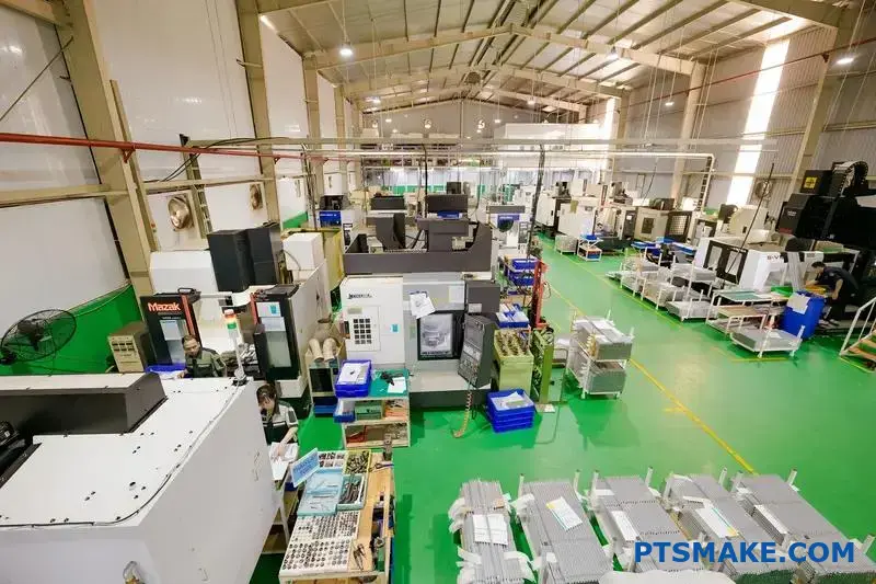
I’ve worked with manufacturers across the spectrum at PTSMAKE, and I’ve seen the real difference between good intentions and actual delivery. The questions I’ll walk you through below come directly from situations where the right knowledge made the difference between project success and costly delays.
What defines a high-quality die cast part practically?
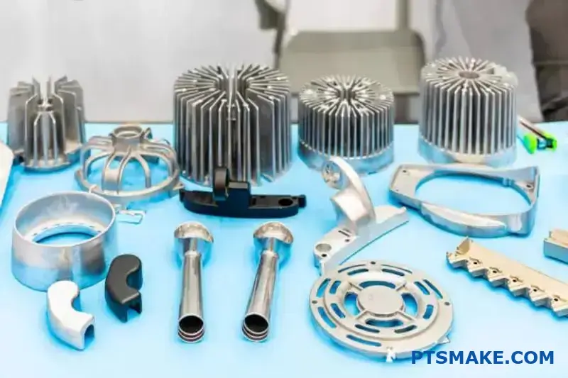
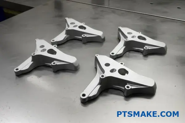
Let’s move beyond textbook definitions. A high-quality die cast part is one that performs its function flawlessly in the final product. It is as simple as that.
This practical quality is not just a single feature. It is a combination of several critical metrics. Each one plays a vital role.
Key Practical Metrics
How well a part performs depends on these core factors. They are the true measure of quality.
| Metric | Practical Impact on Function |
|---|---|
| Dimensional Accuracy | Guarantees parts fit together perfectly. |
| Surface Finish | Affects appearance and coating adhesion. |
| Mechanical Properties | Determines durability and load-bearing capacity. |
| Absence of Defects | Prevents unexpected and premature failure. |
A high-quality part is more than hitting numbers on a spec sheet. It’s about achieving consistency across a full production run. This ensures every single component performs reliably.
The Reality of Tolerances
Tight tolerances are often requested. But in our experience, the first question should be why. Is it for fit, function, or aesthetics?
Understanding the end-use allows us to optimize the manufacturing process. This collaborative approach helps avoid unnecessary costs for our clients. It ensures the specification is practical and purposeful.
Material Integrity is Non-Negotiable
Mechanical properties like strength are forged during the casting itself. The injection speed of the molten metal and the subsequent cooling rate are critical variables.
This control over the cooling process is vital. It directly impacts the material’s dendritic1 arm spacing. This, in turn, defines its final strength and ductility.
An experienced die casting manufacturer knows how to manage these variables. This ensures the final part withstands real-world stress without failing. At PTSMAKE, we use simulation software to predict and optimize these outcomes before production begins.
A high-quality die cast part’s value is proven in its performance. It’s defined by precise dimensions, a flawless finish, and robust mechanical properties that ensure it functions perfectly and reliably in the final product assembly, not just on a quality report.
What are the essential properties of die casting alloys?
Choosing the right die casting alloy is crucial. It goes beyond just the initial cost. The alloy’s properties directly impact the part’s performance and manufacturability.
Key Material Properties
We focus on four essential properties. These are melting point, fluidity, strength-to-weight ratio, and corrosion resistance. Each one plays a vital role.
Understanding these dictates the alloy’s final application.
| Property | Importance in Die Casting |
|---|---|
| Melting Point | Affects energy cost and mold life |
| Fluidity | Determines ability to fill complex mold cavities |
| Strength-to-Weight | Crucial for lightweight, strong parts |
This balance ensures the final component meets design specifications perfectly.
Why These Properties Matter
The choice of alloy is a strategic decision. A low melting point, found in zinc alloys, means lower energy costs. It also extends the life of the steel molds, a significant factor in production budgeting.
High fluidity is another key factor. It allows molten metal to fill thin walls and intricate details. Zinc and magnesium alloys excel here. This reduces the risk of defects.
Balancing Strength and Weight
The strength-to-weight ratio is critical. This is especially true in automotive and aerospace. Magnesium alloys are champions here, offering great strength while being incredibly light. Aluminum is a popular all-rounder. It offers a great balance of strength, weight, and cost. The narrow solidification range2 of certain aluminum alloys is also a key benefit.
| Alloy | Key Benefit | Common Application |
|---|---|---|
| Zinc | High fluidity, low melting point | Intricate decorative parts, electronics |
| Aluminum | Balanced properties, cost-effective | Automotive components, consumer goods |
| Magnesium | Highest strength-to-weight ratio | Aerospace parts, power tools |
Resistance to the Elements
Corrosion resistance is vital for parts in harsh environments. Certain alloys naturally resist rust. This can eliminate the need for secondary finishing, like painting. As a die casting manufacturer, we help clients navigate these trade-offs to find the optimal solution.
Selecting the right alloy is a balancing act. Properties like melting point, fluidity, and strength-to-weight ratio directly influence the final part’s performance, durability, and overall production cost. This decision is fundamental to successful die casting.
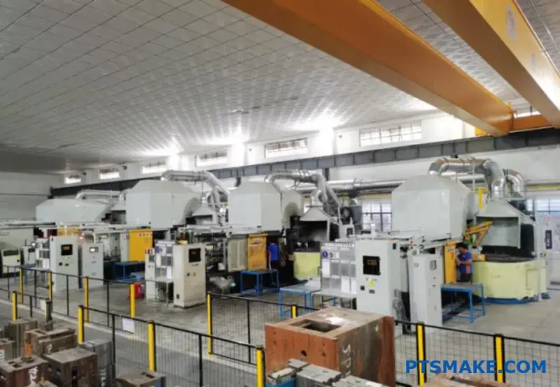
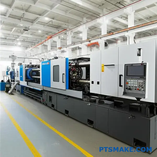
What is the basic die casting production cycle?
The die casting cycle is a rapid, precise sequence. Each step is critical for the final part’s quality. Think of it as a carefully choreographed dance. This dance is repeated thousands of times a day. Let’s break down the six core stages.
The Practitioner’s View
This cycle is the heartbeat of production. Understanding it helps in optimizing for better results.
Stage Breakdown
The entire process is incredibly fast. A complete cycle often lasts only a few seconds. This speed makes die casting ideal for high-volume production.
| Stage | Key Action |
|---|---|
| Mold Closing | Secures the two die halves under pressure. |
| Injection | Fills the mold cavity with molten metal. |
| Cooling | Allows the metal to solidify into the part’s shape. |
| Mold Opening | Separates the die halves to reveal the part. |
| Ejection | Pushes the solidified casting out of the mold. |
| Spraying | Prepares the mold surface for the next cycle. |
Knowing these steps is the first step toward optimization.
Knowing the steps is one thing. Mastering them is another. A skilled die casting manufacturer fine-tunes each phase for optimal results. This detailed control separates acceptable parts from exceptional ones. At PTSMAKE, this is where our experience makes a difference.
The "Why" Behind Each Step
Injection and Cooling Nuances
Injection speed and pressure are critical. They determine the metal flow, surface finish, and internal density. It’s a delicate balance to avoid defects like porosity.
The cooling stage is where the part’s final strength is set. As the metal solidifies, its internal grain structure forms. How it cools affects everything. Issues like solute segregation3 can arise if the process is not carefully controlled, potentially weakening the component.
Ejection and Mold Preparation
Ejecting the part without causing damage requires precision. The casting is still hot and relatively soft. Even pressure from ejector pins is essential to prevent warping or marks.
Finally, mold spraying is not just for lubrication. It also helps regulate the die’s temperature. A consistent die temperature is key to producing consistent parts, cycle after cycle.
| Stage | Critical Purpose | Potential Issue if Done Poorly |
|---|---|---|
| Cooling | Determine final mechanical properties. | Internal stress or cracks. |
| Ejection | Remove the part without damage. | Part deformation or surface blemishes. |
| Spraying | Lubricate and control die temperature. | Sticking, or inconsistent part quality. |
This is where a partnership with an experienced manufacturer truly pays off.
This six-step process is the core of die casting production. Every stage, from clamping the mold to spraying the die, directly impacts the quality, finish, and dimensional accuracy of the final component. Mastering this cycle is essential for consistency.
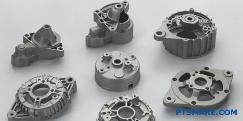
What types of secondary operations are commonly required?
After a part leaves the die casting machine, its journey is not over. It enters the post-casting workflow. This stage is crucial for meeting final design specifications.
These secondary operations refine the raw casting. They transform it into a precise, finished component. We can group them into several key stages.
| Operation Category | Purpose |
|---|---|
| Material Removal | To remove excess material and refine shape. |
| Machining | To achieve tight tolerances and specific features. |
| Surface Finishing | To improve appearance and environmental protection. |
Secondary operations are where a raw part becomes a finished product. Each step adds value and precision, ensuring the component functions as intended. A skilled die casting manufacturer integrates these steps seamlessly into their process.
Material Removal Processes
The first step is typically trimming. This process removes excess material from the casting. This includes gates, runners, and overflow flash.
Next comes deburring. This operation removes sharp edges or small imperfections left from the casting and trimming processes. It’s vital for part safety and proper assembly fit.
Precision Machining
Die casting alone may not achieve the tightest tolerances. This is where CNC machining becomes essential.
At PTSMAKE, we use machining to create features that are impossible to cast directly. This includes threading holes, creating flat mating surfaces, or boring precise diameters. It ensures the part meets exact engineering requirements.
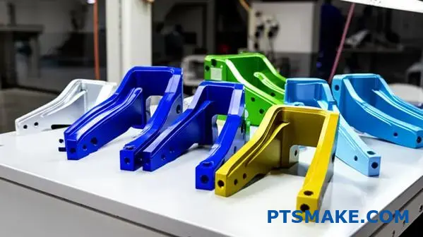
Surface Finishing Treatments
Finishing is the final stage. It enhances both the look and durability of the part. The chosen finish depends entirely on the part’s final application.
Common treatments include painting or powder coating. Plating with nickel or chrome adds wear resistance. Anodizing4 is an electrochemical process specifically for aluminum parts.
| Finishing Type | Primary Benefit | Common Application |
|---|---|---|
| Painting/Powder Coating | Aesthetics, Moderate Protection | Housings, Brackets |
| Plating (Chrome, Nickel) | Durability, Corrosion Resistance | Automotive Trim, Fixtures |
| Anodizing | Hardness, Corrosion Resistance | Electronic Enclosures, Consumer Goods |
These secondary operations are not optional extras. They are integral to manufacturing. They ensure the final part meets all functional, aesthetic, and performance requirements from the initial design.
How are common casting defects categorized?
To solve a problem, you first need to organize it. I find it helpful to create a mental library of casting defects. This turns a complex issue into a structured map.
We group defects into three main categories. This simple structure is key for effective troubleshooting.
Surface Defects
These are flaws you can see on the casting’s exterior. Think of flow lines or surface roughness.
Internal Defects
These are hidden inside the part. They often require inspection methods like X-ray to find.
Dimensional Defects
These happen when the final part does not match the design specifications.
Here is a quick breakdown:
| Defect Category | Common Examples |
|---|---|
| Surface Defects | Flow lines, cracks, blisters |
| Internal Defects | Porosity, shrinkage, inclusions |
| Dimensional Defects | Warping, mismatch, incorrect size |
Categorizing defects isn’t just an academic exercise. It is the first step in practical, efficient problem-solving. Each category points toward a different area of the casting process. This allows us to narrow down the potential root causes quickly.
Troubleshooting Based on Category
A systematic approach saves time and money. It avoids guesswork and focuses on data-driven solutions. As a die casting manufacturer, we rely on this process daily.
Tackling Surface Issues
When we see surface defects, we often look at the mold first. Issues like mold temperature, coating, or injection speed are common culprits. The problem is related to how the metal fills the mold.
Investigating Internal Flaws
Internal defects point to deeper issues. We might investigate the raw material quality or the melting process. Trapped gases can cause porosity5, a common internal flaw. Cooling rates are also a critical factor here.
Correcting Dimensional Errors
If a part’s dimensions are off, the problem is often mechanical or thermal. It could be mold wear, incorrect shrinkage calculations, or machine clamping force. We check the tool and the process parameters.
Organizing casting defects into surface, internal, and dimensional categories is essential. This structured approach simplifies troubleshooting by immediately pointing to potential root causes, turning a complex problem into a manageable process of elimination for faster resolution.
What machine tonnage classifications exist and why?
Choosing the right machine tonnage is crucial. It’s about applying enough clamping force to keep the mold shut during injection. Think of it as a giant vise.
The required force depends directly on the part’s size. A larger part has a greater surface area for the molten plastic to push against.
The Role of Projected Area
The key metric is the "projected area." This is the two-dimensional shadow the part would cast. More area means more separating force from the plastic. This force must be countered by the machine’s clamping force.
| Projected Area | Required Tonnage | Common Application |
|---|---|---|
| Small | 30-100 Tons | Small gears, connectors |
| Medium | 100-500 Tons | Electronic housings, enclosures |
| Large | 500+ Tons | Automotive dashboards, bins |
Insufficient tonnage leads to a critical defect called "flash."
The core relationship is simple: machine tonnage must overcome the injection pressure exerted on the part’s projected area. If the injection pressure wins, the mold halves separate slightly. This allows plastic to escape, creating flash.
However, a simple calculation isn’t enough. Experience tells us other factors are at play. At PTSMAKE, we consider the complete picture for our clients.
Beyond Basic Area Calculations
The type of plastic is a major factor. Materials with a low viscosity6 flow very easily, like water. They require more clamping force to contain, as they can find even the smallest gap.
Conversely, thicker materials require higher injection pressures to fill the mold. This also increases the separating force. It’s a delicate balance. A similar principle applies in metalworking; a quality die casting manufacturer must manage extreme pressures to ensure part integrity.
Factors Influencing Tonnage Needs
| Factor | Required Tonnage | Why? |
|---|---|---|
| Part Complexity | Increases | Intricate designs can create uneven pressure. |
| Wall Thickness | Varies | Thin walls need high pressure; thick walls take longer to cool. |
| Material Type | Varies | Flow characteristics dictate the force needed for containment. |
In our experience, we typically use a safety factor of at least 10%. This ensures the machine isn’t running at its absolute limit, promoting consistency and longevity.
Machine tonnage, or clamping force, must be greater than the injection pressure across the part’s projected area. This fundamental balance prevents defects like flash, ensuring the production of high-quality, precise parts that meet specifications.
What are the different levels of part approval processes (PPAP)?
The Part Approval Process (PPAP) is not just paperwork. It is a structured conversation between the supplier and the customer.
This process ensures that we, as the supplier, understand all customer requirements. It also proves our manufacturing process can consistently produce parts that meet those specifications.
The Five Levels of Submission
PPAP has five distinct levels. Each level dictates the specific evidence we must provide to the customer for approval. The required documentation increases with each level.
| PPAP Level | Submission Requirement |
|---|---|
| Level 1 | Part Submission Warrant (PSW) only. |
| Level 2 | PSW with product samples and limited supporting data. |
| Level 3 | PSW with product samples and complete supporting data. |
| Level 4 | PSW and other requirements as defined by the customer. |
| Level 5 | PSW with product samples and complete supporting data available for review at the supplier’s manufacturing location. |
This tiered system allows for flexibility based on the part’s complexity and the customer’s needs.
PPAP is fundamentally about managing risk and building trust. The level requested by a customer often reflects their perceived risk associated with a new part or a process change.
At PTSMAKE, we guide our clients through this selection. A simple, low-risk component might only need a Level 1 submission.
Aligning on Expectations
However, a critical component for the automotive or aerospace industry will almost certainly require a full Level 3 submission. This includes everything from the design records to the final sample part data.
For instance, as a die casting manufacturer7, we often provide Level 3 documentation. This includes a detailed process flow diagram, failure mode and effects analysis (FMEA), and a comprehensive control plan.
This deep dive ensures there are no surprises once production starts.
When are Different Levels Used?
Deciding on the right level is a collaborative effort. It depends on factors like part criticality, past supplier performance, and any changes to the design or process. We have found clear communication at this stage prevents future delays.
| Level | Typical Use Case | Documentation Scope |
|---|---|---|
| Level 1 | Minor changes, low-risk parts. | Minimal (PSW only) |
| Level 3 | New parts, standard submission. | Comprehensive |
| Level 5 | On-site review needed. | Full documentation at our facility |
Ultimately, the goal is to provide the right amount of evidence to give the customer complete confidence in our manufacturing process. This proactive alignment is key to a smooth launch.
PPAP establishes clear, structured communication. Its five levels define the required documentation, ensuring a supplier’s process consistently meets customer specifications and manages risk effectively before full-scale production begins.
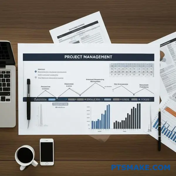
How would you manage a project from RFQ to first production?
A solid project plan is your roadmap. It turns an idea into a physical product. Without it, you’re just guessing.
This plan has clear stages. Each stage has a specific goal. This ensures everyone is on the same page from start to finish.
Key Project Milestones
Here’s a simple breakdown of the major milestones. We follow this path for every project to ensure a smooth journey from RFQ to production.
| Milestone | Key Objective |
|---|---|
| Quoting | Provide an accurate and transparent cost estimate. |
| DFM Review | Optimize the part design for manufacturing. |
| Die Build | Monitor and manage the tool creation process. |
| Sampling | Produce first parts for evaluation and testing. |
| PPAP | Validate that the process can meet all specs. |
| Launch | Begin full-scale mass production. |
This structured approach removes surprises.
A Deeper Look at Each Milestone
Let’s break down each stage further. Success depends on mastering the details at every step. This journey requires precision and clear communication.
Quoting and DFM
The quoting stage is more than a price. It’s our first chance to understand your project’s needs. We review your CAD files and specifications carefully.
After quoting, we move to the Design for Manufacturability (DFM) review. This is a critical collaborative step. Our engineers work with your team to identify potential issues. The goal is to optimize the design before any metal is cut.
Die Build and Sampling
Once the design is locked, we start building the die. We provide a detailed schedule, often using a Gantt chart. This allows you to track progress transparently. Working with an experienced die casting manufacturer is key here.
First shots, or T1 samples, are a major milestone. We send these initial parts to you for inspection. This is your first look at the physical product from the new tool. Your feedback is crucial for any final adjustments.
PPAP and Production Launch
The Production Part Approval Process (PPAP) is the final quality gate. It’s a comprehensive report. It proves our process can consistently produce parts that meet your requirements. This includes checks like a Gage R&R8 study.
With PPAP approval, we get the green light. The project officially moves from development to mass production, ready to meet your volume needs.
A structured plan with clear milestones is essential. It guides the project from the initial quote through DFM, tool building, sampling, and PPAP, ensuring a successful and predictable launch into mass production. This framework minimizes risks and aligns all teams.
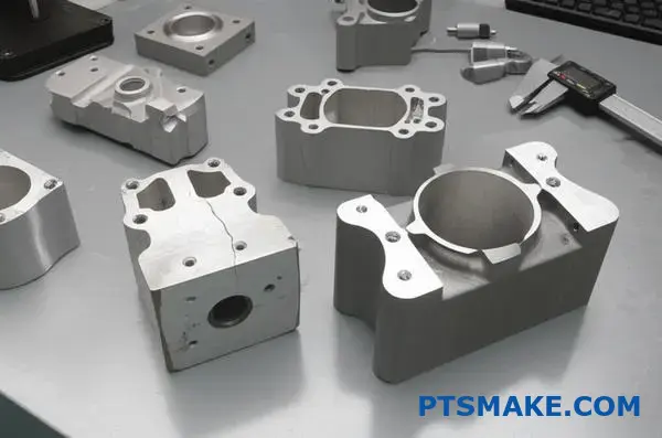
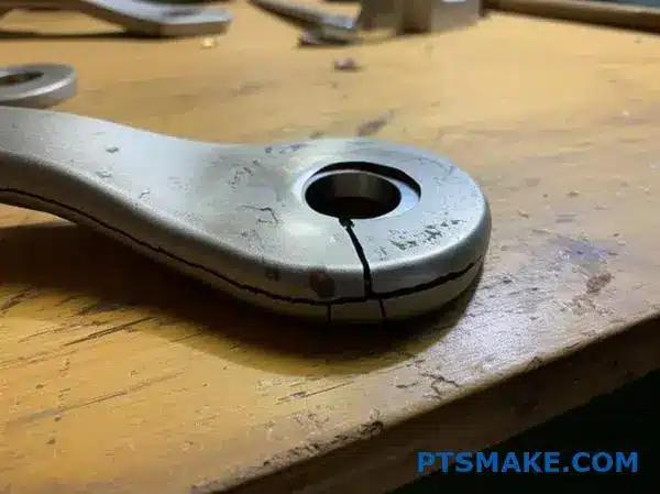
Given a failed part, create a full root cause analysis report.
Let’s walk through a real-world example. A client recently came to us with a critical part that was cracking unexpectedly during assembly.
This is a common but complex problem. Instead of guessing, we immediately applied a structured methodology.
We use tools like the fishbone diagram. This helps organize our brainstorming and ensures we don’t miss any potential causes. It visualizes every possible factor.
Brainstorming with the Fishbone Diagram
The fishbone diagram, or Ishikawa diagram, is perfect for this. It lets us map out potential causes across several key categories. For the cracking issue, we focused on five areas.
Man
Was there operator error? Inconsistent handling or assembly techniques can introduce stress. We reviewed training records and observed the assembly process directly.
Method
The process itself could be flawed. We checked parameters like injection speed and cooling rates. Incorrect settings can create high levels of Residual Stress9, leading to cracks.
Machine
Was the equipment calibrated correctly? We inspected the injection molding machine for wear, inconsistent pressure, and temperature fluctuations.
Material
Material defects are a frequent culprit. We analyzed the polymer batch for impurities or incorrect specifications. Sometimes, a part designed for a robust process might fail if a less experienced die casting manufacturer supplied a substandard alloy.
Measurement
Are the inspection tools accurate? If a caliper or gauge is off, parts might pass inspection even with critical dimensional flaws that cause stress concentration.
Developing a Verification Plan
After brainstorming, we created a clear plan to test our hypotheses. This step is about gathering data, not opinions.
| Potential Cause | Verification Method | Responsible Party |
|---|---|---|
| Incorrect Cooling Rate | Run test batches with varied cooling profiles. | Engineering Team |
| Material Contamination | Send material samples to a lab for analysis. | Quality Control |
| Operator Assembly Error | Video-record assembly; provide revised work instructions. | Production Lead |
This structured approach transforms a complex problem into a series of manageable questions. It moves us from "What happened?" to "Why did it happen?" and finally, "How can we prevent it?"
This case demonstrates how a fishbone diagram helps map potential failure points. By systematically creating and executing a verification plan, we can efficiently identify the true root cause and implement effective, lasting solutions.
How do you apply Design for Manufacturability (DFM) principles?
Applying DFM isn’t just theory. It’s about practical changes before production begins. Let’s look at a common scenario. We receive a part drawing for die casting.
Initial Part Analysis
First, we analyze the design for potential issues. We look for sharp corners, thick sections, and vertical walls. These features often cause manufacturing problems. They can lead to defects and higher costs.
Key Areas for Improvement
Our goal is to improve die fill and reduce defects. We also want to simplify the mold design. Small adjustments can make a huge difference in the final product’s quality and cost.
| Problem Area | Proposed DFM Solution |
|---|---|
| Sharp Internal Corners | Add generous radii |
| Non-Uniform Walls | Redesign for consistent thickness |
| Vertical Walls | Apply draft angles |
| Complex Undercuts | Simplify or eliminate if possible |
These changes make the part easier to produce.
Enhancing Material Flow and Part Ejection
Good DFM ensures molten metal flows smoothly into the mold. This is crucial for avoiding defects. Uniform wall thickness is the first step. It prevents material from cooling too quickly in thin sections or too slowly in thick ones.
This consistency helps prevent sink marks and internal voids. It ensures the part is strong and looks good. A good porosity10 level is a key quality indicator.
Adding Draft Angles and Radii
Next, we add draft angles. Even a small angle, like 1-2 degrees, allows the part to be easily ejected from the mold. This prevents drag marks and damage to both the part and the tool.
We also add generous radii to all corners. Sharp corners create stress points and can crack. They also disrupt metal flow during injection. Smooth, rounded corners improve the part’s structural integrity. Any experienced die casting manufacturer will highlight these areas first.
| Design Change | Primary Benefit | Secondary Benefit |
|---|---|---|
| Uniform Wall Thickness | Prevents sink marks and voids | Improves material flow |
| Draft Angles | Eases part ejection | Reduces tooling wear |
| Generous Radii | Reduces stress concentrations | Enhances die fill |
By working together on these design details, we create a part that is not only functional but also optimized for efficient, high-quality production.
Applying DFM principles to a part drawing before production is critical. Changes like adding draft angles, ensuring uniform walls, and using radii improve material flow, reduce porosity, and simplify tooling. This leads to better parts and lower costs.
How would you implement a traceability system for critical parts?
Designing a real-world traceability system requires a clear, step-by-step plan. Let’s outline one for a critical casting.
The goal is to track it from its origin. We start with the raw metal batch.
The Part’s Digital Journey
We then follow it to the specific machine and time of casting. Finally, we link all this information to its final inspection data.
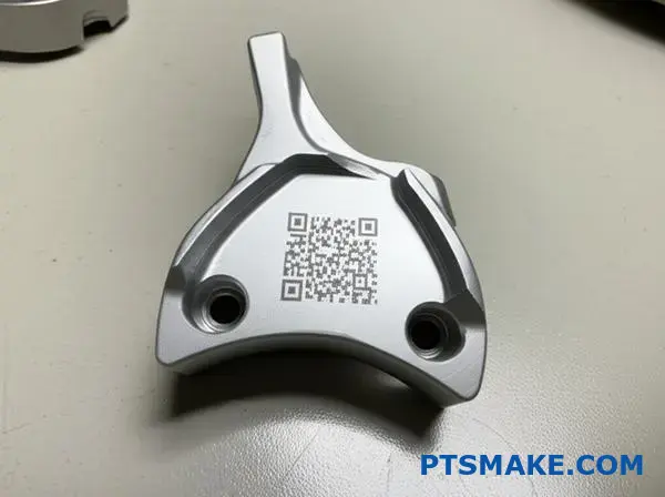
A laser-etched QR code is the key to connecting these stages.
| Stage | Data to Capture | Identification Method |
|---|---|---|
| Material | Metal Batch ID & Specs | Supplier Certificate |
| Production | Machine ID & Timestamp | Internal System Log |
| Inspection | Key Metrics & Pass/Fail | QR Code Scan |
This creates a complete, unchangeable record for every single part. It is the foundation of modern quality control.
A Practical System Design
The core principle is to create a "digital birth certificate" for each casting. This certificate follows the part throughout its life. It ensures accountability and simplifies any potential root cause analysis down the line.
Step 1: Raw Material Logging
When a new batch of metal arrives, it’s assigned a unique internal lot number. This number is logged in our system. It is directly linked to the supplier’s material certificates. This is our starting point.
Step 2: Linking Production Data
At the casting station, the operator scans the metal lot number. The system automatically captures the machine ID, cycle parameters, and an exact timestamp. This creates a snapshot of the part’s creation environment.
A unique QR code is then laser-etched onto the casting. This permanent mark is crucial. It must withstand any subsequent processes, like finishing or heat treatment.
The process of Data Aggregation11 is where the system’s power lies. It combines these separate data points into a single, cohesive record.
As a die casting manufacturer, we find this level of detail is essential for clients in aerospace and automotive.
| Data Point | Source | Linked Via |
|---|---|---|
| Material Certificate | Supplier | Internal Batch ID |
| Process Parameters | Casting Machine | Timestamp & Part QR |
| Dimensional Report | CMM / Inspection | Part QR Code |
This structure ensures that any single part can be traced back to its exact origins and manufacturing conditions.
We’ve outlined a practical traceability system for castings. Using laser-etched QR codes, we link each part to its material batch, production details, and inspection results, creating a complete digital history for every component.
How do emerging technologies impact a die casting manufacturer?
Looking ahead is crucial. The future of die casting is not a distant concept. It’s being shaped by technologies available today. A smart die casting manufacturer must adapt.
We are focused on four key areas. These are Industry 4.0, simulation software, 3D printing, and new alloys. Each brings a unique advantage to the table.
The Next Wave of Innovation
These technologies directly impact efficiency, quality, and cost. They are not just trends; they are tools for building a competitive edge. Understanding them is key.
| Technology | Primary Advantage |
|---|---|
| Industry 4.0 | Process Optimization |
| Simulation Software | Defect Prevention |
| 3D Printed Molds | Cycle Time Reduction |
| New Alloys | Improved Part Performance |
These tools change how we approach projects, from initial design to final production. They allow for a more proactive and precise manufacturing process.
To stay competitive, we must look at the practical side of these innovations. It’s not about adopting everything at once. It’s about smart integration.
Evaluating Practical Impact
Each technology offers a different return on investment. The key is to know which one solves your biggest problem.
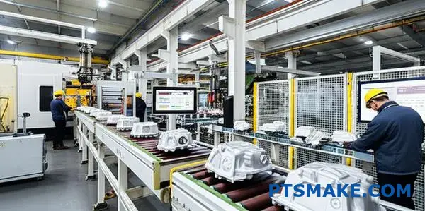
Industry 4.0: The Smart Factory
Industry 4.0 connects machines and systems. It provides real-time data from the factory floor. This allows for predictive maintenance, reducing unexpected downtime. Based on our tests, this can boost equipment uptime by over 15%.
Simulation Software: Getting it Right First
Software like Magmasoft is a game-changer. Before we cut any steel for a mold, we simulate the entire injection process. This allows us to predict and solve potential problems like porosity or shrinkage. We use complex methods like Finite Element Analysis12 to visualize metal flow and cooling patterns. This drastically cuts down on costly and time-consuming mold trials.
3D Printed Mold Components
Additive manufacturing allows us to create mold inserts with highly complex internal cooling channels. These conformal cooling lines follow the part’s shape precisely. This leads to more uniform cooling, which can reduce cycle times and improve part quality.
New High-Performance Alloys
Clients constantly push for lighter and stronger components. New aluminum and magnesium alloys meet these demands. While they can be more challenging to cast, they open doors to new applications in aerospace and automotive industries.
So, which provides the biggest competitive advantage? In our experience, simulation software offers the most immediate and significant impact. It directly improves part quality and slashes development lead times, addressing major client pain points.
Evaluating emerging technologies is vital. While Industry 4.0, 3D printing, and new alloys offer distinct benefits, simulation software provides the most substantial immediate advantage for a die casting manufacturer by ensuring quality and speed before production even begins.
Start Your Project with PTSMAKE – Precision Die Casting Experts
Ready to elevate your die casting project? Trust PTSMAKE for high-quality, precision components and full project support, from RFQ through production. Contact us now for a prompt quote and let our experience in alloy selection, defect prevention, and advanced manufacturing transform your next product.

Learn how this internal crystal structure directly impacts material strength and performance. ↩
Discover how this thermal property affects the integrity and grain structure of the final cast part. ↩
Learn how this metallurgical process affects your part’s durability and performance. ↩
Explore how this process improves aluminum’s surface hardness and allows for vibrant, durable color finishes. ↩
Learn about the types of porosity and how to prevent them in your casting design. ↩
Learn how a material’s flow characteristics directly impact manufacturing choices and final part quality. ↩
Understand how this crucial document maps out the entire manufacturing journey for quality assurance. ↩
Learn how this statistical tool ensures your measurement systems are reliable for quality control. ↩
Learn how internal material stresses can cause unexpected failure, even without external loads. ↩
Learn how to identify and prevent casting defects to enhance your part’s structural integrity. ↩
Learn how combining data from various sources provides deeper insights for quality control. ↩
Learn how this powerful method simulates physical phenomena to predict part performance and prevent manufacturing defects. ↩