Manufacturing engineers face a constant challenge: getting consistent, high-quality anodized aluminum parts that meet exact specifications. Many struggle with defects, color variations, and performance issues because they lack deep understanding of the underlying electrochemical processes.
Anodizing is a controlled electrochemical process that converts the aluminum surface into aluminum oxide through electrolytic oxidation, creating a protective and decorative coating that grows from the base metal itself rather than being applied on top.
This guide covers everything from basic electrochemical principles to advanced troubleshooting techniques. You’ll learn how different aluminum alloys respond to anodizing, master the distinctions between Type I, II, and III processes, and discover practical solutions for common quality issues that can save you time and costly rework.
What is the core electrochemical principle of anodizing?
Many people see anodizing as just another surface coating. But it’s a far more fundamental process. It’s a controlled electrochemical reaction. We aren’t just adding a layer of paint; we’re intelligently growing a new surface directly from the aluminum part itself. This is the key to its strength.
The Core Setup
To understand this, you need to know the four main players in the process. Each one has a critical role in the transformation. The setup is simple but the reaction is complex.
| Component | Role in Anodizing |
|---|---|
| Anode (The Part) | The aluminum workpiece, which is the positive electrode. |
| Cathode | The negative electrode, used to complete the circuit. |
| Electrolyte | An acidic solution that carries the electric current. |
| DC Power Source | The engine that drives the entire reaction. |
This setup creates a powerful circuit to start the aluminum’s transformation.
The Electrochemical Transformation Unveiled
When we apply a direct current (DC), the process begins. The aluminum part, acting as the anode (positive electrode), is submerged in an acidic electrolyte1. The current flowing through this circuit forces a highly controlled oxidation, turning the surface into aluminum oxide. It is not rust; it’s a precise, crystalline structure.
The Ionic Movement
This isn’t a passive process. The electrical current causes ions to move. Negatively charged oxygen ions from the electrolyte are pulled towards the positively charged aluminum surface.
Simultaneously, positively charged aluminum ions from the workpiece are drawn outward from the surface. Where these two types of ions meet, they react. This reaction forms aluminum oxide (Al₂O₃), the very substance that gives an anodized finish its incredible durability and corrosion resistance.
The layer grows both into the substrate and out from it. Because it’s grown from the base material, it is fully integrated with the aluminum part. This is why it can’t chip or peel like paint.
Anodizing vs. Surface Coating
It’s helpful to see how this differs from traditional coatings. In our projects at PTSMAKE, we choose anodizing when component integrity is paramount.
| Feature | Anodizing | Painting / Plating |
|---|---|---|
| Bonding | Fully integrated with the metal | Sits on top of the surface |
| Process | Electrochemical conversion | Simple material deposition |
| Durability | Extremely high; resists chipping | Can chip, peel, or flake off |
| Result | A new, harder surface | An additional surface layer |
This distinction is crucial for any engineer or designer.
Anodizing is an engineered electrochemical process. It transforms the surface of an aluminum part into a durable, corrosion-resistant aluminum oxide layer. This integrated layer offers superior performance compared to coatings that simply sit on the surface.
Why are specific aluminum alloys chosen for anodizing?
The success of anodizing heavily depends on the aluminum alloy itself. Think of it like baking a cake. The ingredients you use completely change the final result.
The same is true for aluminum. The specific elements mixed into it, like magnesium or silicon, directly impact the anodized finish.
The Influence of Alloying Elements
Each alloying element reacts differently during the anodizing process. Some help create a perfect finish, while others can cause major issues. It’s crucial to understand these effects before selecting a material for your project.
Key Elements and Their Impact
Magnesium (Mg) helps produce a clear and bright finish. Silicon (Si), however, often results in a dark gray, non-uniform appearance. Copper (Cu) can lower the final corrosion resistance.
| Alloying Element | Effect on Anodizing | Typical Finish |
|---|---|---|
| Magnesium (Mg) | Excellent | Bright, Clear |
| Silicon (Si) | Poor | Dark, Gray |
| Copper (Cu) | Fair, but complex | Yellowish Tint |
A Practical Comparison of Anodized Alloys
Let’s compare how different popular alloys perform. Choosing the right alloy from the start is a critical step we focus on at PTSMAKE. It saves time and prevents costly mistakes down the line. The wrong choice can ruin the aesthetic and functional goals of a part.
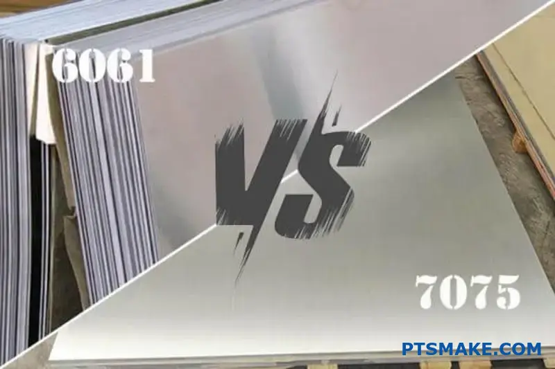
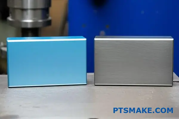
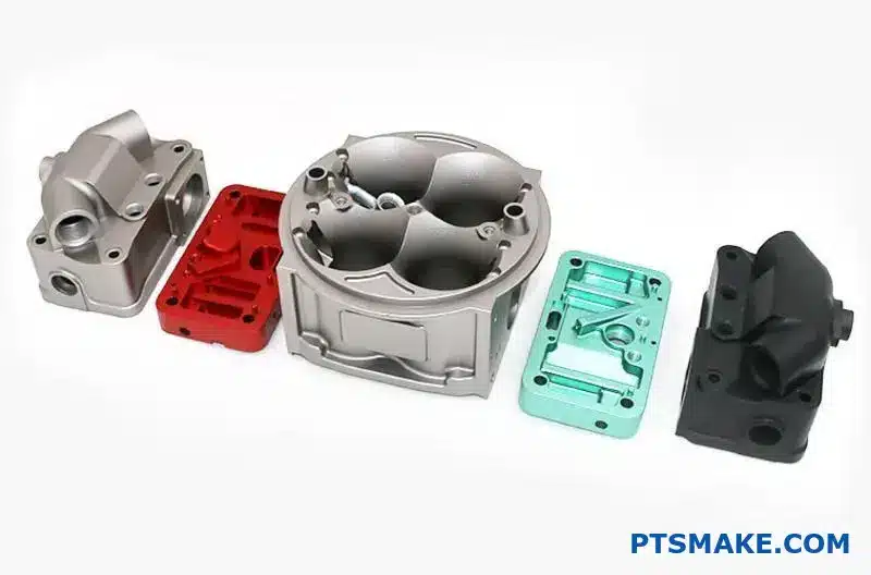
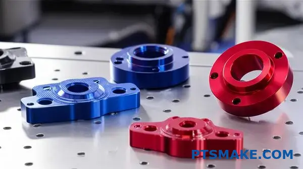
6061 Alloy: The Versatile Choice
6061 is a workhorse for a reason. It contains magnesium and silicon, which allows it to form a strong, uniform, and clear anodic layer. This makes it an excellent candidate for dyeing in various colors. It consistently delivers great cosmetic and protective results.
7075 Alloy: High Strength, High Challenge
7075 is known for its incredible strength, but its high zinc and copper content complicates anodizing. These elements can create inconsistencies in the oxide layer. This often results in a thinner coating with a natural yellowish or brownish hue. The presence of intermetallic compounds2 makes achieving a uniform, decorative finish difficult.
A380 Cast Alloy: The Silicon Issue
Cast alloys like A380 present the biggest challenge. They contain high levels of silicon, over 8%. This silicon does not anodize. It leaves behind a dark, often blotchy gray finish that is unsuitable for most cosmetic applications.
| Alloy | Key Elements | Anodized Color (Natural) | Uniformity | Protective Quality |
|---|---|---|---|---|
| 6061 | Magnesium, Silicon | Clear | Excellent | Excellent |
| 7075 | Zinc, Copper | Yellowish/Brownish | Fair | Good |
| A380 | Silicon, Copper | Dark Gray, Mottled | Poor | Fair |
Alloying elements are the deciding factor in anodizing success. An alloy like 6061 provides a beautiful, uniform finish. In contrast, high-silicon cast alloys or high-copper alloys like 7075 present significant challenges for achieving a high-quality cosmetic appearance and uniform protection.
Beyond appearance, what are the primary functional goals of anodizing?
While a great finish is important, the true value of anodizing lies in its functional enhancements. This process transforms a simple aluminum surface into a high-performance barrier. It’s about adding real engineering value.
We focus on three primary goals for our clients’ parts. These upgrades are crucial for performance and longevity.
Superior Corrosion Resistance
Anodizing creates a stable oxide layer. This layer is much thicker than the natural one, protecting the metal from moisture and chemicals.
Increased Hardness
The anodized layer is incredibly hard, often approaching the hardness of diamond. This improves wear resistance significantly.
Electrical Insulation
Unlike raw aluminum, the anodized surface does not conduct electricity. This is a critical feature for many electronic applications.
| Feature | Raw Aluminum | Anodized Aluminum |
|---|---|---|
| Corrosion | Poor | Excellent |
| Hardness | Soft | Very Hard |
| Insulation | Conductive | Insulative |
At PTSMAKE, we guide clients to the right anodizing type based on their specific functional needs. It’s not a one-size-fits-all solution. The environment where the part will be used is the most important factor.
Real-World Engineering Applications
Battling the Elements with Corrosion Resistance
For parts exposed to harsh conditions, corrosion resistance is non-negotiable. Think about components used in marine environments. We’ve worked on parts for underwater robotics where saltwater exposure is constant. Standard aluminum would fail quickly. Anodizing provides a robust shield, preventing degradation and ensuring the device operates reliably for its entire service life. It’s a simple step that saves costly future repairs.
Enhancing Durability with Surface Hardness
In machinery, parts are often subjected to friction and abrasion. Hardcoat anodizing (Type III) is the answer here. It creates an extremely durable surface, ideal for components like pistons, gears, or sliding mechanisms. This process dramatically extends the part’s lifespan. It reduces maintenance needs and ensures consistent performance. The hard layer protects the softer aluminum core from mechanical stress.
Ensuring Safety with Electrical Insulation
Many electronic devices use aluminum for its excellent heat dissipation. However, its conductivity can be a problem. Anodizing creates an electrically insulating layer. This prevents short circuits between sensitive components and the housing. We often use this for heatsinks and enclosures. This property ensures the final product is both safe and reliable, as it improves the dielectric strength3 of the surface.
Anodizing is a key process for creating functional, high-performance parts. It enhances corrosion resistance, boosts surface hardness for better wear, and provides essential electrical insulation. These benefits are crucial in demanding industries.
What does the term ‘throwing power’ mean in practice?
In anodizing, "throwing power" is a crucial concept. It describes the ability of the process to create a uniform oxide layer on all surfaces of a part.
This is especially important for complex geometries. Think about parts with deep holes, sharp internal corners, or tight crevices. Good throwing power ensures these hard-to-reach areas get coated just as well as the flat, exposed surfaces. Without it, you get an inconsistent finish and uneven protection.
Key Influencing Factors
Several variables determine the effectiveness of throwing power. Understanding them is key to achieving a quality finish.
| Factor | Description |
|---|---|
| Electrolyte Type | The chemical solution used directly impacts ion flow. |
| Temperature | Affects the conductivity and reaction rate of the process. |
| Part Geometry | The shape of the part itself can help or hinder the process. |
A Deeper Look at Anodizing Factors
Achieving a consistent anodized layer on complex parts is a challenge we often tackle at PTSMAKE. The success hinges on carefully controlling the process variables that influence throwing power. Let’s break down the most critical ones.
Electrolyte Composition and Concentration
The type of acid used in the electrolyte bath is a primary driver. For example, chromic acid anodizing generally offers better throwing power than the more common sulfuric acid process. This makes it a preferred choice for parts with very complex shapes, like those in aerospace applications. The concentration of the acid also matters. A lower concentration can sometimes improve throwing power by altering the solution’s conductivity.
Operating Temperature
Temperature control is non-negotiable. A higher bath temperature increases the electrolyte’s conductivity, which can improve throwing power. However, it also accelerates the dissolution of the oxide layer. This creates a delicate balance. Based on our tests, finding the optimal temperature for a specific alloy and part geometry is essential for a uniform coating without compromising its integrity. The process can also be affected by the Faraday cage effect4 where recessed areas are shielded from the electric current.
Part Geometry and Racking
The part’s design is a major factor.
- Sharp Corners: Electric current concentrates on sharp external corners, leading to thinner coatings in internal corners.
- Deep Holes: It is difficult for the electric current and electrolyte to penetrate deep, narrow holes.
How we mount the part on the rack is also vital. Strategic racking ensures that all surfaces have adequate exposure to the electrolyte and the electric field, minimizing inconsistencies.
In short, throwing power defines how uniformly an anodizing process coats a complex part. It’s not a single setting but a result of balancing electrolyte type, temperature, and part geometry to achieve a consistent, protective finish on every surface.
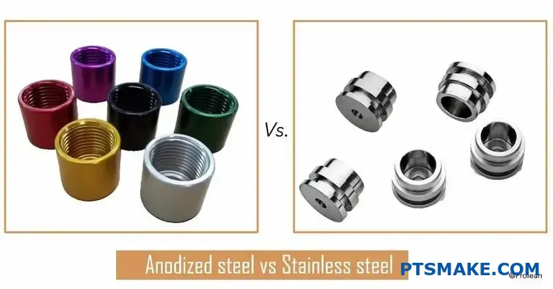
How does anodizing fundamentally differ from electroplating?
The core difference is simple yet profound. Anodizing is a conversion process, while electroplating is an additive one. Think of it like this: anodizing grows a protective layer from the metal itself. It transforms the existing surface.
In contrast, electroplating deposits a completely new layer of a different metal onto the surface. This distinction is crucial. It changes everything from adhesion to final dimensions.
Key Distinctions at a Glance
Understanding this "growth vs. addition" concept is the first step. It dictates how each finish behaves.
| Feature | Anodizing | Electroplating |
|---|---|---|
| Process Type | Conversion Coating | Additive Coating |
| Layer Formation | Grows from base metal | Deposits onto base metal |
| Material | Oxide of base metal | A different metal |
This table shows the fundamental principle behind each process. One transforms, the other covers.
The choice between these two isn’t just about looks. It’s a critical engineering decision driven by first principles. The implications for part performance are significant. At PTSMAKE, we guide clients through this choice daily, ensuring the finish matches the application’s demands perfectly.
Impact on Part Characteristics
Let’s break down how this core difference affects key part features. The method of layer formation directly influences the final product’s performance and a part’s final dimensions. This is a topic we often discuss with clients during the design phase.
Adhesion and Durability
Because an anodized layer is integral to the base metal, its adhesion is perfect. It can’t peel or chip off because it’s part of the substrate5 itself. This makes anodizing extremely durable for high-wear applications.
Electroplating, however, relies on a molecular bond between two different materials. While modern techniques create strong bonds, there’s always a risk of delamination or flaking under stress if the surface preparation isn’t flawless.
Dimensional Changes
This is where precision engineering comes into play. Anodizing grows the layer both inward and outward from the original surface. Typically, about 50% of the layer thickness penetrates the metal, and 50% builds up on the surface.
Electroplating is purely additive. The entire thickness of the plated layer is added to the part’s dimensions. For parts with tight tolerances, this difference is a major factor.
| Aspect | Anodizing Implication | Electroplating Implication |
|---|---|---|
| Adhesion | Integral to part, will not flake | Relies on bond, can delaminate |
| Dimensions | Grows in and out (e.g., 50/50) | Purely additive, increases size |
| Base Material | Must be a suitable metal (Al, Ti) | Can be applied to many materials |
Understanding these implications ensures the final part meets all specifications, a core principle of our work at PTSMAKE.
Anodizing fundamentally alters the existing surface, creating an integrated protective layer. Electroplating adds a new, separate metal layer on top. This distinction directly impacts adhesion strength, dimensional tolerances, and the material properties of the finished component.
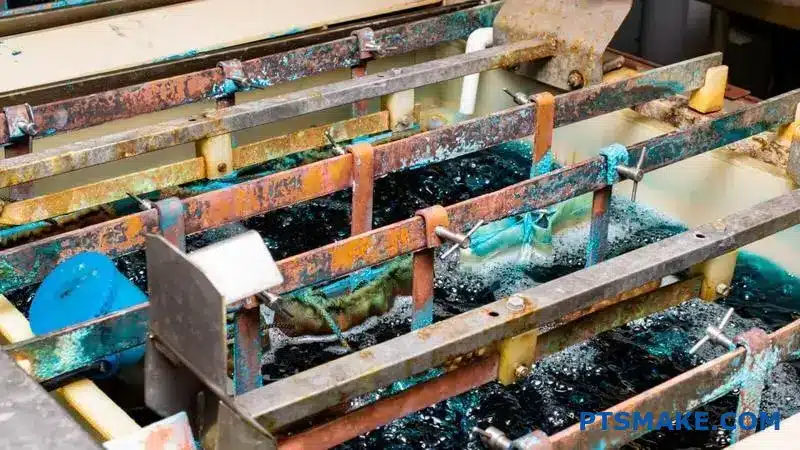
What are the main environmental concerns of anodizing wastewater?
The rinse water from the anodizing process may seem clear, but it carries significant environmental risks. The two main concerns are the dissolved metals and the extreme pH levels of the water. These factors make the wastewater highly toxic.
Key Contaminants
Dissolved aluminum is a primary pollutant, originating from the parts being treated. Depending on the specific anodizing process, other heavy metals like chromium might also be present. These metals are harmful to aquatic ecosystems.
The pH Challenge
The wastewater is either highly acidic or highly alkaline. Discharging it without treatment can drastically alter the pH of natural water bodies, causing immediate harm to fish and plant life.
| Contaminant | Primary Source | Environmental Threat |
|---|---|---|
| Dissolved Aluminum | Etching of parts | Toxic to fish and aquatic invertebrates |
| Other Heavy Metals | Coloring/Sealing baths | Can accumulate in the food chain |
| Extreme Acidity/Alkalinity | Process baths | Destroys aquatic habitats |
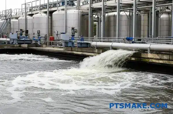
Treating this wastewater isn’t just about following rules; it’s about responsible manufacturing. In my experience, a robust treatment system is essential for any reputable anodizing operation. The process primarily involves neutralizing the pH and removing the dissolved heavy metals before discharge.
The First Step: pH Neutralization
The initial and most critical step is to adjust the pH. If the water is acidic, we carefully add an alkaline solution. If it’s alkaline, we add an acid. We aim for a neutral pH, typically between 6.0 and 9.0. This step is vital because it prepares the water for effective metal removal. An incorrect pH can prevent the next stage from working at all.
The Second Step: Metal Precipitation and Removal
With the pH corrected, we introduce chemicals that react with the dissolved metals. This reaction, known as precipitation, transforms the invisible dissolved metals into solid, visible particles.
These tiny particles are then encouraged to clump together into larger groups through a process called Flocculation6. These larger, heavier clumps, or "floc," are much easier to separate from the water. In past projects at PTSMAKE, we’ve found that this method is highly effective. The solids are then removed through settling tanks and filtration, leaving clean water behind.
| Treatment Stage | Objective | Common Method |
|---|---|---|
| Equalization | Create uniform wastewater | Mixing in a large holding tank |
| pH Neutralization | Adjust pH to a neutral range | Dosing with acid or alkali |
| Coagulation/Flocculation | Clump solids for easy removal | Adding specific polymers |
| Clarification | Separate solids from water | Settling tanks and filtration |
This two-pronged approach ensures that the water discharged from our facility is safe for the environment. It’s a commitment we take seriously.
Anodizing wastewater is hazardous due to dissolved metals and extreme pH levels. A proper treatment process is crucial. It involves neutralizing the pH first, followed by chemical precipitation and filtration to remove the metals, ensuring compliance and protecting the environment.
What distinguishes Type II from Type III (Hardcoat) anodizing?
Let’s get straight to the point. The choice between Type II and Type III anodizing comes down to your application’s specific needs. It’s a classic trade-off between versatility and extreme performance.
Understanding the Core Trade-Offs
Type II is the reliable workhorse for cosmetic and general corrosion resistance. In contrast, Type III is a specialized process. It creates a surface ready for the harshest environments. The differences start at the fundamental process level.
Process Defines Performance
The operating parameters directly dictate the final properties of the coating. We’ll explore exactly how temperature and electricity create two very different outcomes.
The ‘why’ behind the differences is rooted in the process chemistry. Type III anodizing runs in a much colder electrolyte bath, typically near freezing. This cold temperature dramatically slows the sulfuric acid’s natural tendency to dissolve the aluminum oxide as it forms.
At the same time, we apply a much higher electrical current. This forces the oxide layer to build up much faster than it can dissolve. This controlled competition creates a very different pore morphology7. The resulting oxide layer is incredibly dense and thick. It has a more ordered, compact structure. This is what gives hardcoat its superior hardness and wear resistance.
Conversely, Type II uses a room-temperature bath. The oxide growth and dissolution rates are more balanced. This results in a more porous, less dense layer that is excellent for accepting dyes but lacks the raw durability of Type III. In our work at PTSMAKE, we always guide clients based on the final use case. A decorative part doesn’t need the expense or properties of hardcoat. A high-wear industrial component absolutely does.
Comparison: Type II vs. Type III Anodizing
| Parameter | Type II (Sulfuric) | Type III (Hardcoat) |
|---|---|---|
| Operating Temperature | 18-22°C (65-72°F) | 0-4°C (32-40°F) |
| Current Density | 12-25 A/ft² | 25-40 A/ft² |
| Layer Thickness | 5 – 25 µm (0.0002" – 0.001") | 25 – 125 µm (0.001" – 0.005") |
| Hardness | 200-400 HV | 600-700 HV (Rockwell 60-70C) |
| Abrasion Resistance | Good | Excellent |
| Typical Applications | Consumer electronics, architectural parts | Aerospace components, pistons, gears |
In summary, the choice is clear. Type II anodizing provides good corrosion resistance and is ideal for dyeing. Type III creates a thicker, harder surface for high-wear applications where durability is the primary concern. The process dictates the properties.
When would you specify Type I (Chromic Acid) anodizing?
Type I anodizing is a highly specialized process. You won’t see it used as often as Type II. But for certain critical applications, it’s the only real choice.
This is especially true in the aerospace industry. We specify Type I for parts with complex geometries. Think of components with tight seams, folds, or blind holes. It’s also chosen when preserving the material’s original fatigue strength is non-negotiable.
Key Scenarios for Type I
The thin film it creates offers excellent corrosion resistance. It has a minimal impact on the part’s dimensions and structural integrity.
| Feature | Type I (Chromic Acid) | Type II (Sulfuric Acid) |
|---|---|---|
| Fatigue Strength Impact | Minimal | Can be significant |
| Trapped Acid Risk | Low risk of corrosion | High risk of corrosion |
| Film Thickness | Very thin (~0.5-2.5 µm) | Thicker (~2-25 µm) |
| Primary Application | Aerospace, Bonded Assemblies | General Purpose, Decorative |
This makes it perfect for parts that will be flexed or vibrated constantly during their service life.
Aerospace and Complex Geometries
In aerospace, every gram and every cycle of stress matters. That’s why Type I anodizing is often the go-to standard for aluminum aircraft components. The process has a very low fatigue debit8, meaning it doesn’t significantly reduce the part’s ability to withstand cyclic loading. For parts like fuselage skins or wing components, this is a critical safety factor.
The Trapped Acid Dilemma
Now, let’s talk about complex parts. Imagine a component with overlapping joints or deep, narrow holes. During the anodizing process, the acid solution can get trapped in these features. If you use Type II (sulfuric acid), any trapped residue will continue to eat away at the aluminum, causing corrosion from the inside out. This is a catastrophic failure waiting to happen. Chromic acid, however, is far less aggressive. Any small amount that gets trapped is self-passivating and won’t cause further damage. This is a key reason we recommend it for welded parts and complex assemblies at PTSMAKE.
The Environmental Challenge
The major drawback of Type I is its chemistry. It uses hexavalent chromium, a substance under tight environmental and health regulations. This makes the process more expensive and complex to manage due to waste treatment and safety requirements. As a result, it is only specified when its unique engineering benefits are absolutely essential for the part’s performance and safety.
Type I anodizing is a niche solution for high-stakes applications. It is ideal for critical aerospace parts, complex assemblies where acid entrapment is a concern, and components where maintaining fatigue strength is paramount despite its environmental challenges.
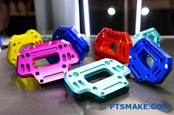
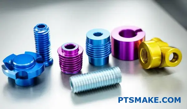
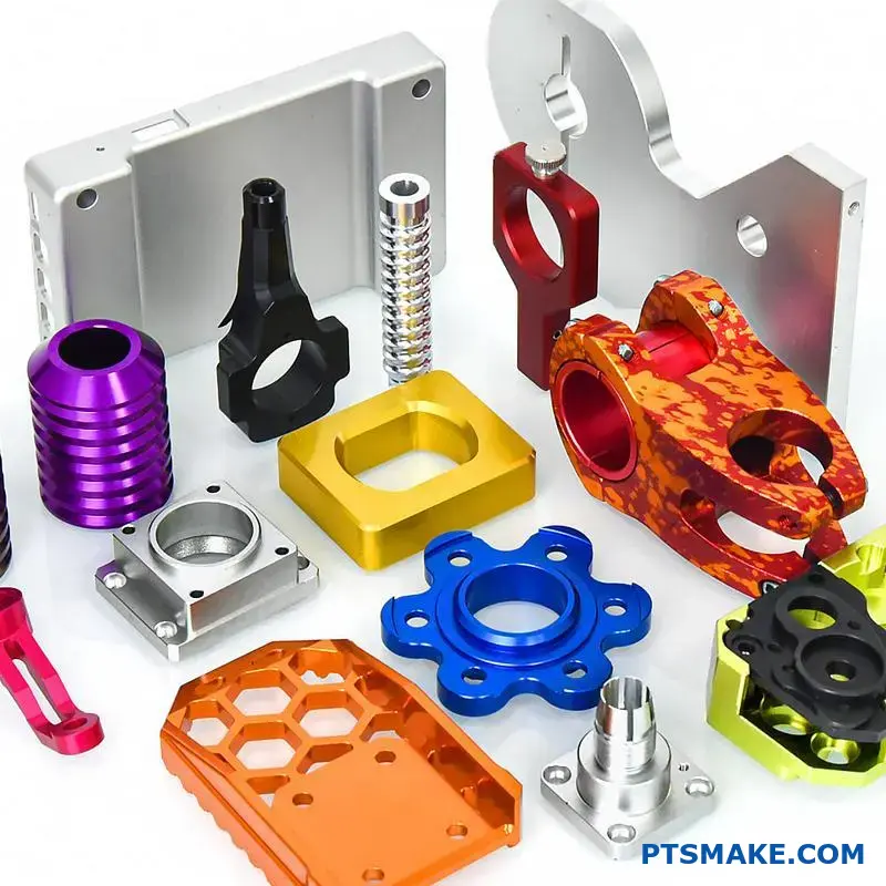
How do you achieve color in anodized parts?
Coloring an anodized part is not like painting. We are essentially filling the microscopic pores created during the anodizing process. The method we choose directly impacts the final look, durability, and cost.
There are three primary ways to achieve color. Each has its own mechanism and ideal use case. Let’s briefly look at them.
Three Main Coloring Methods
| Coloring Method | Basic Mechanism | Common Colors |
|---|---|---|
| Dyeing | Pores absorb organic/inorganic dyes | Wide range, very vibrant |
| Electrolytic | Metal salts deposited in pores | Bronze, black, champagne |
| Integral | Color formed during anodizing | Grays, bronzes (alloy-dependent) |
Choosing the right one is crucial for your project’s success.
Let’s dive deeper into how these methods work. Each one offers a different balance of aesthetics, performance, and cost. Understanding these trade-offs is key to making the right choice for your application.
Organic & Inorganic Dyeing
This is the most common method for achieving a wide spectrum of colors. After anodizing, the part is simply dipped into a dye solution. The porous oxide layer absorbs the dye, much like a sponge.
The color palette is nearly limitless. However, organic dyes can fade over time with UV exposure. Their lightfastness9 varies. This method is perfect for consumer electronics or parts not intended for long-term outdoor use.
Electrolytic Coloring
Also known as "two-step" coloring, this process is more robust. After anodizing, the part is placed in a second electrolytic bath containing metal salts. An AC voltage deposits these salts into the base of the pores.
The color comes from the optical effects of these metal particles. This results in very durable, UV-resistant colors like bronze, black, and champagne. In our experience at PTSMAKE, this is a top choice for architectural and automotive applications where durability is critical.
Integral Coloring
With integral coloring, the color is created during the anodizing process itself. Specific alloys and electrolytes are used to form the colored anodic layer in one step. The color is an integral part of the oxide layer, making it extremely durable.
The color range is limited to earthy tones like bronze, gray, and black. The final shade depends heavily on the aluminum alloy and anodizing parameters. It’s the most durable but often the most expensive option.
In short, color in anodizing is achieved by filling the anodic pores. The choice between dyeing, electrolytic, and integral methods depends on your specific needs for color variety, durability against sunlight, and overall performance.
What is the practical significance of MIL-A-8625 standard?
The MIL-A-8625 standard is more than just a technical document. For us in precision manufacturing, it is a language of quality. It ensures that when you request an anodized finish, you get a predictable and reliable result every time.
This specification is critical for aluminum parts. It clearly defines the types of anodic coatings and their classes. This removes ambiguity and guarantees performance. Following this standard means your components will meet specific requirements for durability and function, which is essential in demanding industries.
The Main Anodizing Types
| Type | Common Name | Key Feature |
|---|---|---|
| Type I | Chromic Acid Anodize | Thin film, excellent corrosion resistance |
| Type II | Sulfuric Acid Anodize | General purpose, good for dyeing |
| Type III | Hardcoat Anodize | Extremely hard and durable |
This framework is the foundation for consistent, high-quality anodizing.
Diving Deeper into MIL-A-8625 Types and Classes
Let’s break down the standard further. The "Type" specifies the anodizing process used, which directly impacts the coating’s properties.
Anodic Coating Types
Type I uses chromic acid. It creates the thinnest film, making it ideal for parts with tight tolerances that cannot afford dimensional changes. It is also a great paint base.
Type II is the most common. It uses sulfuric acid and produces a coating with good corrosion and abrasion resistance. Its porous nature makes it perfect for adding color.
Type III, or hardcoat anodizing, also uses sulfuric acid but at lower temperatures and higher voltages. This creates a much thicker and harder layer. It is for parts needing maximum wear resistance.
Coating Classes
Within these types, there are two classes:
- Class 1 is non-dyed. It retains the natural color of the anodic coating.
- Class 2 is dyed. This adds color to the part, such as black, red, or blue.
At PTSMAKE, specifying a part to this standard removes all guesswork. When a client needs a durable, black component, we know that MIL-A-8625 Type III, Class 2 is the precise requirement. This standard provides clear testable parameters for coating thickness, weight, and corrosion resistance10. This ensures every piece we deliver meets the exact performance and quality levels demanded by industries like aerospace and medical.
MIL-A-8625 is a practical tool. It translates client needs into specific, repeatable manufacturing instructions. This guarantees that every anodized part meets stringent quality, performance, and testing standards, ensuring reliability in its final application.
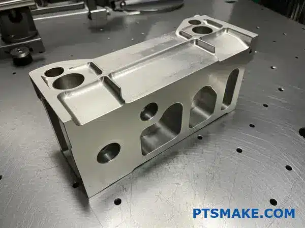
How does a part’s geometry affect anodizing quality?
A great design for machining doesn’t always guarantee a perfect anodized finish. Certain geometric features can create significant challenges during the anodizing process, leading to defects that compromise both appearance and performance.
We’ll explore three of the most common design pitfalls that I often see. These include sharp inside corners, deep blind holes, and large, uninterrupted flat surfaces. Understanding these challenges is the first step to avoiding them.
Here is a quick overview of the issues:
| Design Pitfall | Potential Anodizing Defect |
|---|---|
| Sharp Inside Corners | Voids, Cracks, or ‘Undercutting’ |
| Blind Holes | Trapped Chemicals & Post-Process Staining |
| Large Flat Surfaces | Flow Marks & Color Inconsistency |
Good anodizing quality starts long before the part reaches the finishing tank; it begins on the drawing board. In our projects at PTSMAKE, we emphasize a Design for Manufacturing (DFM) approach that includes considerations for finishing processes like anodizing. This foresight prevents costly rework and delays.
Addressing Sharp Inside Corners
The electric current used in anodizing flows like water, preferring the path of least resistance. It struggles to reach deep into sharp, 90-degree internal corners. This "current starvation" results in a much thinner, weaker, or even non-existent anodic coating in that area. This weak spot is prone to cracking and corrosion.
Solution: The fix is simple. Always design inside corners with a radius. Even a small radius of 0.5mm can dramatically improve current flow, ensuring a uniform and durable coating.
The Problem with Blind Holes
Blind holes are notorious for trapping fluids. During anodizing, they hold onto cleaning acids and process chemicals. Even with thorough rinsing, it’s difficult to completely clear them out. These trapped chemicals can seep out later, causing ugly streaks and compromising the finish.
This is especially true for threaded holes, where the threads create even more places for liquid to hide.
Challenges with Large, Flat Surfaces
Achieving a perfectly consistent color and finish on a large, flat surface is very difficult. Small variations in bath temperature, agitation, or current density11 can create visible flow marks, blotches, or color inconsistencies. The larger the surface, the more noticeable these minor variations become.
Solution: Whenever possible, break up large, flat areas. You can add subtle grooves, a gentle crown, or specify a bead-blasted texture before anodizing. These features help mask minor imperfections and create a more uniform appearance.
| Problem | Recommended Design Solution |
|---|---|
| Sharp Inside Corners | Add a minimum radius of 0.5mm. |
| Blind Holes | Use through-holes or specify clear drainage orientation. |
| Large Flat Surfaces | Break up the surface with textures or subtle features. |
Avoiding sharp corners, carefully managing blind holes, and breaking up large flat surfaces are crucial design steps. A little foresight here prevents major finishing headaches and is essential for achieving consistent, high-quality anodizing results for your parts.
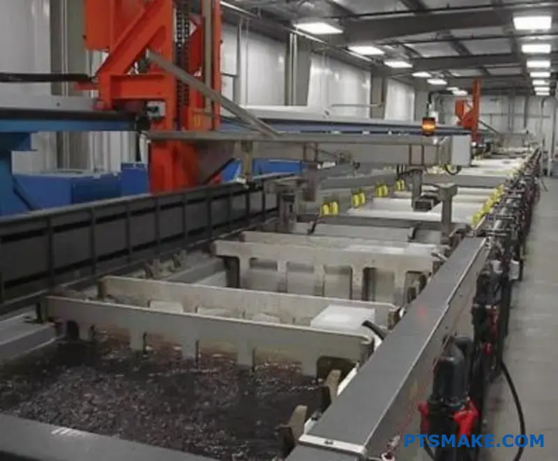
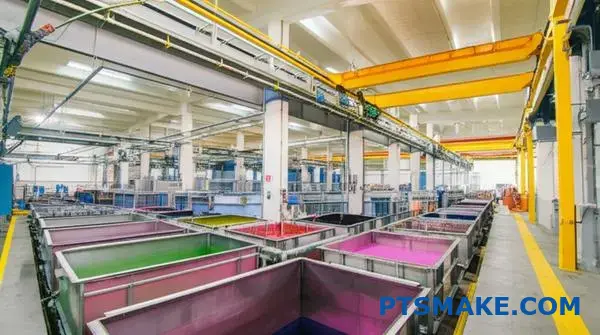
What is the structure of a typical industrial anodizing line?
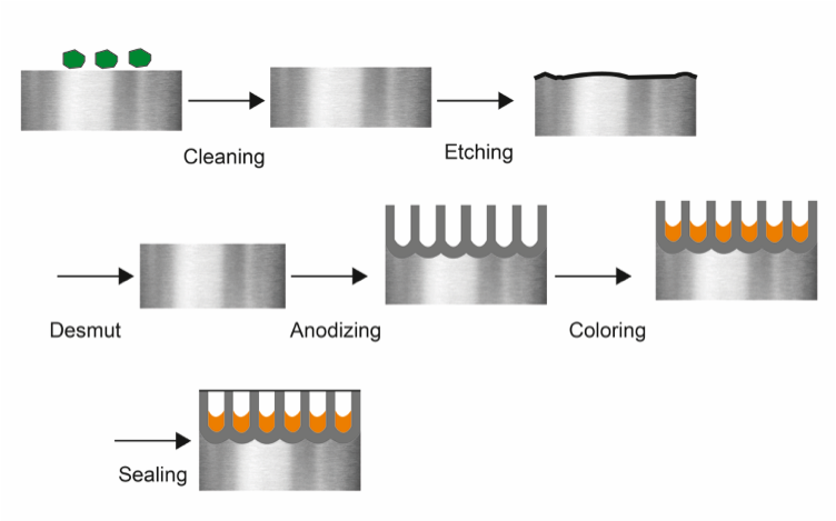
An industrial anodizing line is a highly structured sequence of chemical baths. Think of it as a precise recipe where every ingredient and every step matters. The flow is logical and absolutely critical for a successful finish.
The process moves parts from pre-treatment to the final seal. Rinsing between each active tank is not optional; it is a core part of the process. This prevents cross-contamination of the chemical baths.
The Anodizing Process Flow
Here is a simplified breakdown of the key stations in order.
| Station | Purpose |
|---|---|
| Cleaning / Degreasing | Removes oils, grease, and dirt from machining. |
| Rinse | Washes away cleaning agents. |
| Etching | Creates a uniform matte surface finish. |
| Rinse | Removes residual etching chemicals. |
| De-smutting | Clears away metallic residues left by etching. |
| Rinse | Prepares the surface for the anodizing step. |
| Anodizing | Forms the durable aluminum oxide layer. |
| Rinse | Washes away acid from the anodizing bath. |
| Dyeing (Optional) | Adds color to the porous oxide layer. |
| Rinse | Removes excess dye. |
| Sealing | Closes the pores of the oxide layer. |
This sequence ensures the final product is consistent and meets quality standards.
The importance of this sequence cannot be overstated. Each stage chemically prepares the aluminum surface for the very next step. Any deviation can lead to immediate and often irreversible defects.
Why Sequence and Rinsing are Critical
For example, if de-smutting is skipped after etching, the leftover metallic alloys on the surface will interfere with the electrical current in the anodizing tank. This results in streaks, blotches, or areas where the oxide layer doesn’t form correctly. You cannot simply go back and fix it; the part is often a total loss.
Rinsing is the unsung hero of the entire operation. It’s about achieving chemical purity at each stage. The goal is to eliminate "drag-out," which is the small amount of solution that clings to parts as they move from one tank to the next.
The Impact of Poor Rinsing
Poor rinsing contaminates the subsequent bath. Imagine dragging alkaline etch solution into the acidic anodizing tank. This neutralizes the acid, alters the chemical balance, and compromises the entire bath. The Faradaic efficiency12 of the anodizing process is extremely sensitive to contaminants. In past projects with clients, we’ve seen how even minor impurities can lead to inconsistent oxide layer thickness, affecting both durability and color absorption.
This is why at PTSMAKE, our partners use multi-stage rinsing systems, often with deionized water, to ensure that only a clean aluminum part enters each critical stage.
| Rinsing Method | Impact on Quality |
|---|---|
| Multi-Stage Cascade Rinse | High consistency, stable baths, low defect rate. |
| Single Static Rinse | High risk of contamination, inconsistent finish. |
| No Rinse | Guaranteed process failure and bath contamination. |
Proper rinsing is not just a cleaning step; it is a fundamental process control measure.
A typical industrial anodizing line follows a strict sequence of cleaning, etching, anodizing, and sealing. Meticulous rinsing between each stage is non-negotiable, as it prevents contamination and ensures a high-quality, durable finish for every part we produce.
Can materials other than aluminum be anodized?
Anodizing is not exclusive to aluminum. Other metals, known as valve metals, can also undergo this process. Titanium and magnesium are prime examples.
Each metal reacts differently, producing unique benefits. This expands the applications of anodizing far beyond just aluminum parts.
Titanium’s Unique Properties
Titanium anodizing is often used for color coding. This is especially useful in the medical field. The process enhances biocompatibility, making it safe for implants.
Magnesium’s Protective Layer
Magnesium is highly susceptible to corrosion. Anodizing creates a crucial protective layer. This layer significantly improves its durability and lifespan in various applications.
| Metal | Primary Goal of Anodizing | Key Benefit |
|---|---|---|
| Titanium | Color & Biocompatibility | Medical Identification |
| Magnesium | Corrosion Resistance | Increased Durability |
While the term "anodizing" is used for all these metals, the process and results vary significantly. It’s not a one-size-fits-all solution. Understanding these differences is key to choosing the right material and finish for your project. At PTSMAKE, we guide clients through these choices to ensure optimal performance.
Titanium Anodizing: A Spectrum of Color
Unlike aluminum, titanium anodizing doesn’t typically use dyes. The color comes from an oxide layer that forms on the surface. The thickness of this layer determines the color you see.
This phenomenon is due to light interference. By precisely controlling the voltage during the process, we can create a specific, consistent color. This is a form of electrochemical conversion coating13 where the surface itself is changed. The resulting oxide layer is very thin but also very durable.
This process is critical for medical implants. The colors can be used to identify different sizes or types of components during surgery. The enhanced biocompatibility also ensures the part integrates well with the human body.
Magnesium Anodizing: A Fight Against Corrosion
Magnesium is lightweight but corrodes easily. Anodizing provides a much denser, more corrosion-resistant finish than the metal’s natural oxide layer. It serves as an excellent primer for paint or other coatings.
The table below contrasts the key aspects of anodizing for these metals.
| Feature | Aluminum Anodizing | Titanium Anodizing | Magnesium Anodizing |
|---|---|---|---|
| Layer Type | Porous, thick | Thin, transparent | Dense, protective |
| Coloring | Dyes absorbed into pores | Light interference | Typically opaque |
| Primary Use | Durability, aesthetics | Color, biocompatibility | Corrosion protection |
While aluminum anodizing is common, titanium and magnesium offer unique advantages. Titanium provides color and biocompatibility through a thin oxide layer, while magnesium gets a vital boost in corrosion resistance. The right choice depends entirely on the application’s specific needs.
How do hardcoat properties vary with alloy and thickness?
Thinking of Type III hardcoat as a single, fixed material is a common mistake. The final properties are not universal. They change significantly based on the aluminum alloy you choose and the thickness you specify. This is a critical detail in precision manufacturing.
Your choice of material and coating depth directly impacts the part’s final performance.
The Specification Matrix
Understanding this relationship is key to successful hardcoat anodizing. A stronger alloy doesn’t always guarantee a better coating. The interaction between the two is what truly matters.
Below is a simplified table showing this concept.
| Property | Factor: Alloy | Factor: Thickness |
|---|---|---|
| Hardness | Higher with purer alloys | Generally increases |
| Abrasion Resistance | Varies by alloying elements | Improves up to a point |
| Brittleness | Can increase | Increases significantly |
This matrix helps visualize how interconnected these factors are for the final anodizing outcome.
Deeper Dive into Alloy and Thickness Effects
The interplay between the base alloy and coating thickness is where the real engineering happens. It’s not just about picking the strongest alloy or the thickest coating. The optimal combination depends entirely on the application’s demands.
Alloy Composition’s Role
Different aluminum alloys contain varying elements like copper, silicon, and zinc. During anodizing, these elements can interfere with the formation of the aluminum oxide layer. This impacts the coating’s uniformity, density, and hardness. The coating’s microstructure14 is directly affected.
For instance, 7000 series alloys (with zinc) generally produce a harder, more wear-resistant hardcoat than 6000 series alloys. In contrast, high-copper alloys like the 2000 series can be challenging to hardcoat effectively. They often result in a softer, less protective layer.
Impact of Coating Thickness
While a thicker coating provides more material, it’s not always better. As thickness increases, so does internal stress within the coating. This can lead to micro-cracking and increased brittleness, especially on sharp corners.
Based on our test results, we’ve compiled a practical comparison:
| Alloy | Thickness | Typical Hardness (Rockwell C) | Abrasion Resistance (Taber Wear Index) |
|---|---|---|---|
| 6061-T6 | 50 µm (0.002") | 45-50 HRC | Good |
| 6061-T6 | 75 µm (0.003") | 48-55 HRC | Good (may become brittle) |
| 7075-T6 | 50 µm (0.002") | 60-70 HRC | Excellent |
| 7075-T6 | 75 µm (0.003") | 65-72 HRC | Excellent (higher risk of cracking) |
At PTSMAKE, we help clients navigate these choices. We ensure the selected alloy and hardcoat thickness align perfectly with the part’s intended function, balancing hardness with structural integrity.
The key is to define your performance needs first. Then, we can specify the ideal alloy and anodizing parameters to meet them precisely.
Hardcoat anodizing is a system. The final hardness and abrasion resistance depend on a careful balance between the chosen aluminum alloy and the specified coating thickness. Proper specification is essential for optimal part performance.
How do you systematically design a part racking strategy?
A systematic approach prevents costly errors. A checklist is the best tool for this. It turns your goals into clear, repeatable actions for every project.
At PTSMAKE, we use a detailed checklist for every finishing job. This is especially vital for processes like anodizing. It ensures we cover all critical aspects before a single part is racked. This simple tool is key to achieving consistent quality.
Key Checklist Items
A good plan considers four main areas. Each one directly impacts the final quality of the part. Neglecting any of them can lead to rejects.
| Checklist Area | Key Consideration |
|---|---|
| Rack Material | Durability & Reactivity (Titanium vs. Aluminum) |
| Contact Points | Location on non-critical surfaces |
| Part Orientation | Drainage and gas escape |
| Current Capacity | Prevents burning and ensures uniform coating |
This framework helps our team prepare parts correctly every time.
Breaking Down the Racking Checklist
Let’s dive deeper into each point on our checklist. These details are what separate an acceptable finish from an exceptional one.
Rack Material Selection: Titanium vs. Aluminum
Choosing the right rack material is a balance of cost and quality. Aluminum racks are cheaper initially. However, they get anodized along with the parts. This means they must be stripped after each cycle, which shortens their lifespan.
Titanium is more expensive upfront. But it doesn’t anodize, so it lasts much longer and requires less maintenance. In our experience, investing in titanium racks pays off through improved consistency and reduced long-term costs.
| Feature | Titanium Racks | Aluminum Racks |
|---|---|---|
| Initial Cost | High | Low |
| Lifespan | Very Long | Short (requires frequent stripping) |
| Maintenance | Low | High |
| Performance | Consistent, non-reactive | Degrades, can contaminate bath |
Strategic Contact Points and Orientation
Every part needs physical contact with the rack to allow electrical current to flow. These contact points will leave small, un-anodized marks. We always collaborate with clients to place these marks on cosmetically insignificant areas.
Orientation is just as important. Parts must be angled to allow fluids to drain completely. Trapped chemicals can cause serious cosmetic defects. Proper orientation also lets gas bubbles escape during the anodizing process, preventing bare spots in the coating. We analyze the geometry to find the optimal angle for both drainage and gas release. This requires careful planning to manage the necessary current density15 across the part’s surface.
A well-designed racking plan is crucial for a high-quality finish. Our checklist focuses on rack material, contact point strategy, part orientation, and sufficient electrical capacity. This systematic approach prevents defects and ensures repeatable, high-quality results.
How would you set up a dye tank for consistent color?
Operating the dye bath is where precision becomes paramount. Achieving a consistent color isn’t a matter of chance; it’s a science. Every variable must be strictly controlled.
Think of it like a recipe. If you change one ingredient, the final dish tastes different. The same applies to anodizing and dyeing.
Key Dye Bath Parameters
The main factors we constantly monitor are dye concentration, pH, temperature, and immersion time. Each one plays a critical role in the final color outcome.
| Parameter | Importance | Control Method |
|---|---|---|
| Dye Concentration | Determines color saturation | Spectrophotometer readings |
| pH Level | Affects dye absorption rate | Regular pH meter testing |
| Temperature | Influences dyeing speed | Thermostatic controllers |
| Immersion Time | Controls the final shade depth | Automated timing systems |
Neglecting even one of these can lead to inconsistent batches, which is unacceptable in precision manufacturing.
The Interplay of Dyeing Variables
Achieving the perfect color shade requires more than just setting dials. It demands a deep understanding of how these variables interact with each other. A slight change in one can cascade, affecting the entire process.
Precise Dye Concentration Control
Guesswork has no place here. We rely on a spectrophotometer16 to measure dye concentration. This instrument gives us objective, numerical data on color. It ensures the bath is at the exact concentration specified for the project before any parts are submerged. This is a non-negotiable step for color-critical applications at PTSMAKE.
Managing pH and Temperature Stability
The pH and temperature of the dye bath directly control how quickly the anodic pores absorb the dye. A bath that’s too hot or has the wrong pH will cause the color to set too fast, resulting in a darker, uneven shade. Based on our internal testing, even a 2-degree Celsius fluctuation can shift the final color. We use automated controllers to maintain stability within very tight tolerances.
Immersion Time and Agitation
Immersion time dictates the depth of the color. Longer immersion equals a darker shade. This must be timed precisely. Just as important is agitation. Proper agitation ensures fresh dye constantly circulates around the part, preventing streaks or light spots. It guarantees a uniform finish across the entire surface.
Preventing Contamination
Contamination is the silent killer of consistency. Acids or other chemicals dragged in from previous tanks can alter the dye bath’s chemistry, ruining the color. Proper rinsing protocols between stages are essential to prevent this.
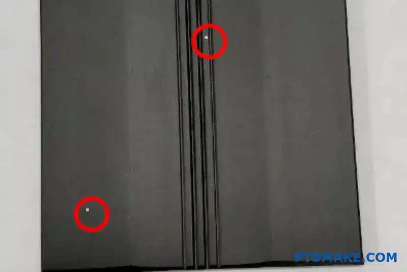
How can you visually inspect a part for seal quality?
The Dye Spot Test: A Simple Visual Check
One of the most reliable visual methods is the dye spot test. It’s a straightforward way to confirm the quality of a seal, especially after finishing processes like anodizing.
The principle is simple. A special dye is applied to the surface. If the seal is poor, the dye will seep into any open pores. A good seal prevents this.
This test quickly reveals sealing defects that are invisible to the naked eye. It provides clear, actionable results for quality control.
| Test Result | Interpretation | Action Required |
|---|---|---|
| No Stain | Pores are properly sealed. | Part passes inspection. |
| Light Stain | Minor sealing issues. | Review process parameters. |
| Heavy Stain | Significant sealing failure. | Part fails, requires rework. |
The Procedure in Detail
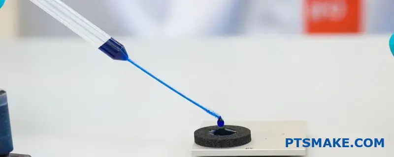
A Deeper Look at the Dye Spot Test
The dye spot test, often guided by standards like ISO 2143, is a critical step in our quality assurance process at PTSMAKE. It’s a destructive test, meaning it’s typically performed on sample parts from a batch to validate the entire sealing process. The test confirms that the microscopic structure of the surface is properly closed off.
Step-by-Step Execution
First, the part surface must be clean and dry. Any contaminants could give a false result. We then apply a specific testing dye to a small area. The dye is formulated to penetrate any unsealed openings.
After a set dwell time, usually a few minutes, we wipe the excess dye off completely. The key is what remains. A perfectly sealed surface will show no trace of color. Any remaining stain indicates the dye has entered the surface porosity17, signaling an incomplete seal.
Interpreting the Results
The intensity of the stain tells the story. A faint spot might mean the seal is marginal. A dark, clear stain points to a significant failure in the sealing process. In our past projects, we’ve found this test invaluable for optimizing anodizing and other sealing treatments. It provides immediate feedback, allowing us to adjust parameters and ensure every production run meets the required specifications for our clients. It’s a simple test that prevents complex field failures.
A well-executed dye test provides confidence. It ensures the protective layer is continuous and will perform as designed, preventing corrosion and wear over the part’s lifetime.
This simple visual check provides immediate feedback on your sealing process. The dye spot test is an effective method for verifying that surfaces, especially after anodizing, are properly sealed against contaminants and corrosion, ensuring part integrity and performance.
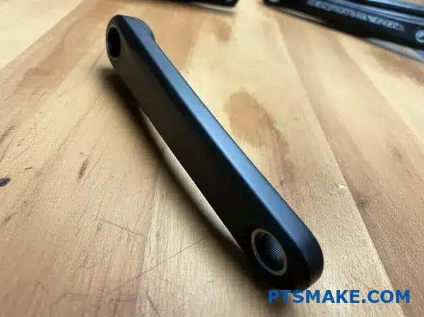
Design the full anodizing spec for a bicycle crank arm.
Creating a precise anodizing specification is crucial for bicycle crank arms. It’s not just about looks; it’s about durability. We begin with the right material, 6061-T6 aluminum, known for its strength and excellent response to anodizing.
For this component, I always specify Type II anodizing. This provides a perfect balance of corrosion resistance, wear protection, and aesthetic quality. A detailed spec removes guesswork and ensures every part meets the design intent.
Here’s a summary of a solid specification:
| Parameter | Specification | Purpose |
|---|---|---|
| Anodizing Type | Type II, Class 2 | Durability & Color |
| Coating Thickness | 8 – 12 µm | Wear Resistance |
| Color | Black (or custom) | Aesthetics |
| Seal Type | Mid-Temperature Seal | Longevity & Fade Resistance |
The Foundation: Choosing 6061-T6 Aluminum
The entire specification starts with the material. 6061-T6 is an excellent choice for crank arms. It offers high strength-to-weight ratio and great machinability. More importantly, its composition makes it ideal for achieving a consistent, high-quality anodized finish. Other alloys might not dye as evenly.
Crafting the Process Specification
A complete spec sheet guides the entire finishing process. This is something we refine constantly with our partners at PTSMAKE to ensure repeatability. The process involves growing a controlled oxide layer through electrolytic passivation18. It’s more than just a coating; it’s an integral part of the surface.
The full process unfolds in distinct stages:
| Process Step | Description | Key Objective |
|---|---|---|
| 1. Pre-treatment | Degreasing and alkaline etching | Create a clean, uniform surface |
| 2. Anodizing | Sulfuric acid bath (Type II) | Grow the anodic layer to 8-12 µm |
| 3. Coloring | Immersion in organic dye | Achieve the specified color (e.g., black) |
| 4. Sealing | Mid-temperature sealing process | Close the pores of the oxide layer |
The 8-12 µm thickness is the sweet spot. It’s thick enough to resist scratches and wear from shoes but not so thick that it compromises the part’s fatigue life, a critical factor for a crank arm.
Key Quality Control Checks
Finally, the spec must include quality control checkpoints. These are non-negotiable. We verify coating thickness with eddy current testing. We also perform visual inspections for color consistency and a cross-hatch adhesion test to ensure the coating won’t flake.
A detailed specification is the blueprint for a perfect finish. Starting with 6061-T6 aluminum and specifying Type II anodizing with clear thickness, color, and sealing requirements ensures a durable and beautiful crank arm that performs reliably.
How do you balance cost versus performance in process selection?
Choosing the right finish is critical. A client recently needed a durable black finish for an architectural panel. This presented a common dilemma. Should they choose a standard dyed Type II anodize or a more robust Type III hardcoat?
This decision isn’t just about color. It’s a balance of cost, aesthetics, and long-term durability. Each option has clear trade-offs.
Comparing Anodizing Options
We weighed the initial investment against the product’s entire lifecycle. The environment where the panel will be used is a key factor.
Here is a quick overview of the initial considerations:
| Finish Type | Upfront Cost | Key Benefit |
|---|---|---|
| Dyed Type II | Lower | Good aesthetics, moderate protection |
| Type III Hardcoat | Higher | Superior abrasion resistance |
A Deeper Look at the Trade-Offs
When we move past the initial quote, the true cost becomes clearer. The performance over time is where the real value lies.
Upfront Cost and Energy
Type III hardcoat anodizing is more expensive for a reason. The process requires lower temperatures and significantly more electrical energy. This drives up the initial production cost compared to Type II.
For budget-sensitive projects, this can be a major hurdle. However, looking only at this figure can be misleading for long-term applications.
Durability and Long-Term Performance
This is where the two processes really diverge. Anodizing is an electrolytic passivation process19 that creates a protective oxide layer. The type of process determines how protective that layer is.
For an architectural panel exposed to the elements, durability is paramount.
Abrasion Resistance: Type III creates a much harder, denser layer. It’s far more resistant to scratches and wear than Type II. This is crucial for high-traffic areas.
UV Stability: Organic dyes used in Type II can fade over time with sun exposure. A dyed Type III finish generally offers better color retention, preserving the intended look for much longer.
The table below breaks down their performance characteristics:
| Feature | Dyed Type II | Type III Hardcoat |
|---|---|---|
| Abrasion Resistance | Good | Excellent |
| UV Stability (Dyed) | Fair to Good | Good to Excellent |
| Long-Term Value | Lower | Higher |
For architectural panels, Type III hardcoat’s superior durability and UV resistance often justify the higher initial cost. This ensures the part maintains its function and appearance for years, avoiding costly replacements or refinishing.
Your line’s black dye tank yields inconsistent shades. How do you fix it?
Random adjustments won’t fix inconsistent black dye shades. You need a structured approach. Guesswork leads to more scrap and wasted time. It’s time to stop guessing and start solving the problem methodically.
For this, we use a framework like Six Sigma’s DMAIC. This system provides a clear, data-driven roadmap. It guides you from problem definition to a permanent solution. It is a powerful tool for process control.
The DMAIC Framework
| Phase | Objective |
|---|---|
| Define | Clearly state the problem and goals. |
| Measure | Collect data on the current process. |
| Analyze | Identify the root cause of the problem. |
| Improve | Implement a solution to fix the root cause. |
| Control | Sustain the improvements over time. |
Define and Measure the Problem
First, you must define "inconsistent shade" with numbers. Subjective terms like "too light" or "too dark" are useless. Use a spectrocolorimeter to measure the Lab color space values of your parts. This gives you a baseline. Your goal is a specific Lab value with a tight tolerance.
Next, you measure everything. Document every variable in your anodizing dye process for a batch of parts. This includes dye concentration, pH, tank temperature, immersion time, and current density. Don’t leave anything out. Create a detailed log for every run, whether it’s good or bad.
Analyze and Improve
With data in hand, you can analyze. Look for correlations. Does the shade value shift when the pH drifts by 0.2? Does a 2°C temperature change affect the outcome? This analysis phase points you to the true root cause, not just a symptom.
Once you identify the cause, you can improve the process. If pH is the culprit, install an automated dosing system. If temperature is unstable, upgrade your heating and cooling controls. These improvements should be targeted directly at the root causes found during your analysis.
Control for Long-Term Consistency
Finally, you implement controls to maintain the gains. This is the most critical step. Create clear Standard Operating Procedures (SOPs) for your team. Use statistical process control charts to monitor key variables in real-time. This helps maintain a high Process Capability Index (Cpk)20, ensuring the process stays within its new, tighter limits. At PTSMAKE, we find that robust control systems are the key to repeatable quality.
| Parameter | Recommended Control Method |
|---|---|
| Dye Concentration | Regular Titration & Dosing |
| pH Level | Automated Sensor and Dosing System |
| Tank Temperature | Thermostatic Heaters & Chillers |
| Immersion Time | Timed, Automated Hoist System |
The DMAIC framework provides a disciplined, data-driven path. It moves you from identifying shade inconsistency to implementing robust controls. This ensures your anodizing process delivers predictable, high-quality results every time, eliminating guesswork and rework.
How would you adapt a process for RoHS and REACH compliance?
Transitioning away from a chromate-based seal is a common challenge due to RoHS. Imagine your anodizing line uses one. You must shift to a compliant, non-chromate alternative. This isn’t just a simple swap. It’s a full process adaptation.
This change requires careful planning and validation. You need to ensure the new seal performs just as well, if not better. It impacts everything from equipment to quality control.
Initial Transition Steps
Here is a quick look at the first steps we take at PTSMAKE when facing this challenge.
| Step | Action | Key Consideration |
|---|---|---|
| 1 | Research Alternatives | Evaluate non-chromate seals (e.g., trivalent chromium, permanganate). |
| 2 | Supplier Consultation | Work with chemical suppliers to understand bath requirements. |
| 3 | Small-Scale Testing | Run trials on sample parts to test performance. |
This initial phase sets the stage for a smooth, full-scale changeover.
Detailing the Changeover Plan
A successful transition requires a detailed, step-by-step plan. We don’t just dump the old chemicals and pour in the new ones. It’s a meticulous process to avoid contamination and ensure performance.
Bath Changeover Procedure
First, you must safely drain and dispose of the old hexavalent chromium solution. This must follow strict environmental regulations. The tank is then thoroughly cleaned and rinsed. Any remaining residue can ruin the new bath.
Next, you introduce the new non-chromate sealing solution. You must follow the supplier’s instructions precisely for concentration, pH, and temperature. These parameters are critical for proper passivation21 of the part’s surface.
Process Re-validation
Once the new bath is ready, you can’t assume it works the same way. Re-validation is essential. This means running controlled tests to define the new operating window. We document everything, from immersion times to temperature ranges.
Performance Testing Protocol
The final and most crucial step is performance testing. The new seal must meet or exceed the old one’s capabilities. We conduct a series of rigorous tests to confirm this.
| Test Type | Purpose | Acceptance Criteria |
|---|---|---|
| Corrosion Resistance | Verify protection against environmental factors. | Pass salt spray test (e.g., ASTM B117) for a specified duration. |
| Adhesion Testing | Ensure paint or coating will stick properly. | No peeling or flaking after cross-hatch test (e.g., ASTM D3359). |
| Appearance | Check for cosmetic consistency. | Matches color and finish of approved standard samples. |
This detailed testing ensures the final product is fully compliant and meets all customer specifications.
Transitioning from chromate seals is a necessary step for RoHS compliance. The process involves selecting a new seal, executing a careful bath changeover, and conducting rigorous process re-validation and performance testing to ensure quality is never compromised.
How can anodizing create novel functional surfaces?
Anodizing offers much more than just corrosion and wear resistance. By innovating the process, we can engineer surfaces with remarkable functionalities. It’s about moving beyond standard protocols.
At PTSMAKE, we explore how small changes can yield big results. This opens doors to creating truly "smart" materials for our clients.
Pushing the Boundaries of Anodizing
The key lies in precisely modifying the anodizing parameters. We can manipulate the electrical current or alter the chemical bath. This level of control is what unlocks novel surface properties. It’s a fascinating area of material science.
Process Modifications
Simple adjustments can lead to complex surface structures. For instance, instead of a steady current, we can use a pulsed one. This changes how the oxide layer grows on a nano-scale, creating unique topographies.
| Feature | Standard Anodizing | Modified Anodizing |
|---|---|---|
| Goal | Corrosion/Wear Resistance | Specific Functionality |
| Process | Constant Current | Pulsed Current, Varied Electrolytes |
| Outcome | Uniform Oxide Layer | Tailored Pore Structure/Chemistry |
Crafting Functional Surfaces: The "How"
Creating these novel surfaces requires deep process knowledge. It’s not just about following a spec sheet; it’s about understanding the underlying electrochemical reactions and how to influence them for a desired outcome.
Pulse Anodizing for Structural Control
Instead of applying a constant DC current, pulse anodizing uses alternating high and low currents. This technique gives us exceptional control over the nanopore dimensions—their diameter, depth, and spacing. By tuning these pulses, we can build a highly ordered and specific nanostructure directly into the surface. In our tests, this precision is what enables advanced functionalities.
The Role of Electrolytes
The choice of electrolyte is equally critical. While sulfuric acid is common, using alternatives like phosphoric, oxalic, or other organic acids changes the game. Each electrolyte interacts with the aluminum differently, altering the chemical composition and geometry of the oxide layer. This allows us to engineer a surface’s energy, which dictates how it interacts with liquids. This is how we can achieve properties like superhydrophobicity22, where water droplets bead up and roll right off, taking dirt with them. We can also create highly porous surfaces with a massive surface area, ideal for catalytic applications.
A Practical Application Example
Imagine a medical device component that actively repels blood and bacteria. Or consider a heat sink that is both electrically insulating and superhydrophobic, preventing short circuits from condensation. These are not futuristic concepts; they are achievable today through modified anodizing.
| Modification | Resulting Property | Potential Application |
|---|---|---|
| Pulse Anodizing | Highly ordered nanopores | Enhanced Catalysis in Reactors |
| Organic Electrolyte | Low Surface Energy | Self-Cleaning Electronic Enclosures |
| Mixed Acid Bath | Unique pore morphology | Advanced Filtration Membranes |
By manipulating anodizing parameters like current and electrolytes, we move beyond basic protection. We can create surfaces with unique properties like superhydrophobicity or enhanced catalytic activity, unlocking innovative applications across many industries.
How would you advise a design engineer about their part?
An engineer recently presented a complex machined part. It featured deep pockets and several welded elements. Their goal was a flawless anodizing finish.
However, the design itself presented several challenges. The best advice focuses on making small, strategic design changes before manufacturing begins.
These adjustments are crucial for a successful outcome. They ensure the anodizing process is smooth and the final part is both durable and visually appealing.
| Design Feature | Potential Anodizing Issue |
|---|---|
| Sharp Corners | Weak, thin coating and potential cracks |
| Deep Pockets | Trapped chemicals leading to stains |
| Welded Areas | Uneven finish and corrosion risk |
Rethinking the Design for a Better Finish
Achieving a perfect anodized finish isn’t just about the chemical process. It starts with the part’s geometry and material choices. In past projects at PTSMAKE, we’ve found that early collaboration with design engineers prevents costly rework and ensures superior results.
The Problem with Sharp Corners
Sharp internal and external corners are a major issue for anodizing. The electrical current used in the process concentrates on these edges. This results in a thin, brittle oxide layer that can easily chip or crack. By simply adding a small radius, you allow for a much more uniform and durable coating.
Material Compatibility is Key
Anodizing is an electrochemical process designed specifically for aluminum alloys. When you introduce welded elements made of a different material, you create a major problem.
The process will fail at the weld, and it can also introduce galvanic corrosion23 where the two metals meet. The best practice is to weld with a compatible aluminum filler rod or, even better, design the component as a single machined part to eliminate welding entirely.
Allowing for Proper Drainage
Deep pockets or blind holes can trap the acids and rinsing solutions used during anodizing. If these chemicals aren’t completely removed, they will cause stains, streaks, and long-term corrosion.
| Design Flaw | Simple Design Fix |
|---|---|
| Sharp internal/external corners | Add a minimum 0.5mm radius |
| Sealed pockets or channels | Design small, discreet drainage holes |
| Dissimilar metal welds | Redesign as a single part or use compatible filler |
A small, strategically placed drainage hole is often all that’s needed to solve this. It ensures all liquids can flow in and out freely, guaranteeing a clean and consistent finish across the entire part.
Simple design changes like rounding corners, avoiding dissimilar metals, and adding drainage holes are critical for successful anodizing. These small steps prevent major defects, ensuring a durable, high-quality finish for your machined aluminum parts.
How can you mask a part for selective anodizing?
Selective anodizing is a crucial process. You need it when certain areas of a part must remain conductive for electrical grounding. Or perhaps an area needs to be bare for later welding or bonding. The key is masking.
This technique protects specific surfaces from the anodizing bath. The right masking method ensures only the desired areas receive the protective oxide layer. It’s a game of precision.
We use several masking methods at PTSMAKE. The choice depends on the part’s geometry, required precision, and production volume. Let’s look at the main options.
| Masking Method | Best For | Precision |
|---|---|---|
| Tapes | Flat surfaces | Low-Medium |
| Lacquers | Complex geometries | High |
| Plugs | Holes, Threads | High |

Masking Tapes
Tapes are a common starting point for selective anodizing. Polyester or vinyl tapes are popular because they can withstand the chemicals in the anodizing tank. The process is straightforward: apply the tape firmly to the area you want to protect.
However, tapes have limits. They are best for flat or simple curved surfaces. On complex parts, the tape can lift at the edges. This allows acid to seep underneath, creating a blurry or "leaked" anodizing line. Precision can be a challenge. While cheap and easy to apply for simple jobs, removal can sometimes leave adhesive residue.
Masking Lacquers and Paints
When precision is critical, we often turn to masking lacquers. These are liquid masks that are painted or sprayed onto the surface. Once applied, they need time to cure, forming a durable, chemical-resistant barrier.
Lacquers conform perfectly to any shape. This makes them ideal for intricate geometries where tape would fail. They create very sharp, clean lines. The main drawback is the labor involved. Application and removal are more time-consuming than tape. This adds to the overall cost, especially for low-volume runs. The material must also have sufficient dielectric strength24 to prevent current flow through the masked area.
Custom Plugs and Caps
For parts with holes, threads, or specific cavities, plugs are the best solution. Made from materials like silicone or rubber, these plugs create a perfect seal. They prevent any part of the hole or thread from being anodized.
This method is highly repeatable and fast, making it excellent for high-volume production. The plugs are reusable, which helps offset the initial cost of creating custom molds. The main downside is that initial tooling for custom plugs can be an investment. It’s not always cost-effective for one-off prototypes.
Choosing the right masking method is a balance of precision, part complexity, and cost. Each technique has its place. Your project requirements will determine whether tape, lacquer, or plugs are the most effective solution for your selective anodizing needs.
Develop your personal troubleshooting philosophy for anodizing defects.
When an anodizing defect appears, chaos is the enemy. A scattered approach wastes time and resources. You need a personal philosophy, a mental model that guides your every step. This isn’t about memorizing charts; it’s about building a logical investigation sequence.
A systematic approach ensures you don’t miss clues. It moves from the most likely and easiest-to-check causes to the more complex ones. This saves valuable production time. Below is a comparison of two common approaches we’ve observed in the industry.
| Chaotic Approach | Systematic Approach |
|---|---|
| Guess based on instinct | Follow a logical sequence |
| Check complex variables first | Start with the simplest checks |
| Blame the anodizing tank | Examine evidence on the part |
| Often leads to repeat errors | Leads to a permanent solution |
Developing your own system is key to consistent quality.
My Go-To Investigation Sequence
Over the years, I’ve refined a troubleshooting sequence that starts at the end and works backward. This method quickly isolates the root cause by eliminating variables in a logical order. My philosophy is simple: start with the physical evidence and move toward the chemical processes.
Step 1: Examine the Part and the Defect
First, I always look at the part itself. Where is the defect located? Is it uniform across the surface or localized? Is it on every part or just some? The defect’s appearance—be it pitting, burning, or color inconsistency—is the primary clue. It tells you where to look next. A defect near a contact point suggests a racking issue, not a chemical imbalance.
Step 2: Inspect the Racking
If the part points to a contact issue, the racking is the next logical step. Racking is a frequent source of anodizing defects. I check for secure electrical contact. Are the clamps tight? Is there any sign of arcing or burning? Sometimes, using dissimilar metals can cause issues like galvanic corrosion25, disrupting the current flow and ruining the finish. A loose rack is a much easier fix than adjusting an entire tank’s chemistry.
Step 3: Review Pre-Treatment Processes
If racking is fine, I move to pre-treatment. A flawless anodized layer cannot form on a poorly prepared surface. I ask: Was the part properly cleaned? Was the etch or de-smut stage timed correctly? Residual oils or improper rinsing will cause major problems. These steps are foundational.
Step 4: Analyze the Anodizing Tank
Only after ruling out the previous steps do I investigate the anodizing tank itself. This is my last resort. Checking bath chemistry, temperature, and power supply parameters is more complex. You don’t want to adjust a perfectly good tank if the problem was simply a dirty part.
This backward approach, from part to tank, is the most efficient troubleshooting model I’ve used.
My personal philosophy is to work backward from the final product. This sequence, from part to racking, pre-treatment, and finally the tank, saves time by addressing the most common and easily-fixed issues first, ensuring a logical and efficient problem-solving process.
Unleash Anodizing Excellence: Partner with PTSMAKE Today
Looking for flawless anodizing on your precision aluminum or metal parts? PTSMAKE delivers superior quality, consistent results, and on-time production for global OEMs. Experience manufacturing peace of mind—send us your RFQ now for expert consultation and a fast quote!

Learn how the choice of electrolyte impacts the final color, hardness, and porosity of the finish. ↩
Learn how these microscopic particles affect the quality and uniformity of your anodized finish. ↩
Learn how this property is measured and why it’s vital for your electronic components. ↩
Learn how part geometry can create electrical shields, blocking the coating process in certain areas. ↩
Learn why the base material is critical for surface treatment success and how it interacts with coatings. ↩
Learn how this process gathers tiny particles into larger clumps for efficient water purification. ↩
Learn how the oxide layer’s internal structure impacts its final performance and durability. ↩
Understand how surface treatments affect the lifespan and durability of critical metal components. ↩
Learn how lightfastness ratings impact the long-term appearance and durability of your colored parts. ↩
Learn how different anodizing types protect aluminum parts from environmental degradation and extend their service life. ↩
Discover how current density is critical for achieving a flawless and uniform anodized finish. ↩
Discover how this electrical efficiency concept directly affects the quality and cost-effectiveness of your anodized parts. ↩
Discover how this process transforms the metal’s surface itself, rather than just adding a layer on top. ↩
Understand how an alloy’s internal structure affects the final quality and performance of an anodized finish. ↩
Discover how managing current density ensures a uniform and durable anodized finish. ↩
Learn how this instrument measures color precisely, ensuring your parts meet exact specifications every single time. ↩
Understand how surface porosity affects sealing and part longevity. ↩
Learn how this electrochemical process transforms the aluminum surface into a hard, protective oxide layer. ↩
Discover the science behind this process and how it creates a durable, corrosion-resistant surface. ↩
Discover how this metric quantifies your process’s ability to consistently meet quality specifications. ↩
Learn how this chemical process enhances corrosion resistance on metal surfaces. ↩
Discover the science behind these water-repelling surfaces and their exciting engineering applications. ↩
Discover how this electrochemical process can cause premature part failure when different metals are in contact. ↩
Learn how this electrical property is critical for effective masking in anodizing processes. ↩
Understand how dissimilar metals can create electrical issues that compromise your anodizing results. ↩